

Page 1
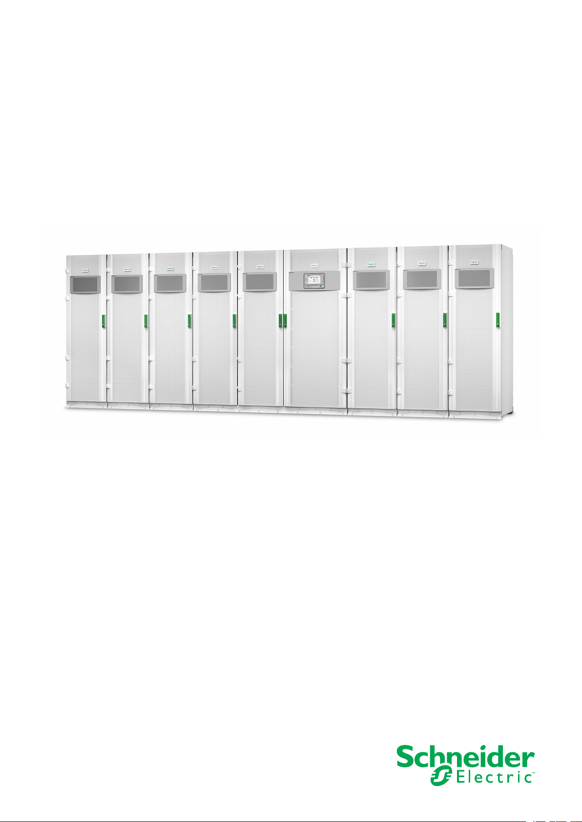
Galaxy VX
380 V, 400 V, 415 V, and 440 V UPS System
Technical Specifications
07/2020
www.schneider-electric.com
Page 2

Legal Information
The Schneider Electric brand and any trademarks of Schneider Electric SE and its
subsidiaries referred to in this guide are the property of Schneider Electric SE or its
subsidiaries. All other brands may be trademarks of their respective owners.
This guide and its content are protected under applicable copyright laws and
furnished for informational use only. No part of this guide may be reproduced or
transmitted in any form or by any means (electronic, mechanical, photocopying,
recording, or otherwise), for any purpose, without the prior written permission of
Schneider Electric.
Schneider Electric does not grant any right or license for commercial use of the guide
or its content, except for a non-exclusive and personal license to consult it on an "as
is" basis. Schneider Electric products and equipment should be installed, operated,
serviced, and maintained only by qualified personnel.
As standards, specifications, and designs change from time to time, information
contained in this guide may be subject to change without notice.
To the extent permitted by applicable law, no responsibility or liability is assumed by
Schneider Electric and its subsidiaries for any errors or omissions in the informational
content of this material or consequences arising out of or resulting from the use of the
information contained herein.
Go to: https://www.productinfo.schneider-electric.com/galaxyvx_iec/
or scan the QR code above for digital experience and translated manuals.
Page 3

Table of Contents
Important Safety Instructions — SAVE THESE
380 V, 400 V, 415 V, and 440 V UPS System
INSTRUCTIONS
Electromagnetic Compatibility .....................................................................6
Safety Precautions .....................................................................................6
.........................................................................................5
Technical Data.............................................................................................8
System Overview .......................................................................................8
Model List ..................................................................................................9
Overview of Configurations .......................................................................10
Overview of UPSs with 1250 kW I/O Cabinet - Single Utility/
Mains................................................................................................. 10
Overview of UPSs with 1250 kW I/O Cabinet - Dual Utility/Mains ............ 11
Overview of UPSs with 1500 kW I/O Cabinet – Single Utility/
Mains................................................................................................. 11
Overview of UPSs with 1500 kW I/O Cabinet – Dual Utility/Mains ...........12
Input Power Factor ...................................................................................12
Input Voltage Window ...............................................................................13
Inverter Short-Circuit Capabilities (Bypass not Available)............................. 15
Efficiency for UPSs with 1250 kW I/O Cabinet.............................................16
Efficiency for UPSs with 1500 kW I/O Cabinet.............................................18
Derating Due to Load Power Factor ........................................................... 20
Batteries .................................................................................................. 21
Battery Runtimes for Li-Ion Battery Cabinets LIBATTSMGGIEC .............21
End of Discharge Voltage .................................................................... 23
Battery Voltage Range ........................................................................ 23
Compliance.............................................................................................. 24
Communication and Management .............................................................24
EPO Connections ............................................................................... 24
Overview of Input Contacts and Output Relays...................................... 25
Facility Planning ........................................................................................ 27
Specifications for 500 kW UPS ..................................................................27
Specifications for 625 kW UPS ..................................................................29
Specifications for 750 kW UPS ..................................................................31
Specifications for 800 kW UPS ..................................................................33
Specifications for 1000 kW UPS ................................................................ 35
Specifications for 1100 kW UPS................................................................. 37
Specifications for 1250 kW UPS ................................................................ 39
Specifications for 1500 kW UPS ................................................................ 41
Recommended Upstream Protection and Cable Sizes – IEC........................42
Weights and Dimensions........................................................................... 45
Weights and Dimensions for UPSs with 1250 kW I/O Cabinet................. 45
Weights and Dimensions for UPSs with 1500 kW I/O Cabinet................. 46
Clearance ................................................................................................ 46
Clearance for UPSs with 1250 kW I/O Cabinet ...................................... 46
Clearance for UPSs with 1500 kW I/O Cabinet ...................................... 46
Guidance for Organizing Battery Cables.....................................................47
Torque Specifications................................................................................47
Environment............................................................................................. 48
990-5850F-001 3
Page 4

380 V, 400 V, 415 V, and 440 V UPS System
Heat Dissipation (BTU/hr) for UPSs with 1250 kW I/O Cabinet ..................... 48
Heat Dissipation (BTU/hr) for UPSs with 1500 kW I/O Cabinet ..................... 51
Options .......................................................................................................53
Hardware Options.....................................................................................53
Configuration Options ............................................................................... 53
Limited Factory Warranty......................................................................... 54
4 990-5850F-001
Page 5
Important Safety Instructions — SAVE THESE
INSTRUCTIONS 380 V, 400 V, 415 V, and 440 V UPS System
Important Safety Instructions — SAVE THESE INSTRUCTIONS
Read these instructions carefully and look at the equipment to become familiar
with it before trying to install, operate, service or maintain it. The following safety
messages may appear throughout this manual or on the equipment to warn of
potential hazards or to call attention to information that clarifies or simplifies a
procedure.
The addition of this symbol to a “Danger” or “Warning” safety
message indicates that an electrical hazard exists which will result in
personal injury if the instructions are not followed.
This is the safety alert symbol. It is used to alert you to potential
personal injury hazards. Obey all safety messages with this symbol
to avoid possible injury or death.
DANGER
DANGER indicates a hazardous situation which, if not avoided, will result in
death or serious injury.
Failure to follow these instructions will result in death or serious injury.
WARNING
WARNING indicates a hazardous situation which, if not avoided, could result
in death or serious injury.
Failure to follow these instructions can result in death, serious injury, or
equipment damage.
CAUTION
CAUTION indicates a hazardous situation which, if not avoided, could result in
minor or moderate injury.
Failure to follow these instructions can result in injury or equipment
damage.
NOTICE
NOTICE is used to address practices not related to physical injury. The safety
alert symbol shall not be used with this type of safety message.
Failure to follow these instructions can result in equipment damage.
Please Note
Electrical equipment should only be installed, operated, serviced, and maintained
by qualified personnel. No responsibility is assumed by Schneider Electric for any
consequences arising out of the use of this material.
A qualified person is one who has skills and knowledge related to the construction,
installation, and operation of electrical equipment and has received safety training
to recognize and avoid the hazards involved.
990-5850F-001 5
Page 6
380 V, 400 V, 415 V, and 440 V UPS System
Electromagnetic Compatibility
RISK OF ELECTROMAGNETIC DISTURBANCE
This is a product Category C3 according to IEC 62040-2. This is a product for
commercial and industrial applications in the second environment - installation
restrictions or additional measures may be needed to prevent disturbances. The
second environment includes all commercial, light industry, and industrial
locations other than residential, commercial, and light industrial premises
directly connected without intermediate transformer to a public low-voltage
mains supply. The installation and cabling must follow the electromagnetic
compatibility rules, e.g.:
• the segregation of cables,
• the use of shielded or special cables when relevant,
• the use of grounded metallic cable tray and supports.
Failure to follow these instructions can result in equipment damage.
Important Safety Instructions — SAVE THESE
INSTRUCTIONS
NOTICE
Safety Precautions
DANGER
HAZARD OF ELECTRIC SHOCK, EXPLOSION, OR ARC FLASH
• The product must be installed according to the specifications and
requirements as defined by Schneider Electric. It concerns in particular the
external and internal protections (upstream circuit breakers, battery circuit
breakers, cabling, etc.) and environmental requirements. No responsibility is
assumed by Schneider Electric if these requirements are not respected.
• After the UPS system has been electrically wired, do not start up the system.
Start-up must only be performed by Schneider Electric.
Failure to follow these instructions will result in death or serious injury.
DANGER
HAZARD OF ELECTRIC SHOCK, EXPLOSION, OR ARC FLASH
The UPS System must be installed according to local and national regulations.
Install the UPS according to:
• IEC 60364 (including 60364–4–41- protection against electric shock, 60364–
4–42 - protection against thermal effect, and 60364–4–43 - protection
against overcurrent), or
• NEC NFPA 70
depending on which one of the standards apply in your local area.
Failure to follow these instructions will result in death or serious injury.
DANGER
HAZARD OF ELECTRIC SHOCK, EXPLOSION, OR ARC FLASH
• Install the UPS system in a temperature controlled area free of conductive
contaminants and humidity.
• Install the UPS system on a non-inflammable, level, and solid surface (e.g.
concrete) that can support the weight of the system.
Failure to follow these instructions will result in death or serious injury.
6 990-5850F-001
Page 7
Important Safety Instructions — SAVE THESE
INSTRUCTIONS 380 V, 400 V, 415 V, and 440 V UPS System
DANGER
HAZARD OF ELECTRIC SHOCK, EXPLOSION, OR ARC FLASH
The UPS is not designed for and must therefore not be installed in the following
unusual operating environments:
• Damaging fumes
• Explosive mixtures of dust or gases, corrosive gases, or conductive or
radiant heat from other sources
• Moisture, abrasive dust, steam or in an excessively damp environment
• Fungus, insects, vermin
• Salt-laden air or contaminated cooling refrigerant
• Pollution degree higher than 2 according to IEC 60664-1
• Exposure to abnormal vibrations, shocks, and tilting
• Exposure to direct sunlight, heat sources, or strong electromagnetic fields
Failure to follow these instructions will result in death or serious injury.
NOTICE
RISK OF OVERHEATING
Respect the clearance requirements around the UPS system and do not cover
the product’s ventilation openings when the UPS system is in operation.
Failure to follow these instructions can result in equipment damage.
NOTICE
RISK OF EQUIPMENT DAMAGE
Do not connect the UPS output to regenerative load systems including
photovoltaic systems and speed drives.
Failure to follow these instructions can result in equipment damage.
990-5850F-001 7
Page 8
380 V, 400 V, 415 V, and 440 V UPS System Technical Data
Technical Data
System Overview
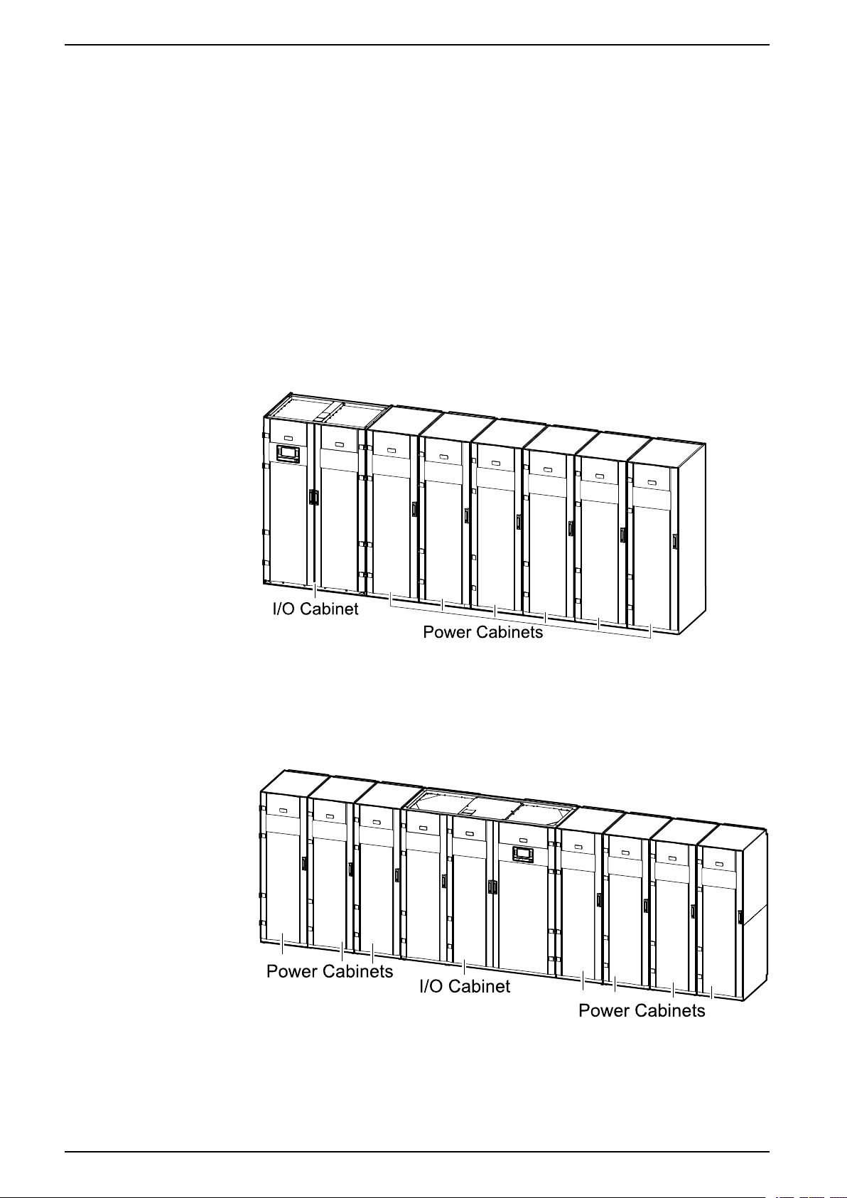
Each Galaxy VX UPS consists of the following components:
• An I/O cabinet for wield wiring containing the static switch, a backfeed
protection switch, and the user interface.
• A number of 250 kW power cabinets containing the power electronics.
UPSs with 1250 kW I/O Cabinet
The 1250 kW I/O cabinet is used for UPS systems from a minimum configuration
of 500 kW with two power cabinets to a maximum configuration of 1250 kW N+1
with six power cabinets. The I/O cabinet is placed to the left and two to six power
cabinets (depending on system size) are placed to the right. The image below
shows the maximum configuration.
UPSs with 1500 kW I/O Cabinet
The 1500 kW I/O cabinet is used for UPS systems from a minimum configuration
of 500 kW with two power cabinets to a maximum configuration of 1500 kW N+1
with seven power cabinets. The image below shows the maximum configuration.
8 990-5850F-001
Page 9

Technical Data 380 V, 400 V, 415 V, and 440 V UPS System
Model List
UPSs with 1250 kW I/O Cabinet
• GVX500K500NHS: Galaxy VX 500 kW, 400 V, start-up 5x8
• GVX500K750NHS: Galaxy VX 500 kW scalable to 750 kW 400 V, start-up
5x8
• GVX500K1000NHS: Galaxy VX 500 kW scalable to 1000 kW 400 V, start-up
5x8
• GVX500K1250NHS: Galaxy VX 500 kW scalable to 1250 kW 400 V, start-up
5x8
• GVX625K625NHS: Galaxy VX 625 kW, 400 V, start-up 5x8
• GVX625K1000NHS: Galaxy VX 625 kW scalable to 1000 kW 400 V, start-up
5x8
• GVX750K500NHS: Galaxy VX 500 kW N+1 redundant UPS 400 V, start-up
5x8
• GVX750K750NHS: Galaxy VX 750 kW, 400V, start-up 5x8
• GVX750K1000NHS: Galaxy VX 750 kW scalable to 1000 kW 400 V, start-up
5x8
• GVX750K1250NHS: Galaxy VX 750 kW scalable to 1250 kW 400 V, start-up
5x8
• GVX800K800NHS: Galaxy VX 800 kW, 400 V, start-up 5x8
• GVX1000K750NHS: Galaxy VX 750 kW N+1 redundant UPS 400 V, start-up
5x8
• GVX1000K1000NHS: Galaxy VX 1000 kW, 400 V, start-up 5x8
• GVX1000K1250NHS: Galaxy VX 1000 kW scalable to 1250 kW 400 V, startup 5x8
• GVX1100K1100NHS: Galaxy VX 1100 kW, 400 V, start-up 5x8
• GVX1250K1000NHS: Galaxy VX 1000 kW N+1 Redundant UPS 400 V, Startup 5x8
• GVX1250K1250NHS: Galaxy VX 1250 kW, 400 V, Start-up 5x8
• GVX1500K1100NHS: Galaxy VX 1100 kW N+1 Redundant UPS 400 V, Start
up 5x8
• GVX1500K1250NHS: Galaxy VX 1250 kW N+1 Redundant UPS 400 V, Startup 5x8
UPSs with 1500 kW I/O Cabinet
• GVX500K1500HS: Galaxy VX 500 kW 400 V scalable to 1500 kW, start-up
5x8
• GVX750K1500HS: Galaxy VX 750 kW 400 V scalable to 1500 kW, start-up
5x8
• GVX1000K1500HS: Galaxy VX 1000 kW 400 V scalable to 1500 kW, start-up
5x8
• GVX1250K1500HS: Galaxy VX 1250 kW 400 V scalable to 1500 kW, start-up
5x8
• GVX1500K1500HS: Galaxy VX 1500 kW 400 V, start-up 5x8
• GVX1750K1500HS: Galaxy VX 1500 kW 400 V N+1 redundant UPS, start-up
5x8
990-5850F-001 9
Page 10
380 V, 400 V, 415 V, and 440 V UPS System Technical Data
Overview of Configurations
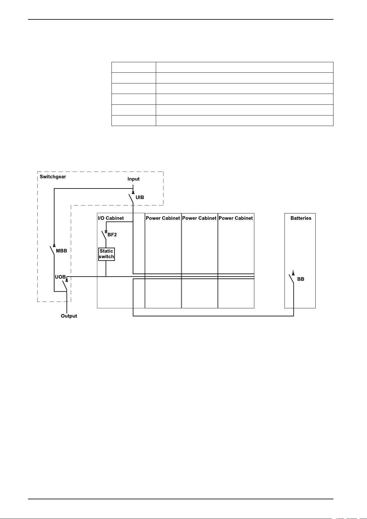
Breakers in the System
UIB Unit input breaker
SSIB Static switch input breaker
BB Battery breaker
MBB Maintenance bypass breaker
UOB Unit output breaker
BF2 Backfeed protection switch
Overview of UPSs with 1250 kW I/O Cabinet - Single Utility/Mains
The illustration shows a 750 kW UPS. The principle is the same for the other
UPSs with the 1250 kW I/O cabinet.
10 990-5850F-001
Page 11
Technical Data 380 V, 400 V, 415 V, and 440 V UPS System
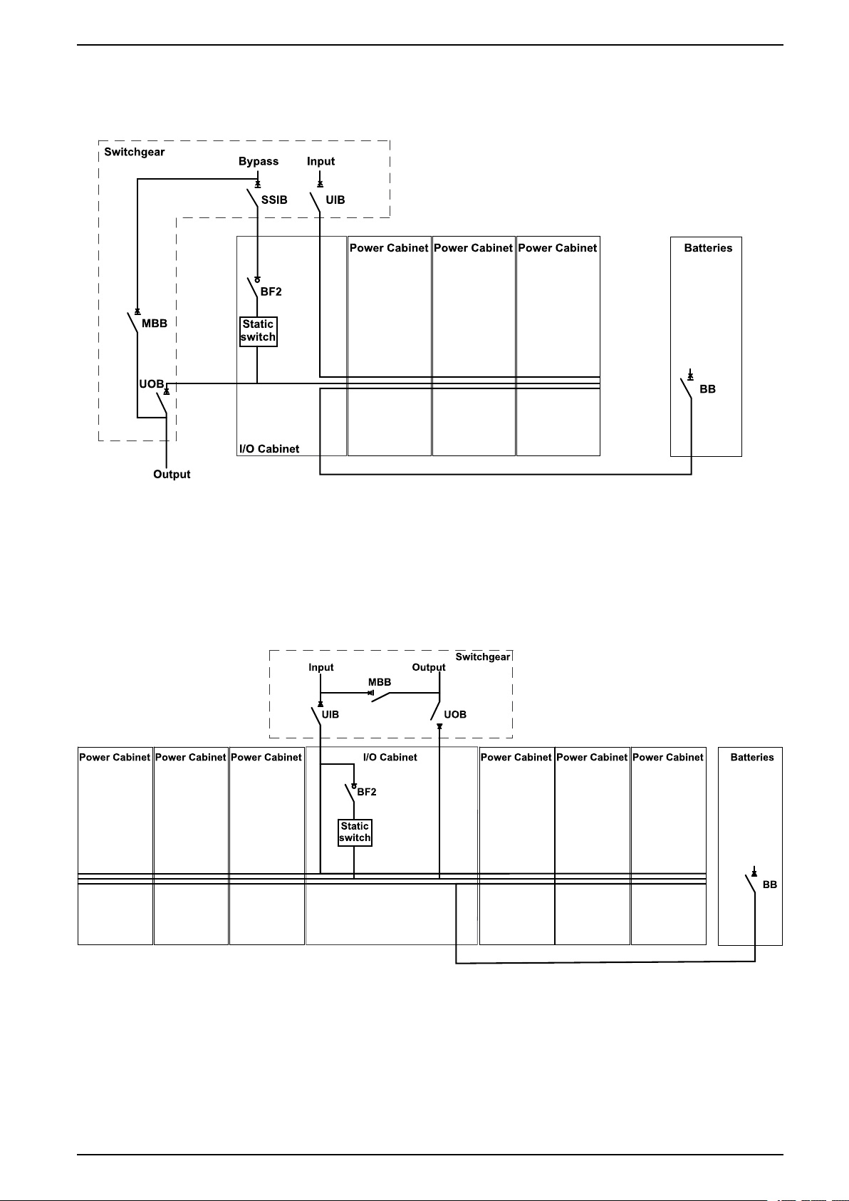
Overview of UPSs with 1250 kW I/O Cabinet - Dual Utility/Mains
The illustration shows a 750 kW UPS. The principle is the same for the other
UPSs with the 1250 kW I/O cabinet.
Overview of UPSs with 1500 kW I/O Cabinet – Single Utility/Mains
The illustration shows a 1500 kW UPS. The principle is the same for the other
UPSs with the 1500 kW I/O cabinet.
Galaxy VX 1500 kW UPS
990-5850F-001 11
Page 12
380 V, 400 V, 415 V, and 440 V UPS System Technical Data
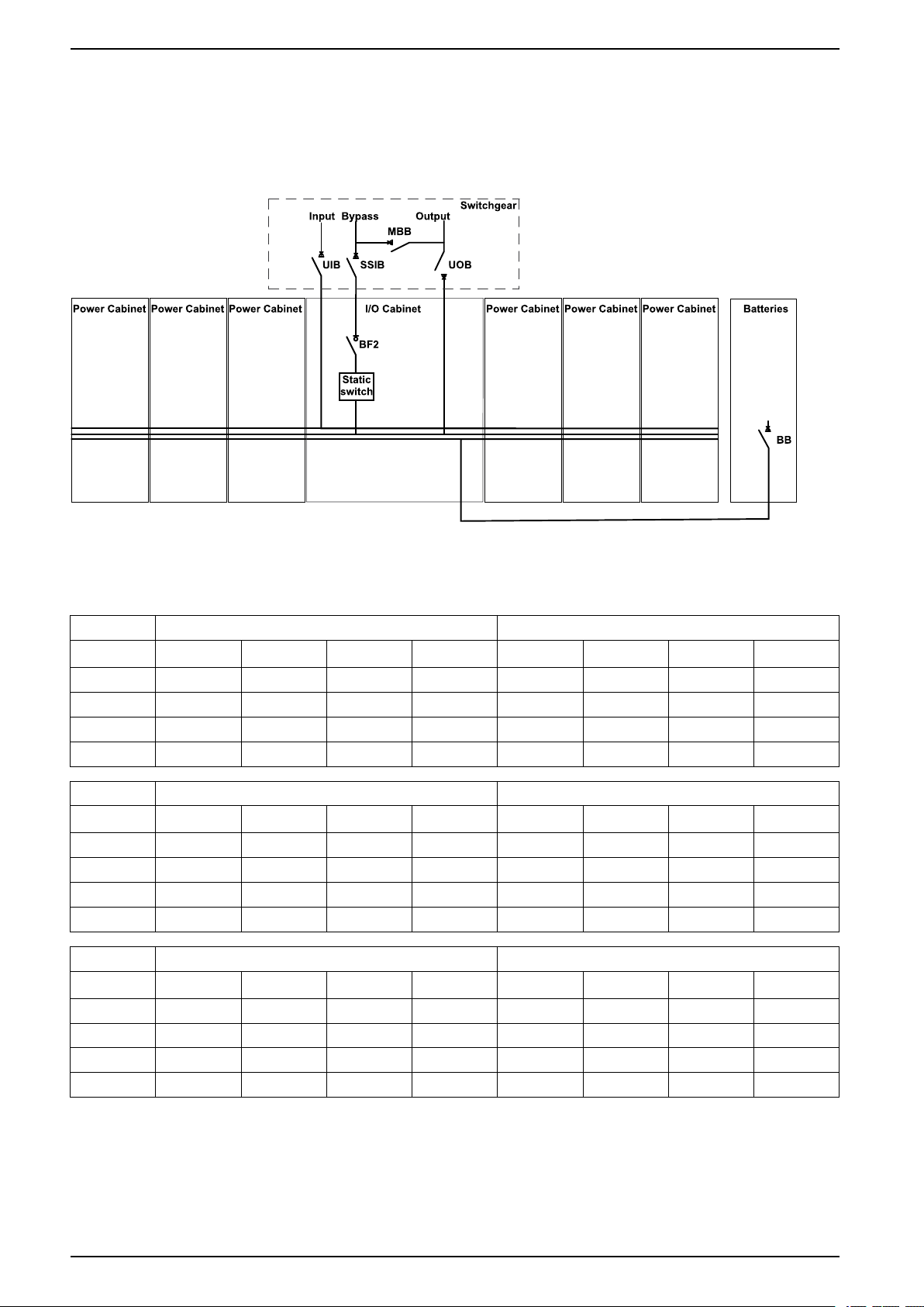
Overview of UPSs with 1500 kW I/O Cabinet – Dual Utility/Mains
The illustration shows a 1500 kW UPS. The principle is the same for the other
UPSs with the 1500 kW I/O cabinet.
Galaxy VX 1500 kW UPS
Input Power Factor
500 kW 625 kW
Voltage (V) 380 400 415 440 V 380 400 415 440 V
25% load 0.98 0.98 0.98 0.98 0.98 0.98 0.98 0.98
50% load 0.99 0.99 0.99 0.99 0.99 0.99 0.99 0.99
75% load 0.99 0.99 0.99 0.99 0.99 0.99 0.99 0.99
100% load 1.00 1.00 1.00 1.00 1.00 1.00 1.00 1.00
750 kW 800 kW
Voltage (V) 380 400 415 440 V 380 400 415 440 V
25% load 0.98 0.98 0.98 0.98 0.98 0.98 0.98 0.98
50% load 0.99 0.99 0.99 0.99 0.99 0.99 0.99 0.99
75% load 0.99 0.99 0.99 0.99 0.99 0.99 0.99 0.99
100% load 1.00 1.00 1.00 1.00 1.00 1.00 1.00 1.00
1000 kW 1100 kW
Voltage (V) 380 400 415 440 V 380 400 415 440 V
25% load 0.98 0.98 0.98 0.98 0.98 0.98 0.98 0.98
50% load 0.99 0.99 0.99 0.99 0.99 0.99 0.99 0.99
75% load 0.99 0.99 0.99 0.99 0.99 0.99 0.99 0.99
100% load 1.00 1.00 1.00 1.00 1.00 1.00 1.00 1.00
12 990-5850F-001
Page 13
Technical Data 380 V, 400 V, 415 V, and 440 V UPS System
1250 kW 1500 kW
Voltage (V) 380 400 415 440 V 380 400 415 440 V
25% load 0.98 0.98 0.98 0.98 0.98 0.98 0.98 0.98
50% load 0.99 0.99 0.99 0.99 0.99 0.99 0.99 0.99
75% load 0.99 0.99 0.99 0.99 0.99 0.99 0.99 0.99
100% load 1.00 1.00 1.00 1.00 1.00 1.00 1.00 1.00
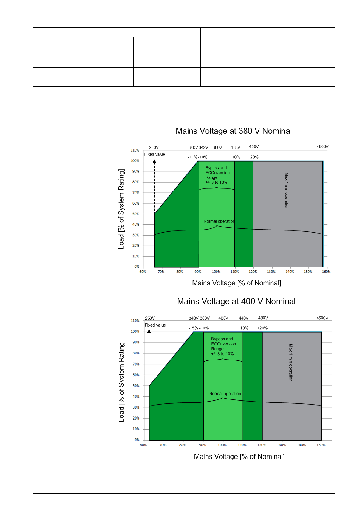
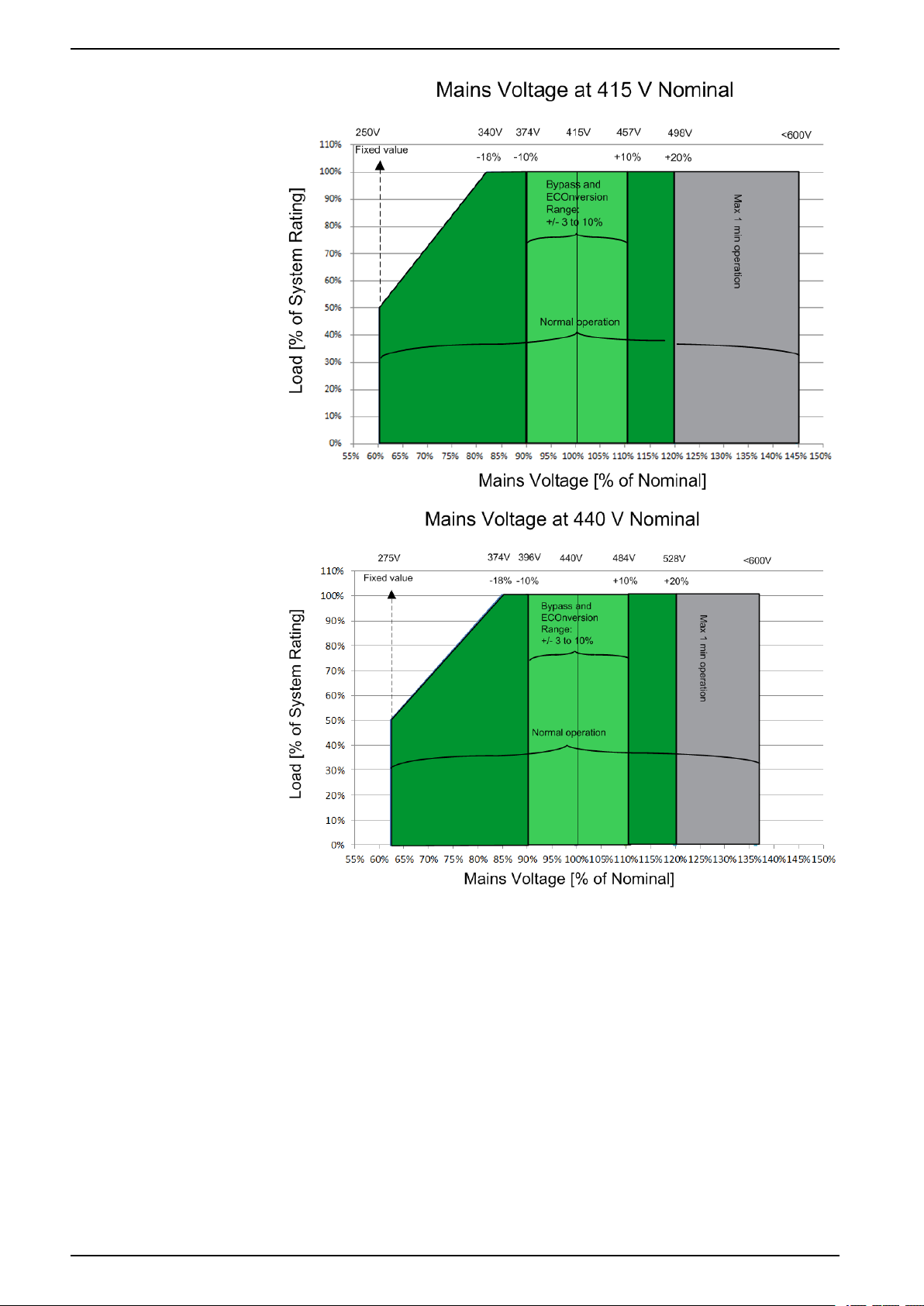
Input Voltage Window
990-5850F-001 13
Page 14
380 V, 400 V, 415 V, and 440 V UPS System Technical Data
14 990-5850F-001
Page 15
Technical Data 380 V, 400 V, 415 V, and 440 V UPS System
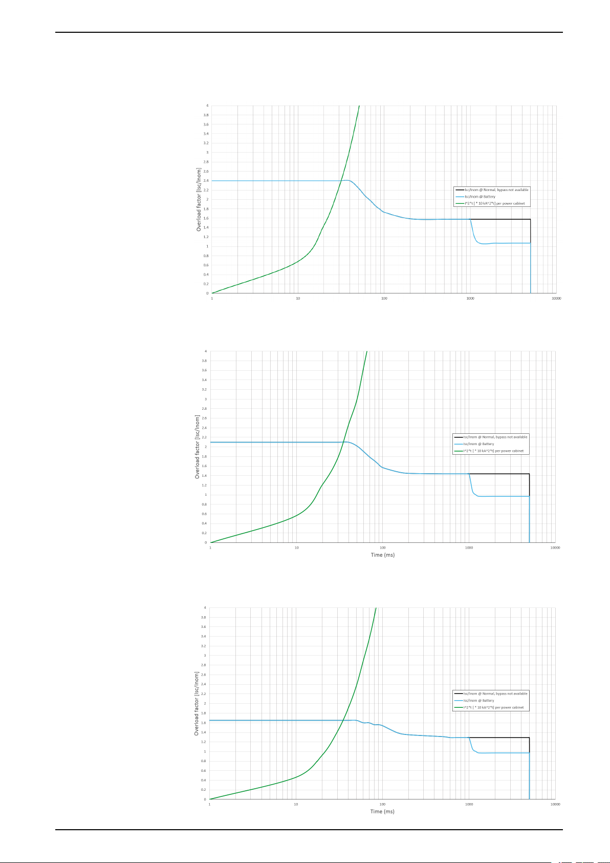
Inverter Short-Circuit Capabilities (Bypass not Available)
IK1 – Short-Circuit between a Phase and Neutral
IK2 – Short-Circuit between Two Phases
IK3 – Short-Circuit between All Three Phases
990-5850F-001 15
Page 16
380 V, 400 V, 415 V, and 440 V UPS System Technical Data
Efficiency for UPSs with 1250 kW I/O Cabinet
Efficiency for a 500 kW UPS
Normal operation
Voltage (V) 380 400 415 440 V 380 400 415 440 V
25% load 96.0% 95.2% 95.2% 95.2% 97.4% 96.2% 96.3% 96.8%
50% load 96.1% 95.7% 95.7% 95.8% 99.0% 98.7% 98.8% 98.6%
75% load 95.8% 95.6% 95.6% 95.8% 99.0% 98.8% 98.8% 98.8%
100% load 95.6% 95.5% 95.6% 95.8% 99.2% 99.0% 99.0% 99.0%
ECOnversion
Voltage (V) 380 400 415 440 V 380 400 415 440 V
25% load 99.0% 98.3% 98.4% 97.7% 96.7% 96.5% 96.6% 96.6%
50% load 98.4% 98.5% 98.1% 98.2% 96.7% 96.7% 96.5% 96.5%
75% load 99.0% 98.9% 98.9% 98.8% 94.4% 96.4% 96.3% 96.3%
100% load 99.0% 99.2% 99.2% 99.1% 96.0% 95.8% 95.5% 95.5%
ECO mode
Battery operation
Efficiency for a 625 kW UPS
Normal operation
Voltage (V) 380 400 415 440 V 380 400 415 440 V
25% load 95.1% 95.2% 95.2% 95.2% 98.0% 97.6% 97.5% 97.5%
50% load 95.7% 95.7% 95.7% 96.0% 98.9% 98.7% 98.6% 98.6%
75% load 95.6% 95.6% 95.6% 96.0% 99.0% 98.8% 98.8% 98.8%
100% load 94.9% 95.5% 95.6% 95.9% 98.9% 98.8% 98.8% 98.9%
ECO mode
ECOnversion
Voltage (V) 380 400 415 440 V 380 400 415 440 V
25% load 97.1% 97.1% 98.0% 97.6% 96.9% 96.9% 96.6% 96.6%
50% load 98.4% 98.4% 98.4% 98.4% 96.3% 96.4% 96.5% 96.5%
75% load 98.7% 98.7% 98.7% 98.7% 96.3% 96.3% 96.3% 96.3%
100% load 98.8% 98.8% 98.8% 98.9% 96.1% 96.2% 95.5% 95.5%
Battery operation
Efficiency for a 750 kW UPS
Normal operation
Voltage (V) 380 400 415 440 V 380 400 415 440 V
25% load 95.7% 95.4% 95.4% 95.4% 98.4% 98.0% 97.9% 97.9%
50% load 95.8% 95.8% 95.9% 96.0% 98.9% 98.7% 98.6% 98.6%
75% load 95.3% 95.4% 95.7% 95.9% 99.0% 98.8% 98.8% 98.8%
100% load 94.6% 94.9% 95.2% 95.5% 99.0% 98.9% 98.9% 98.9%
ECO mode
16 990-5850F-001
Page 17
Technical Data 380 V, 400 V, 415 V, and 440 V UPS System
ECOnversion
Voltage (V) 380 400 415 440 V 380 400 415 440 V
25% load 97.7% 97.7% 98.6% 98.2% 96.7% 96.7% 96.6% 96.6%
50% load 98.5% 98.5% 98.5% 98.5% 96.6% 96.7% 96.6% 96.6%
75% load 98.7% 98.7% 98.7% 98.7% 96.1% 96.2% 96.2% 96.2%
100% load 98.8% 98.8% 98.8% 98.9% 95.7% 95.8% 95.8% 95.8%
Battery operation
Efficiency for a 800 kW UPS
Normal operation
Voltage (V) 380 400 415 440 V 380 400 415 440 V
25% load 95.1% 95.1% 95.2% 95.2% 97.8% 97.8% 98.7% 98.7%
50% load 95.8% 95.9% 96.0% 96.1% 98.6% 98.6% 98.9% 98.9%
75% load 95.7% 95.8% 96.0% 96.1% 98.9% 98.9% 98.9% 98.9%
100% load 95.4% 95.5% 95.8% 96.1% 98.9% 99.0% 99.0% 99.0%
ECOnversion
Voltage (V) 380 400 415 440 V 380 400 415 440 V
25% load 97.5% 97.4% 97.5% 97.5% 96.2% 96.9% 97.0% 97.0%
50% load 98.5% 98.5% 98.5% 98.5% 96.4% 96.9% 96.6% 96.6%
75% load 98.8% 98.8% 98.8% 98.8% 96.3% 96.9% 96.8% 96.8%
100% load 98.9% 98.9% 99.0% 99.1% 96.0% 96.4% 96.3% 96.3%
ECO mode
Battery operation
Efficiency for a 1000 kW UPS
Normal operation
Voltage (V) 380 400 415 440 V 380 400 415 440 V
25% load 95.9% 95.6% 95.6% 95.6% 98.6% 98.2% 98.1% 98.1%
50% load 96.0% 96.0% 96.1% 96.1% 99.1% 98.9% 98.8% 98.8%
75% load 95.5% 95.6% 95.9% 95.9% 99.2% 99.0% 99.0% 99.0%
100% load 94.8% 95.1% 95.4% 95.4% 99.2% 99.1% 99.1% 99.1%
ECOnversion
Voltage (V) 380 400 415 440 V 380 400 415 440 V
25% load 97.9% 97.9% 98.8% 98.4% 96.8% 96.8% 96.7% 96.7%
50% load 98.7% 98.7% 98.7% 98.7% 96.7% 96.8% 96.7% 96.7%
75% load 98.9% 98.9% 98.9% 98.9% 96.2% 96.3% 96.3% 96.3%
100% load 99.0% 99.0% 99.0% 99.1% 95.8% 95.9% 95.9% 95.9%
ECO mode
Battery operation
990-5850F-001 17
Page 18
380 V, 400 V, 415 V, and 440 V UPS System Technical Data
Efficiency for a 1100 kW UPS
Normal operation
Voltage (V) 380 400 415 440 V 380 400 415 440 V
25% load 95.6% 95.6% 95.7% 95.6% 98.1% 98.2% 98.2% 0.0%
50% load 95.8% 96.0% 96.1% 96.1% 98.8% 98.8% 98.8% 0.0%
75% load 95.5% 95.8% 95.9% 95.9% 99.0% 99.1% 99.1% 0.0%
100% load 94.9% 95.3% 95.4% 95.4% 99.0% 99.0% 99.0% 99.1%
ECOnversion
Voltage (V) 380 400 415 440 V 380 400 415 440 V
25% load 97.8% 97.8% 97.9% 98.1% 96.4% 96.2% 96.3% 96.7%
50% load 98.7% 98.8% 98.7% 98.8% 96.6% 96.6% 96.4% 96.7%
75% load 98.8% 98.8% 98.8% 99.0% 94.5% 96.5% 96.4% 96.3%
100% load 98.6% 98.9% 98.9% 99.1% 96.0% 95.8% 95.5% 95.9%
ECO mode
Battery operation
Efficiency for a 1250 kW UPS
Normal operation
Voltage (V) 380 400 415 440 V 380 400 415 440 V
25% load 95.6% 95.6% 95.7% 95.7% 98.1% 98.2% 98.2% 98.3%
50% load 95.8% 96.0% 96.1% 96.3% 98.8% 98.8% 98.8% 98.9%
75% load 95.4% 95.7% 95.8% 96.0% 98.9% 99.0% 99.0% 99.1%
100% load 94.8% 95.2% 95.3% 95.7% 99.0% 99.0% 99.0% 99.1%
ECO mode
ECOnversion
Voltage (V) 380 400 415 440 V 380 400 415 440 V
25% load 97.9% 97.9% 98.0% 98.0% 96.7% 96.5% 96.6% 96.6%
50% load 98.7% 98.8% 98.7% 98.7% 96.7% 96.7% 96.5% 96.5%
75% load 98.9% 98.9% 98.9% 99.0% 96.4% 96.4% 96.3% 96.3%
100% load 98.7% 99.0% 99.0% 99.1% 96.0% 95.8% 95.5% 95.5%
Battery operation
Efficiency for UPSs with 1500 kW I/O Cabinet
Efficiency for a 500 kW UPS
Normal operation
Voltage (V) 380 400 415 440 V 380 400 415 440 V
25% load 96.1% 96.3% 96.3% 96.3% 98.7% 98.7% 98.7% 98.6%
50% load 96.3% 96.5% 96.5% 96.5% 99.1% 99.1% 99.1% 99.1%
75% load 96.0% 96.2% 96.2% 96.2% 99.1% 99.1% 99.1% 99.2%
100% load 95.2% 95.4% 95.4% 95.8% 99.2% 99.2% 99.2% 99.2%
ECO mode
18 990-5850F-001
Page 19
Technical Data 380 V, 400 V, 415 V, and 440 V UPS System
ECOnversion
Voltage (V) 380 400 415 440 V 380 400 415 440 V
25% load 98.5% 98.5% 98.5% 98.4% 95.9% 95.9% 95.9% 95.9%
50% load 99.1% 99.1% 99.1% 99.1% 96.4% 96.4% 96.4% 96.4%
75% load 99.1% 99.1% 99.1% 99.2% 96.0% 96.0% 96.0% 96.0%
100% load 99.1% 99.2% 99.2% 99.2% 95.6% 95.6% 95.6% 95.6%
Battery operation
Efficiency for a 750 kW UPS
Normal operation
Voltage (V) 380 400 415 440 V 380 400 415 440 V
25% load 96.0% 96.2% 96.2% 96.2% 98.6% 98.6% 98.6% 98.6%
50% load 96.1% 96.3% 96.3% 96.4% 99.0% 99.0% 99.0% 99.1%
75% load 95.7% 95.9% 95.9% 96.1% 99.1% 99.1% 99.1% 99.2%
100% load 95.0% 95.2% 95.2% 95.6% 99.1% 99.1% 99.1% 99.2%
ECOnversion
Voltage (V) 380 400 415 440 V 380 400 415 440 V
25% load 98.5% 98.5% 98.5% 98.4% 95.9% 95.9% 95.9% 95.9%
50% load 99.0% 99.0% 99.0% 99.0% 96.4% 96.4% 96.4% 96.4%
75% load 99.1% 99.1% 99.1% 99.2% 96.0% 96.0% 96.0% 96.0%
100% load 99.1% 99.1% 99.1% 99.2% 95.6% 95.6% 95.6% 95.6%
ECO mode
Battery operation
Efficiency for a 1000 kW UPS
Normal operation
Voltage (V) 380 400 415 440 V 380 400 415 440 V
25% load 95.9% 96.1% 96.1% 96.2% 98.6% 98.6% 98.6% 98.6%
50% load 96.0% 96.2% 96.2% 96.6% 99.0% 99.0% 99.0% 99.1%
75% load 95.4% 95.6% 95.6% 96.3% 99.1% 99.1% 99.1% 99.2%
100% load 94.8% 95.0% 95.0% 95.8% 99.1% 99.1% 99.1% 99.2%
ECOnversion
Voltage (V) 380 400 415 440 V 380 400 415 440 V
25% load 98.5% 98.5% 98.5% 98.3% 95.9% 96.0% 95.9% 95.9%
50% load 99.0% 99.0% 99.0% 99.0% 96.4% 96.4% 96.4% 96.4%
75% load 99.1% 99.1% 99.1% 99.1% 96.0% 96.1% 96.0% 96.0%
100% load 99.1% 99.1% 99.1% 99.1% 95.6% 95.6% 95.6% 95.6%
ECO mode
Battery operation
990-5850F-001 19
Page 20
380 V, 400 V, 415 V, and 440 V UPS System Technical Data
Efficiency for a 1250 kW UPS
Normal operation
Voltage (V) 380 400 415 440 V 380 400 415 440 V
25% load 96.0% 96.2% 96.2% 96.2% 98.8% 98.8% 98.8% 98.8%
50% load 96.1% 96.3% 96.3% 96.5% 99.1% 99.1% 99.1% 99.2%
75% load 95.6% 95.8% 95.8% 96.1% 99.2% 99.2% 99.2% 99.3%
100% load 95.0% 95.2% 95.2% 95.6% 99.3% 99.3% 99.3% 99.3%
ECOnversion
Voltage (V) 380 400 415 440 V 380 400 415 440 V
25% load 98.6% 98.6% 98.6% 98.4% 95.9% 95.9% 95.9% 95.9%
50% load 99.1% 99.1% 99.1% 99.1% 96.4% 96.4% 96.4% 96.4%
75% load 99.2% 99.2% 99.2% 99.2% 96.0% 96.0% 96.0% 96.0%
100% load 99.2% 99.2% 99.2% 99.2% 95.6% 95.6% 95.6% 95.6%
ECO mode
Battery operation
Efficiency for a 1500 kW UPS
Normal operation
Voltage (V) 380 400 415 440 V 380 400 415 440 V
25% load 96.0% 96.2% 96.2% 96.2% 98.8% 98.8% 98.8% 98.8%
50% load 96.1% 96.3% 96.3% 96.6% 99.1% 99.1% 99.1% 99.2%
75% load 95.6% 95.8% 95.8% 96.2% 99.2% 99.2% 99.2% 99.3%
100% load 95.0% 95.2% 95.2% 95.6% 99.3% 99.3% 99.3% 99.3%
ECO mode
ECOnversion
Voltage (V) 380 400 415 440 V 380 400 415 440 V
25% load 98.6% 98.6% 98.6% 98.7% 95.9% 96.1% 95.9% 95.9%
50% load 99.1% 99.1% 99.1% 99.2% 96.4% 96.4% 96.4% 96.4%
75% load 99.2% 99.2% 99.2% 99.3% 96.0% 96.0% 96.0% 96.0%
100% load 99.2% 99.2% 99.2% 99.3% 95.6% 95.6% 95.6% 95.6%
Battery operation
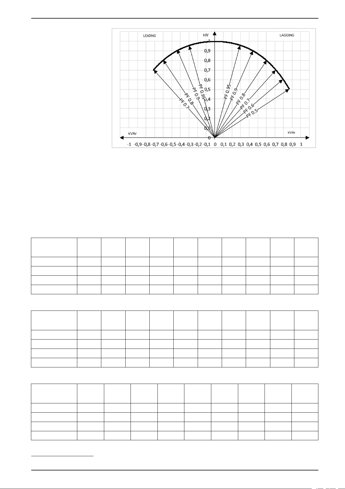
Derating Due to Load Power Factor
0.7 leading to 0.5 lagging without derating.
20 990-5850F-001
Page 21
Technical Data 380 V, 400 V, 415 V, and 440 V UPS System
Batteries
Battery Runtimes for Li-Ion Battery Cabinets LIBATTSMGGIEC
NOTE: Please allow for a tolerance of ±10% at the beginning of life.
The estimated battery runtimes are based on an environment with an ambient
temperature of 23 °C (75 °F).
500 kW UPS
Number of
LIBATTSMGGIEC
cabinets
25% load 46:30 62:30 78:30 94:30 110:00 125:00 140:00 155:00 170:00 185:00
50% load 23:00 31:00 39:00 47:00 55:00 63:00 71:00 79:00 87:00 95:00
75% load 14:30 20:00 25:30 31:00 36:00 41:30 47:00 52:00 57:30 63:00
100% load 10:30 14:30 18:30 22:30 27:00 31:00 35:00 39:00 43:00 46:30
625 kW UPS
Number of
LIBATTSMGGIEC
cabinets
25% load 37:00 49:30 62:30 75:00 88:00 100:00 110:00 125:00 135:00 150:00
50% load 18:00 24:30 31:00 37:30 43:30 50:00 56:30 63:00 69:30 76:00
75% load 11:30 16:00 20:00 24:30 29:00 33:00 37:30 41:30 46:00 50:00
100% load 5:05
3 4 5 6 7 8 9 10 11 12
3 4 5 6 7 8 9 10 11 12
1
11:30 14:30 18:00 21:00 24:30 27:30 31:00 34:00 37:00
750 kW UPS
Number of
LIBATTSMGGIEC
cabinets
25% load 41:30 52:00 63:00 73:30 84:00 94:30 105:00 115:00 125:00
50% load 20:00 25:30 31:00 36:30 41:30 47:00 52:30 57:30 63:00
75% load 13:00 16:30 20:00 23:30 27:30 31:00 34:30 38:00 41:30
100% load 9:30
1. Only partial discharge
990-5850F-001 21
4 5 6 7 8 9 10 11 12
1
12:00 14:30 17:30 20:00 22:30 25:30 28:00 31:00
Page 22
380 V, 400 V, 415 V, and 440 V UPS System Technical Data
800 kW UPS
Number of
4 5 6 7 8 9 10 11 12
LIBATTSMGGIEC
cabinets
25% load 39:00 49:00 59:00 69:00 79:00 88:30 98:30 105:00 115:00
50% load 19:00 24:00 29:00 34:00 39:00 44:00 49:00 54:30 59:30
75% load 12:00 15:30 19:00 22:00 25:30 29:00 32:30 35:30 39:00
100% load 7:45
2
11:00 14:00 16:30 19:00 21:30 24:00 26:30 29:00
1000 kW UPS
Number of
LIBATTSMGGIEC
cabinets
25% load 39:00 47:00 55:00 63:00 71:00 79:00 87:00 95:00
50% load 19:00 23:00 27:00 31:00 35:00 39:00 43:00 47:00
75% load 12:00 15:00 17:30 20:00 23:00 25:30 28:00 31:00
100% load 7:35
5 6 7 8 9 10 11 12
2
10:30 12:30 14:30 16:30 18:30 20:30 22:30
1100 kW UPS
Number of
LIBATTSMGGIEC
cabinets
25% load 35:00 42:30 50:00 57:00 64:30 71:30 79:00 86:00
50% load 17:00 21:00 24:30 28:00 32:00 35:30 39:00 43:00
75% load 11:00 13:30 16:00 18:00 20:30 23:00 25:30 28:00
100% load 1:00
5 6 7 8 9 10 11 12
2
9:50
2
11:30 13:30 15:00 17:00 19:00 20:30
1250 kW UPS
Number of
LIBATTSMGGIEC
cabinets
25% load 37:30 43:30 50:00 56:30 63:00 69:30 76:00
50% load 18:00 21:30 24:30 28:00 31:00 34:00 37:30
75% load 11:30 13:30 16:00 18:00 20:00 22:30 24:30
100% load 5:05
6 7 8 9 10 11 12
2
10:00 11:30 13:00 14:30 16:30 18:00
1500 kW UPS
Number of
LIBATTSMGGIEC
cabinets
25% load 36:30 41:30 47:00 52:30 57:30 63:00 68:30
50% load 17:30 20:00 23:00 25:30 28:30 31:00 33:30
75% load 11:00 13:00 14:30 16:30 18:30 20:00 22:00
100% load 2:25
7 8 9 10 11 12 13
2
9:30
2
10:30 12:00 13:30 14:30 16:00
2. Only partial discharge
22 990-5850F-001
Page 23
Technical Data 380 V, 400 V, 415 V, and 440 V UPS System
1500 kW UPS
Number of
LIBATTSMGGIEC
cabinets
25% load 73:30 79:00 84:00 89:30 94:30 100:00 105:00
50% load 36:30 39:00 41:30 44:30 47:00 49:30 52:30
75% load 23:30 25:30 27:00 29:00 30:30 32:30 34:30
100% load 17:30 18:30 20:00 21:30 22:30 24:00 25:30
14 15 16 17 18 19 20
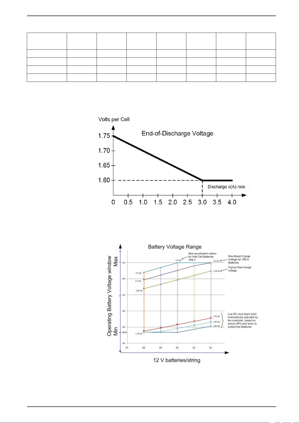
End of Discharge Voltage
The voltage is 1.6 to 1.75 per cell depending on discharge ratio.
Battery Voltage Range
990-5850F-001 23
Page 24
380 V, 400 V, 415 V, and 440 V UPS System Technical Data
Compliance
Safety IEC 62040-1: 2008-06, 1st edition Uninterruptible Power Systems (UPS) - Part 1: General and safety requirements
EMC/EMI/RFI IEC 62040-2: 2005-10, 2nd edition Uninterruptible Power Systems (UPS) - Part 2: Electromagnetic compatibility
Performance IEC 62040-3: 2011-03, 2nd edition Uninterruptible Power Systems (UPS) - Part 3: Method of specifying the
Environmental IEC 62040-4: 2013-04, 1st edition Uninterruptible Power Systems (UPS) - Part 4: Environmental aspects –
Markings CE, C-Tick
Transportation ISTA 2B
Seismic OSHPD, IBC2012 and CBC2013 to S
for UPS
EN 62040-1: 2013-01, 1st edition amendment 1
(EMC) requirements
performance and test requirements
Requirements and reporting
= 1.83 g
DS
Communication and Management
Local Area Network 100 Mbps
Extensions Two optional Network Management Cards
MODBUS MODBUS TCP/IP
Output relays 6 configurable
Input dry contacts 5 configurable
Standard control panel 7–inch touchscreen display
Audible alarm Yes
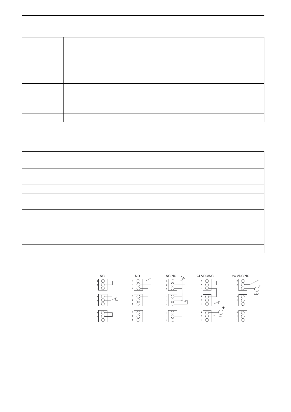
Emergency Power Off (EPO) Options:
• Normally Open (NO)
• Normally Closed (NC)
• External 24 VDC SELV
External synchronization Yes
Battery monitoring Yes — string level monitoring
EPO Connections
24 990-5850F-001
Page 25
Technical Data 380 V, 400 V, 415 V, and 440 V UPS System
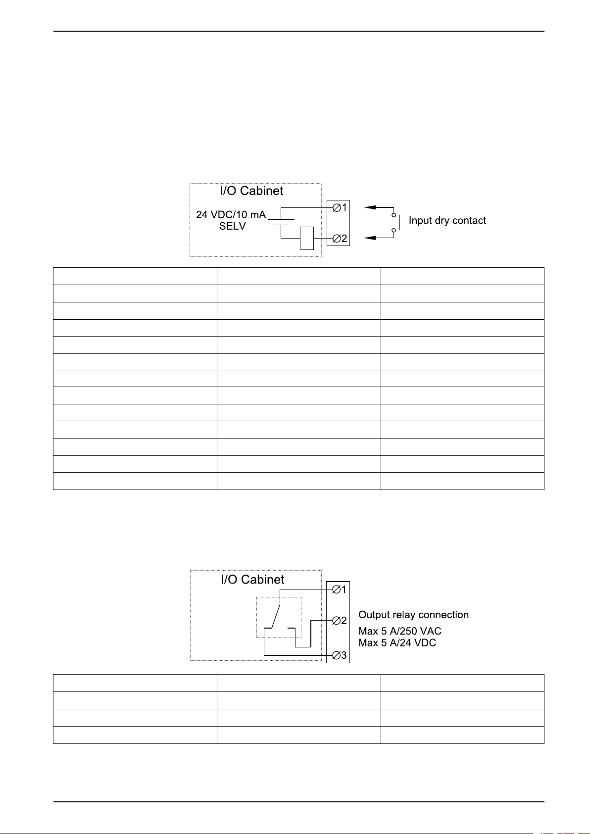
Overview of Input Contacts and Output Relays
Input Contacts
Do not connect any circuit to the input contacts unless it can be confirmed that the
circuit is Class 2/SELV.
All circuits connected must have the same 0 V reference.
The switch SW5500 on 0P6548 is used to select between internal SELV supply for
inputs (standard setting) and external supply
3
. If external supply is selected, the
supply must be connected to J5530.
Name Description Location
IN 1 (Contact 1) Configurable input contact 0P6548 terminal J5502
IN 2 (Contact 2) Configurable input contact 0P6548 terminal J5503
IN 3 (Contact 3) Configurable input contact 0P6548 terminal J5504
IN 4 (Contact 4) Configurable input contact 0P6548 terminal J5505
IN 5 (Contact 5) Configurable input contact 0P6548 terminal J5510
IN 6 UOB redundant AUX contact 0P6548 terminal J5509
IN 7 Transformer temperature switch 0P6548 terminal J5508
IN 8 External bonding contact 0P6548 terminal J5507
IN 9 Forced external synchronization input 0P6548 terminal J5506
IN 10 External synchronization requested 0P6548 terminal J5511
IN 11 Use static bypass standby 0P6548 terminal J5512
IN 14 MegaTie 0P6552 terminal J9027
4
4
4
4
4
4
4
4
4
4
4
4
Output Relays
NOTE: Maximum 250 VAC 5 A must be connected to the output relays.
All external circuitry must be fused with maximum 5 A fast acting fuses.
Name Description Location
OUT 1 (Relay 1) Configurable output relay 0P6547 terminal J4939
OUT 2 (Relay 2) Configurable output relay 0P6547 terminal J4940
OUT 3 (Relay 3) Configurable output relay 0P6547 terminal J4941
3. An external supply is useful in parallel systems where inputs are connected between different UPSs. This is to have a common reference
and to avoid cross currents.
4. Class 2/SELV wiring
990-5850F-001 25
Page 26

380 V, 400 V, 415 V, and 440 V UPS System Technical Data
Name Description Location
OUT 4 Forced external synchronization output 0P6548 terminal J5520
OUT 5 MegaTie 0P6548 terminal J5521
OUT 6 External synchronization requested output 0P6548 terminal J5522
OUT 7 UPS in inverter ON 0P6548 terminal J5523
OUT 8 (Relay 4) Configurable output relay 0P6548 terminal J5524
OUT 9 (Relay 5) Configurable output relay 0P6548 terminal J5525
OUT 10 (Relay 6) Configurable output relay 0P6548 terminal J5528
OUT 14 Bonding contactor 0P6552 terminal J9029
5
5
5
5
5
5
5
5
NOTE: Refer to the operation manual for configuration options.
5. Class 2/SELV wiring
26 990-5850F-001
Page 27
Facility Planning 380 V, 400 V, 415 V, and 440 V UPS System
Facility Planning
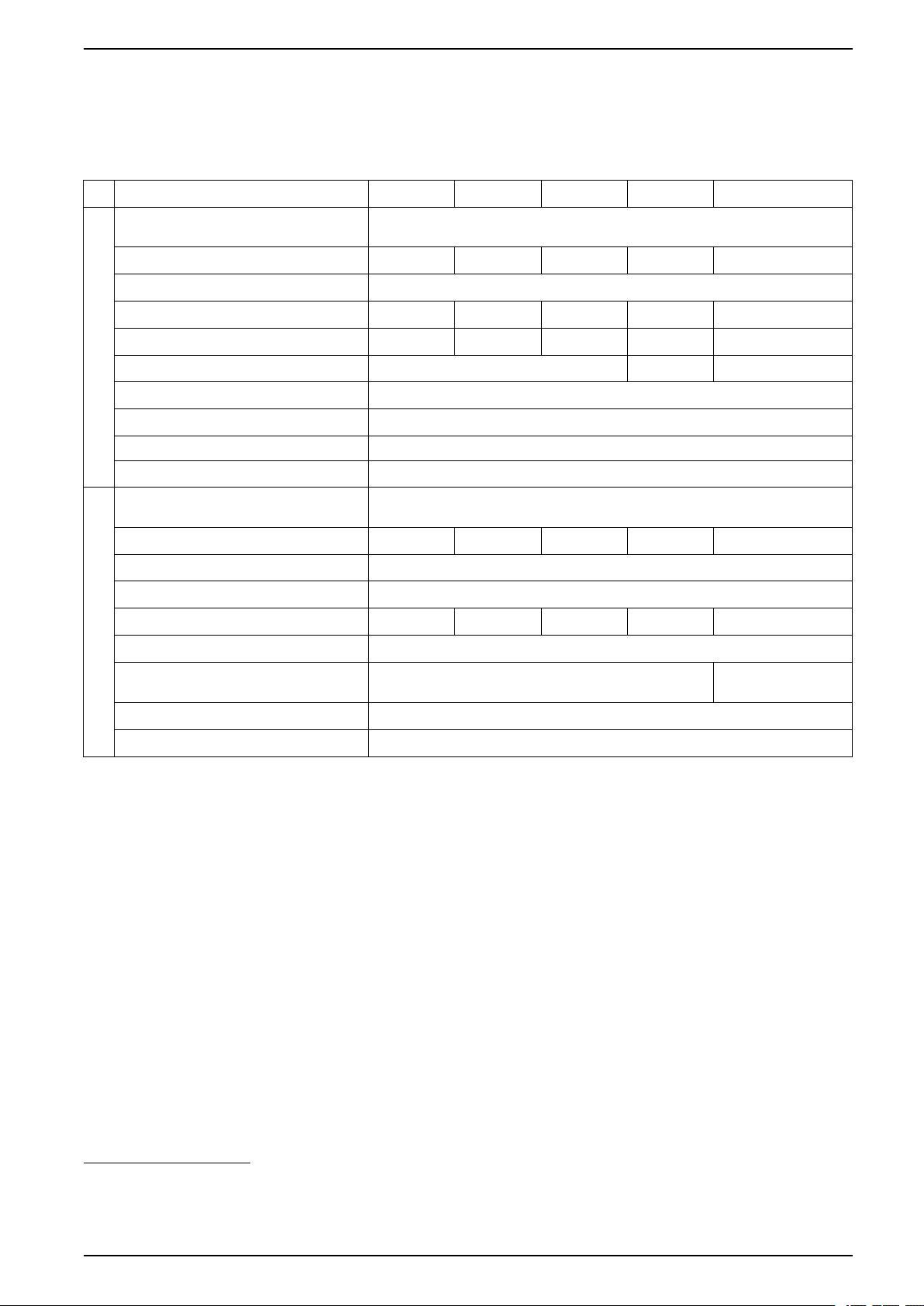
Specifications for 500 kW UPS
Voltage (V) 380 400 415 440 V 480 V
Connections IEC: L1, L2, L3, PE
Input voltage range (V)
Frequency (Hz) 40-70
Nominal input current (A) 800 760 731 685 633
Maximum input current (A)
Input current limitation (A) 890 832 760
Total harmonic distortion (THDI) <3% at 100% load, <4% at 50% load, <9% at 25% load
Input Specifications
Input power factor 0.99 at >40% load, 0.98 at >20% load, 0.97 at >10% load
Protection Contactors
Ramp-in Adaptive 1-300 seconds
Connections IEC: L1, L2, L3, N, PE or L1, L2, L3, PE
Bypass voltage range (V) 342-418 360-440 374-457 396-484 432-528
8
9
UL: L1, L2, L3 + G
340-456 340-480 353-498 374-528 408-576
886 851 819 767 728
UL: L1, L2, L3, G or L1, L2, L3, N, G
6
7
10
Frequency (Hz) 50 or 60
Frequency range (Hz) Programmable: ±0.1, ±3, ±10. Default is ±3
Nominal bypass current (A) 767 729 703 663 606
Maximum short circuit rating 100 kA RMS (conditioned by an internal molded switch with 90 kA peak magnetic trip)
Thyristor I²t (kA*s²) 9680 (1250 kW I/O)
Bypass Specifications
BF2 magnetic trip 39 kA
Protection Molded switch with trip for backfeed protection
16245 (1500 kW I/O)
9165 (1250 kW I/O)
16245 (1500 kW I/O)
6. TN, TT, and IT power distribution systems are supported.
7. WYE source – solid grounded and high resistance grounded sources are supported. Corner (line) grounding is not supported.
8. The system can operate at 600 V for 1 minute.
9. At nominal input voltage and full charge.
10. TN, TT, and IT power distribution systems with no earthed line conductors are supported.
990-5850F-001 27
Page 28
380 V, 400 V, 415 V, and 440 V UPS System Facility Planning
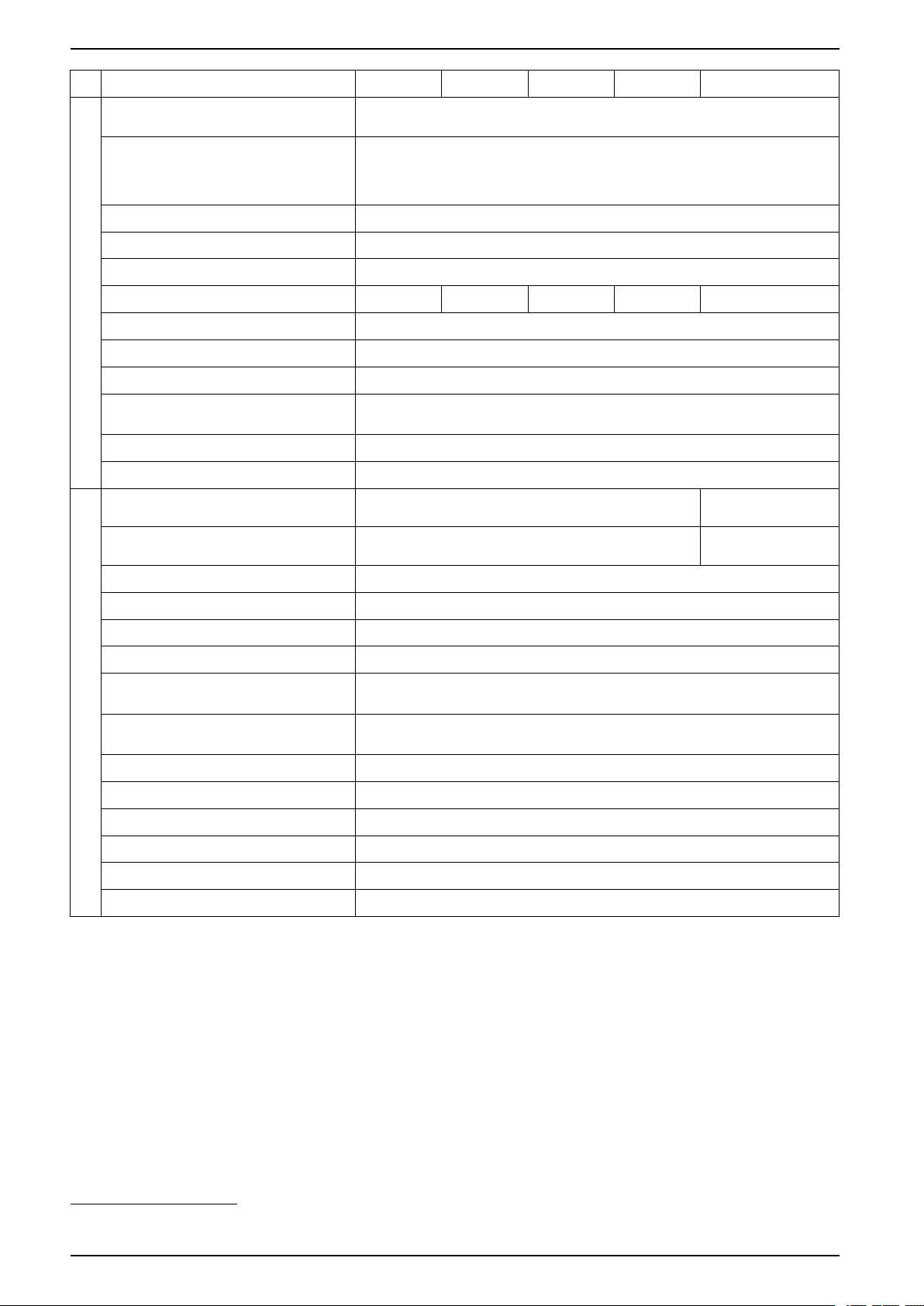
Voltage (V) 380 400 415 440 V 480 V
Connections IEC: L1, L2, L3, N, PE or L1, L2, L3, PE
UL: L1, L2, L3, G, GEC
11
or L1, L2, L3, N, G
Overload capacity Normal operation: 150% for 1 minute, 125% for 10 minutes
Battery operation: 115% for 1 minute
Bypass operation: 110%
12
continuous, 1000% for 60 milliseconds for systems with
1250 kW I/O cabinet and 100 milliseconds for systems with 1500 kW I/O cabinet
Output voltage tolerance Balanced load: ±1%, Unbalanced load: ±3%
Dynamic load response ±5% after 2 ms, ±1% after 50 ms
Output power factor 1
Nominal output current (A) 760 722 696 656 601
Total harmonic distortion (THDU) <2% at 100% linear load, <3% at 100% non-linear load
Output frequency (Hz) 50/60 (synchronized to bypass), 50/60 Hz ±0.1% (free-running)
Output Specifications
Slew rate (Hz/sec) Programmable: 0.25, 0.5, 1, 2, 4, 6
Output performance classification
Double-conversion: VFI-SS-111
(according to IEC/ EN62040-3)
Load crest factor Up to 3 (THDU < 5%)
Load power factor 0.7 leading to 0.5 lagging without derating
Charging power in % of output power 35% at ≤ 80% load, 12% at 100% load 40% at ≤ 80% load,
15% at 100% load
Maximum charging power (kW) 60 at 100% load, 175 at <80% load 75 at 100% load, 200
at 80% load
Nominal battery voltage (VDC) 480
Nominal float voltage (VDC) 546
End of discharge voltage (full load) (VDC) 384
End of discharge voltage (no load) (VDC) 420
Battery current at full load and nominal
1090
battery voltage (A)
Battery current at full load and minimum
1362
battery voltage (A)
Battery Specifications
Maximum battery backup time Unlimited
Temperature compensation (per cell) -3.3 mV per °C for T ≥ 25 °C, 0 mV per °C for T < 25 °C
Ripple current < 5% C20 (5 minutes backup time)
Battery test Manual/automatic (selectable)
Deep discharge protection Yes
Recharge according to battery temperature Yes
11. Per NEC 250.30.
12. 125% for 480 V.
28 990-5850F-001
Page 29
Facility Planning 380 V, 400 V, 415 V, and 440 V UPS System
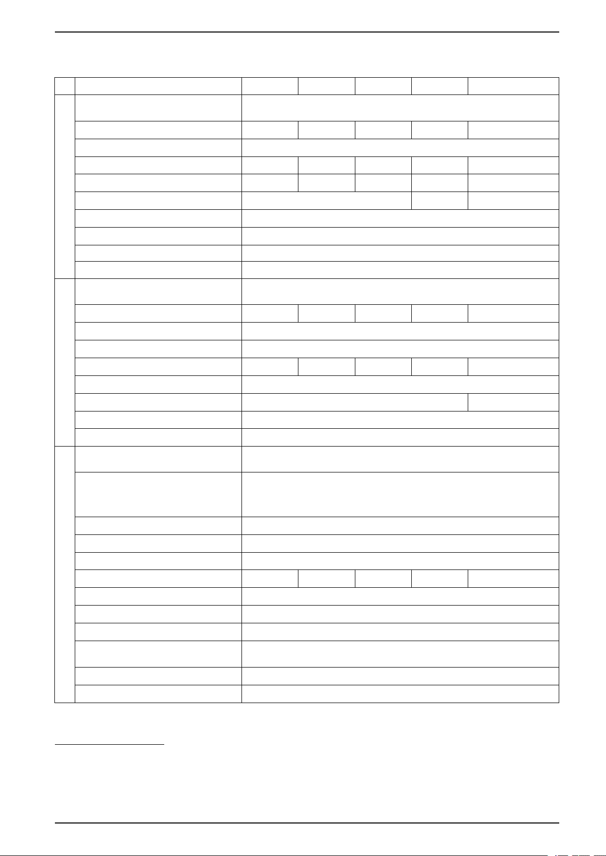
Specifications for 625 kW UPS
Voltage (V) 380 400 415 440 V 480 V
Connections IEC: L1, L2, L3, PE
UL: L1, L2, L3 + G
Input voltage range (V)
15
340-456 340-480 353-498 374-528 408-576
Frequency (Hz) 40-70
Nominal input current (A) 1001 950 914 853 791
Maximum input current (A)
16
1107 1063 1024 956 910
Input current limitation (A) 1113 1040 950
Total harmonic distortion (THDI) <3% at 100% load, <4% at 50% load, <9% at 25% load
Input Specifications
Input power factor 0.99 at >40% load, 0.98 at >20% load, 0.97 at >10% load
Protection Contactors
Ramp-in Adaptive 1-300 seconds
Connections IEC: L1, L2, L3, N, PE or L1, L2, L3, PE
UL: L1, L2, L3, G or L1, L2, L3, N, G
Bypass voltage range (V) 342-418 360-440 374-457 396-484 432-528
13
14
17
Frequency (Hz) 50 or 60
Frequency range (Hz) Programmable: ±0.1, ±3, ±10. Default is ±3
Nominal bypass current (A) 959 911 878 828 757
Maximum short circuit rating 100 kA RMS (conditioned by an internal molded switch with 90 kA peak magnetic trip)
Thyristor I²t (kA*s²) 9680 (1250 kW I/O) 9165 (1250 kW I/O)
Bypass Specifications
BF2 magnetic trip 39 kA
Protection Molded switch with trip for backfeed protection
Connections IEC: L1, L2, L3, N, PE or L1, L2, L3, PE
UL: L1, L2, L3, G, GEC
18
or L1, L2, L3, N, G
Overload capacity Normal operation: 150% for 1 minute, 125% for 10 minutes
Battery operation: 115% for 1 minute
Bypass operation: 110%
19
continuous, 1000% for 60 milliseconds for systems with
1250 kW I/O cabinet and 100 milliseconds for systems with 1500 kW I/O cabinet
Output voltage tolerance Balanced load: ±1%, Unbalanced load: ±3%
Dynamic load response ±5% after 2 ms, ±1% after 50 ms
Output power factor 1
Nominal output current (A) 950 902 870 820 752
Total harmonic distortion (THDU) <2% at 100% linear load, <3% at 100% non-linear load
Output frequency (Hz) 50/60 (synchronized to bypass), 50/60 Hz ±0.1% (free-running)
Output Specifications
Slew rate (Hz/sec) Programmable: 0.25, 0.5, 1, 2, 4, 6
Output performance classification
Double-conversion: VFI-SS-111
(according to IEC/ EN62040-3)
Load crest factor Up to 3 (THDU < 5%)
Load power factor 0.7 leading to 0.5 lagging without derating
13. TN, TT, and IT power distribution systems are supported.
14. WYE source – solid grounded and high resistance grounded sources are supported. Corner (line) grounding is not supported.
15. The system can operate at 600 V for 1 minute.
16. At nominal input voltage and full charge.
17. TN, TT, and IT power distribution systems with no earthed line conductors are supported.
18. Per NEC 250.30.
19. 125% for 480 V.
990-5850F-001 29
Page 30
380 V, 400 V, 415 V, and 440 V UPS System Facility Planning
Voltage (V) 380 400 415 440 V 480 V
Charging power in % of output power 35% at ≤ 80% load, 12% at 100% load 40% at ≤ 80% load,
Maximum charging power (kW) 75 at 100% load, 218.75 at <80% load 93.75 at 100% load,
Nominal battery voltage (VDC) 480
Nominal float voltage (VDC) 546
End of discharge voltage (full load) (VDC) 384
End of discharge voltage (no load) (VDC) 420
Battery current at full load and nominal
battery voltage (A)
Battery current at full load and minimum
battery voltage (A)
Battery Specifications
Maximum battery backup time Unlimited
Temperature compensation (per cell) -3.3 mV per °C for T ≥ 25 °C, 0 mV per °C for T < 25 °C
Ripple current < 5% C20 (5 minutes backup time)
Battery test Manual/automatic (selectable)
Deep discharge protection Yes
Recharge according to battery temperature Yes
1362
1703
15% at 100% load
250 at 80% load
30 990-5850F-001
Page 31
Facility Planning 380 V, 400 V, 415 V, and 440 V UPS System
Specifications for 750 kW UPS
Voltage (V) 380 400 415 440 V 480 V
Connections IEC: L1, L2, L3, PE
UL: L1, L2, L3 + G
Input voltage range (V)
22
340-456 340-480 353-498 374-528 408-576
Frequency (Hz) 40-70
Nominal input current (A) 1201 1139 1097 1029 950
Maximum input current (A)
23
1328 1276 1229 1153 1092
Input current limitation (A) 1335 1248 1140
Total harmonic distortion (THDI) <3% at 100% load, <4% at 50% load, <9% at 25% load
Input Specifications
Input power factor 0.99 at >40% load, 0.98 at >20% load, 0.97 at >10% load
Protection Contactors
Ramp-in Adaptive 1-300 seconds
Connections IEC: L1, L2, L3, N, PE or L1, L2, L3, PE
UL: L1, L2, L3, G or L1, L2, L3, N, G
Bypass voltage range (V) 342-418 360-440 374-457 396-484 432-528
20
21
24
Frequency (Hz) 50 or 60
Frequency range (Hz) Programmable: ±0.1, ±3, ±10. Default is ±3
Nominal bypass current (A) 1151 1093 1054 994 909
Maximum short circuit rating 100 kA RMS (conditioned by an internal molded switch with 90 kA peak magnetic trip)
Thyristor I²t (kA*s²) 9680 (1250 kW I/O)
Bypass Specifications
16245 (1500 kW I/O)
9165 (1250 kW I/O)
16245 (1500 kW I/O)
BF2 magnetic trip 39 kA
Protection Molded switch with trip for backfeed protection
Connections IEC: L1, L2, L3, N, PE or L1, L2, L3, PE
UL: L1, L2, L3, G, GEC
25
or L1, L2, L3, N, G
Overload capacity Normal operation: 150% for 1 minute, 125% for 10 minutes
Battery operation: 115% for 1 minute
Bypass operation: 110%
26
continuous, 1000% for 60 milliseconds for systems with
1250 kW I/O cabinet and 100 milliseconds for systems with 1500 kW I/O cabinet
Output voltage tolerance Balanced load: ±1%, Unbalanced load: ±3%
Dynamic load response ±5% after 2 ms, ±1% after 50 ms
Output power factor 1
Nominal output current (A) 1140 1083 1043 984 902
Total harmonic distortion (THDU) <2% at 100% linear load, <3% at 100% non-linear load
Output frequency (Hz) 50/60 (synchronized to bypass), 50/60 Hz ±0.1% (free-running)
Output Specifications
Slew rate (Hz/sec) Programmable: 0.25, 0.5, 1, 2, 4, 6
Output performance classification
Double-conversion: VFI-SS-111
(according to IEC/ EN62040-3)
Load crest factor Up to 3 (THDU < 5%)
Load power factor 0.7 leading to 0.5 lagging without derating
20. TN, TT, and IT power distribution systems are supported.
21. WYE source – solid grounded and high resistance grounded sources are supported. Corner (line) grounding is not supported.
22. The system can operate at 600 V for 1 minute.
23. At nominal input voltage and full charge.
24. TN, TT, and IT power distribution systems with no earthed line conductors are supported.
25. Per NEC 250.30.
26. 125% for 480 V.
990-5850F-001 31
Page 32
380 V, 400 V, 415 V, and 440 V UPS System Facility Planning
Voltage (V) 380 400 415 440 V 480 V
Charging power in % of output power 35% at ≤ 80% load, 12% at 100% load 40% at ≤ 80% load,
Maximum charging power (kW) 90 at 100% load, 262 at <80% load 112.5 at 100% load,
Nominal battery voltage (VDC) 480
Nominal float voltage (VDC) 546
End of discharge voltage (full load) (VDC) 384
End of discharge voltage (no load) (VDC) 420
Battery current at full load and nominal
battery voltage (A)
Battery current at full load and minimum
battery voltage (A)
Battery Specifications
Maximum battery backup time Unlimited
Temperature compensation (per cell) -3.3 mV per °C for T ≥ 25 °C, 0 mV per °C for T < 25 °C
Ripple current < 5% C20 (5 minutes backup time)
Battery test Manual/automatic (selectable)
Deep discharge protection Yes
Recharge according to battery temperature Yes
1634
2043
15% at 100% load
300 at 80% load
32 990-5850F-001
Page 33
Facility Planning 380 V, 400 V, 415 V, and 440 V UPS System
Specifications for 800 kW UPS
Voltage (V) 380 400 415 440 V 480 V
Connections IEC: L1, L2, L3, PE
UL: L1, L2, L3 + G
Input voltage range (V)
29
340-456 340-480 353-498 374-528 408-576
Frequency (Hz) 40-70
Nominal input current (A) 1281 1215 1170 1098 1013
Maximum input current (A)
30
1417 1361 1311 1230 1165
Input current limitation (A) 1424 1331 1216
Total harmonic distortion (THDI) <3% at 100% load, <4% at 50% load, <9% at 25% load
Input Specifications
Input power factor 0.99 at >40% load, 0.98 at >20% load, 0.97 at >10% load
Protection Contactors
Ramp-in Adaptive 1-300 seconds
Connections IEC: L1, L2, L3, N, PE or L1, L2, L3, PE
UL: L1, L2, L3, G or L1, L2, L3, N, G
Bypass voltage range (V) 342-418 360-440 374-457 396-484 432-528
27
28
31
Frequency (Hz) 50 or 60
Frequency range (Hz) Programmable: ±0.1, ±3, ±10. Default is ±3
Nominal bypass current (A) 1228 1166 1124 1060 969
Maximum short circuit rating 100 kA RMS (conditioned by an internal molded switch with 90 kA peak magnetic trip)
Thyristor I²t (kA*s²) 9680 (1250 kW I/O) 9165 (1250 kW I/O)
Bypass Specifications
BF2 magnetic trip 39 kA
Protection Molded switch with trip for backfeed protection
Connections IEC: L1, L2, L3, N, PE or L1, L2, L3, PE
UL: L1, L2, L3, G, GEC
32
or L1, L2, L3, N, G
Overload capacity Normal operation: 150% for 1 minute, 125% for 10 minutes
Battery operation: 115% for 1 minute
Bypass operation: 110%
33
continuous, 1000% for 60 milliseconds for systems with
1250 kW I/O cabinet and 100 milliseconds for systems with 1500 kW I/O cabinet
Output voltage tolerance Balanced load: ±1%, Unbalanced load: ±3%
Dynamic load response ±5% after 2 ms, ±1% after 50 ms
Output power factor 1
Nominal output current (A) 1216 1155 1113 1050 962
Total harmonic distortion (THDU) <2% at 100% linear load, <3% at 100% non-linear load
Output frequency (Hz) 50/60 (synchronized to bypass), 50/60 Hz ±0.1% (free-running)
Output Specifications
Slew rate (Hz/sec) Programmable: 0.25, 0.5, 1, 2, 4, 6
Output performance classification
Double-conversion: VFI-SS-111
(according to IEC/ EN62040-3)
Load crest factor Up to 3 (THDU < 5%)
Load power factor 0.7 leading to 0.5 lagging without derating
27. TN, TT, and IT power distribution systems are supported.
28. WYE source – solid grounded and high resistance grounded sources are supported. Corner (line) grounding is not supported.
29. The system can operate at 600 V for 1 minute.
30. At nominal input voltage and full charge.
31. TN, TT, and IT power distribution systems with no earthed line conductors are supported.
32. Per NEC 250.30.
33. 125% for 480 V.
990-5850F-001 33
Page 34
380 V, 400 V, 415 V, and 440 V UPS System Facility Planning
Voltage (V) 380 400 415 440 V 480 V
Charging power in % of output power 35% at ≤ 80% load, 12% at 100% load 40% at ≤ 80% load,
Maximum charging power (kW) 96 at 100% load, 280 at <80% load 120 at 100% load, 320
Nominal battery voltage (VDC) 480
Nominal float voltage (VDC) 546
End of discharge voltage (full load) (VDC) 384
End of discharge voltage (no load) (VDC) 420
Battery current at full load and nominal
battery voltage (A)
Battery current at full load and minimum
battery voltage (A)
Battery Specifications
Maximum battery backup time Unlimited
Temperature compensation (per cell) -3.3 mV per °C for T ≥ 25 °C, 0 mV per °C for T < 25 °C
Ripple current < 5% C20 (5 minutes backup time)
Battery test Manual/automatic (selectable)
Deep discharge protection Yes
Recharge according to battery temperature Yes
1743
2179
15% at 100% load
at 80% load
34 990-5850F-001
Page 35
Facility Planning 380 V, 400 V, 415 V, and 440 V UPS System
Specifications for 1000 kW UPS
Voltage (V) 380 400 415 440 V 480 V
Connections IEC: L1, L2, L3, PE
UL: L1, L2, L3 + G
Input voltage range (V)
36
340-456 340-480 353-498 374-528 408-576
Frequency (Hz) 40-70
Nominal input current (A) 1601 1519 1463 1370 1266
Maximum input current (A)
37
1771 1702 1638 1534 1456
Input current limitation (A) 1780 1664 1520
Total harmonic distortion (THDI) <3% at 100% load, <4% at 50% load, <9% at 25% load
Input Specifications
Input power factor 0.99 at >40% load, 0.98 at >20% load, 0.97 at >10% load
Protection Contactors
Ramp-in Adaptive 1-300 seconds
Connections IEC: L1, L2, L3, N, PE or L1, L2, L3, PE
UL: L1, L2, L3, G or L1, L2, L3, N, G
Bypass voltage range (V) 342-418 360-440 374-457 396-484 432-528
34
35
38
Frequency (Hz) 50 or 60
Frequency range (Hz) Programmable: ±0.1, ±3, ±10. Default is ±3
Nominal bypass current (A) 1535 1458 1405 1325 1211
Maximum short circuit rating 100 kA RMS (conditioned by an internal molded switch with 90 kA peak magnetic trip)
Thyristor I²t (kA*s²) 9680 (1250 kW I/O)
Bypass Specifications
16245 (1500 kW I/O)
9165 (1250 kW I/O)
16245 (1500 kW I/O)
BF2 magnetic trip 39 kA
Protection Molded switch with trip for backfeed protection
Connections IEC: L1, L2, L3, N, PE or L1, L2, L3, PE
UL: L1, L2, L3, G, GEC
39
or L1, L2, L3, N, G
Overload capacity Normal operation: 150% for 1 minute, 125% for 10 minutes
Battery operation: 115% for 1 minute
Bypass operation: 110%
40
continuous, 1000% for 60 milliseconds for systems with
1250 kW I/O cabinet and 100 milliseconds for systems with 1500 kW I/O cabinet
Output voltage tolerance Balanced load: ±1%, Unbalanced load: ±3%
Dynamic load response ±5% after 2 ms, ±1% after 50 ms
Output power factor 1
Nominal output current (A) 1519 1443 1391 1312 1203
Total harmonic distortion (THDU) <2% at 100% linear load, <3% at 100% non-linear load
Output frequency (Hz) 50/60 (synchronized to bypass), 50/60 Hz ±0.1% (free-running)
Output Specifications
Slew rate (Hz/sec) Programmable: 0.25, 0.5, 1, 2, 4, 6
Output performance classification
Double-conversion: VFI-SS-111
(according to IEC/ EN62040-3)
Load crest factor Up to 3 (THDU < 5%)
Load power factor 0.7 leading to 0.5 lagging without derating
34. TN, TT, and IT power distribution systems are supported.
35. WYE source – solid grounded and high resistance grounded sources are supported. Corner (line) grounding is not supported.
36. The system can operate at 600 V for 1 minute.
37. At nominal input voltage and full charge.
38. TN, TT, and IT power distribution systems with no earthed line conductors are supported.
39. Per NEC 250.30.
40. 125% for 480 V.
990-5850F-001 35
Page 36
380 V, 400 V, 415 V, and 440 V UPS System Facility Planning
Voltage (V) 380 400 415 440 V 480 V
Charging power in % of output power 35% at ≤ 80% load, 12% at 100% load 40% at ≤ 80% load,
Maximum charging power (kW) 120 at 100% load, 350 at <80% load 150 at 100% load, 400
Nominal battery voltage (VDC) 480
Nominal float voltage (VDC) 546
End of discharge voltage (full load) (VDC) 384
End of discharge voltage (no load) (VDC) 420
Battery current at full load and nominal
battery voltage (A)
Battery current at full load and minimum
battery voltage (A)
Battery Specifications
Maximum battery backup time Unlimited
Temperature compensation (per cell) -3.3 mV per °C for T ≥ 25 °C, 0 mV per °C for T < 25 °C
Ripple current < 5% C20 (5 minutes backup time)
Battery test Manual/automatic (selectable)
Deep discharge protection Yes
Recharge according to battery temperature Yes
2179
2724
15% at 100% load
at <80% load
36 990-5850F-001
Page 37
Facility Planning 380 V, 400 V, 415 V, and 440 V UPS System
Specifications for 1100 kW UPS
Voltage (V) 380 400 415 440 V 480 V
Connections IEC: L1, L2, L3, PE
UL: L1, L2, L3 + G
Input voltage range (V)
43
340-456 340-480 353-498 374-528 408-576
Frequency (Hz) 40-70
Nominal input current (A) 1761 1671 1609 1510 1393
Maximum input current (A)
44
1948 1872 1802 1691 1602
Input current limitation (A) 1958 1830 1672
Total harmonic distortion (THDI) <3% at 100% load, <4% at 50% load, <9% at 25% load
Input Specifications
Input power factor 0.99 at >40% load, 0.98 at >20% load, 0.97 at >10% load
Protection Contactors
Ramp-in Adaptive 1-300 seconds
Connections IEC: L1, L2, L3, N, PE or L1, L2, L3, PE
UL: L1, L2, L3, G or L1, L2, L3, N, G
Bypass voltage range (V) 342-418 360-440 374-457 396-484 432-528
41
42
45
Frequency (Hz) 50 or 60
Frequency range (Hz) Programmable: ±0.1, ±3, ±10. Default is ±3
Nominal bypass current (A) 1688 1604 1546 1458 1332
Maximum short circuit rating 100 kA RMS (conditioned by an internal molded switch with 90 kA peak magnetic trip)
Thyristor I²t (kA*s²) 9680 (1250 kW I/O) 9165 (1250 kW I/O)
Bypass Specifications
BF2 magnetic trip 39 kA
Protection Molded switch with trip for backfeed protection
Connections IEC: L1, L2, L3, N, PE or L1, L2, L3, PE
UL: L1, L2, L3, G, GEC
46
or L1, L2, L3, N, G
Overload capacity Normal operation: 150% for 1 minute, 125% for 10 minutes
Battery operation: 115% for 1 minute
Bypass operation: 110%
47
continuous, 1000% for 60 milliseconds for systems with
1250 kW I/O cabinet and 100 milliseconds for systems with 1500 kW I/O cabinet
Output voltage tolerance Balanced load: ±1%, Unbalanced load: ±3%
Dynamic load response ±5% after 2 ms, ±1% after 50 ms
Output power factor 1
Nominal output current (A) 1671 1588 1530 1443 1323
Total harmonic distortion (THDU) <2% at 100% linear load, <3% at 100% non-linear load
Output frequency (Hz) 50/60 (synchronized to bypass), 50/60 Hz ±0.1% (free-running)
Output Specifications
Slew rate (Hz/sec) Programmable: 0.25, 0.5, 1, 2, 4, 6
Output performance classification
Double-conversion: VFI-SS-111
(according to IEC/ EN62040-3)
Load crest factor Up to 3 (THDU < 5%)
Load power factor 0.7 leading to 0.5 lagging without derating
41. TN, TT, and IT power distribution systems are supported.
42. WYE source – solid grounded and high resistance grounded sources are supported. Corner (line) grounding is not supported.
43. The system can operate at 600 V for 1 minute.
44. At nominal input voltage and full charge.
45. TN, TT, and IT power distribution systems with no earthed line conductors are supported.
46. Per NEC 250.30.
47. 125% for 480 V.
990-5850F-001 37
Page 38
380 V, 400 V, 415 V, and 440 V UPS System Facility Planning
Voltage (V) 380 400 415 440 V 480 V
Charging power in % of output power 35% at ≤ 80% load, 12% at 100% load 40% at ≤ 80% load,
Maximum charging power (kW) 132 at 100% load, 385 at <80% load 165 at 100% load, 440
Nominal battery voltage (VDC) 480
Nominal float voltage (VDC) 546
End of discharge voltage (full load) (VDC) 384
End of discharge voltage (no load) (VDC) 420
Battery current at full load and nominal
battery voltage (A)
Battery current at full load and minimum
battery voltage (A)
Battery Specifications
Maximum battery backup time Unlimited
Temperature compensation (per cell) -3.3 mV per °C for T ≥ 25 °C, 0 mV per °C for T < 25 °C
Ripple current < 5% C20 (5 minutes backup time)
Battery test Manual/automatic (selectable)
Deep discharge protection Yes
Recharge according to battery temperature Yes
2397
2996
15% at 100% load
at <80% load
38 990-5850F-001
Page 39
Facility Planning 380 V, 400 V, 415 V, and 440 V UPS System
Specifications for 1250 kW UPS
Voltage (V) 380 400 415 440 V 480 V
Connections IEC: L1, L2, L3, PE
UL: L1, L2, L3 + G
Input voltage range (V)
50
340-456 340-480 353-498 374-528 408-576
Frequency (Hz) 40-70
Nominal input current (A) 2001 1899 1828 1716 1583
Maximum input current (A)
51
2214 2127 2048 1922 1820
Input current limitation (A) 2225 2080 1900
Total harmonic distortion (THDI) <3% at 100% load, <4% at 50% load, <9% at 25% load
Input Specifications
Input power factor 0.99 at >40% load, 0.98 at >20% load, 0.97 at >10% load
Protection Contactors
Ramp-in Adaptive 1-300 seconds
Connections IEC: L1, L2, L3, N, PE or L1, L2, L3, PE
UL: L1, L2, L3, G or L1, L2, L3, N, G
Bypass voltage range (V) 342-418 360-440 374-457 396-484 432-528
48
49
52
Frequency (Hz) 50 or 60
Frequency range (Hz) Programmable: ±0.1, ±3, ±10. Default is ±3
Nominal bypass current (A) 1918 1822 1757 1657 1514
Maximum short circuit rating 100 kA RMS (conditioned by an internal molded switch with 90 kA peak magnetic trip)
Thyristor I²t (kA*s²) 9680 (1250 kW I/O)
Bypass Specifications
16245 (1500 kW I/O)
9165 (1250 kW I/O)
16245 (1500 kW I/O)
BF2 magnetic trip 39 kA
Protection Molded switch with trip for backfeed protection
Connections IEC: L1, L2, L3, N, PE or L1, L2, L3, PE
UL: L1, L2, L3, G, GEC
53
or L1, L2, L3, N, G
Overload capacity Normal operation: 150% for 1 minute, 125% for 10 minutes
Battery operation: 115% for 1 minute
Bypass operation: 110%
54
continuous, 1000% for 60 milliseconds for systems with
1250 kW I/O cabinet and 100 milliseconds for systems with 1500 kW I/O cabinet
Output voltage tolerance Balanced load: ±1%, Unbalanced load: ±3%
Dynamic load response ±5% after 2 ms, ±1% after 50 ms
Output power factor 1
Nominal output current (A) 1899 1804 1739 1640 1504
Total harmonic distortion (THDU) <2% at 100% linear load, <3% at 100% non-linear load
Output frequency (Hz) 50/60 (synchronized to bypass), 50/60 Hz ±0.1% (free-running)
Output Specifications
Slew rate (Hz/sec) Programmable: 0.25, 0.5, 1, 2, 4, 6
Output performance classification
Double-conversion: VFI-SS-111
(according to IEC/ EN62040-3)
Load crest factor Up to 3 (THDU < 5%)
Load power factor 0.7 leading to 0.5 lagging without derating
48. TN, TT, and IT power distribution systems are supported.
49. WYE source – solid grounded and high resistance grounded sources are supported. Corner (line) grounding is not supported.
50. The system can operate at 600 V for 1 minute.
51. At nominal input voltage and full charge.
52. TN, TT, and IT power distribution systems with no earthed line conductors are supported.
53. Per NEC 250.30.
54. 125% for 480 V.
990-5850F-001 39
Page 40
380 V, 400 V, 415 V, and 440 V UPS System Facility Planning
Voltage (V) 380 400 415 440 V 480 V
Charging power in % of output power 35% at ≤ 80% load, 12% at 100% load 40% at ≤ 80% load,
Maximum charging power (kW) 150 at 100% load, 437 at <80% load 187.5 at 100% load,
Nominal battery voltage (VDC) 480
Nominal float voltage (VDC) 546
End of discharge voltage (full load) (VDC) 384
End of discharge voltage (no load) (VDC) 420
Battery current at full load and nominal
battery voltage (A)
Battery current at full load and minimum
battery voltage (A)
Battery Specifications
Maximum battery backup time 1 hour
Temperature compensation (per cell) -3.3 mV per °C for T ≥ 25 °C, 0 mV per °C for T < 25 °C
Ripple current < 5% C20 (5 minutes backup time)
Battery test Manual/automatic (selectable)
Deep discharge protection Yes
Recharge according to battery temperature Yes
2724
3405
15% at 100% load
500 at <80% load
40 990-5850F-001
Page 41
Facility Planning 380 V, 400 V, 415 V, and 440 V UPS System
Specifications for 1500 kW UPS
Voltage (V) 380 400 415 440 V 480 V
Connections IEC: L1, L2, L3, PE
UL: L1, L2, L3 + G
Input voltage range (V)
57
340-456 340-480 353-498 374-528 408-576
Frequency (Hz) 40-70
Nominal input current (A) 2401 2279 2194 2059 1899
Maximum input current (A)
58
2657 2552 2457 2306 2184
Input current limitation (A) 2670 2496 2280
Total harmonic distortion (THDI) <3% at 100% load, <4% at 50% load, <9% at 25% load
Input Specifications
Input power factor 0.99 at >40% load, 0.98 at >20% load, 0.97 at >10% load
Protection Contactors
Ramp-in Adaptive 1-300 seconds
Connections IEC: L1, L2, L3, N, PE or L1, L2, L3, PE
UL: L1, L2, L3, G or L1, L2, L3, N, G
Bypass voltage range (V) 342-418 360-440 374-457 396-484 432-528
55
56
59
Frequency (Hz) 50 or 60
Frequency range (Hz) Programmable: ±0.1, ±3, ±10. Default is ±3
Nominal bypass current (A) 2302 2187 2108 1988 1817
Maximum short circuit rating 100 kA RMS (conditioned by an internal molded switch with 90 kA peak magnetic trip)
Thyristor I²t (kA*s²) 16245 (1500 kW I/O)
Bypass Specifications
BF2 magnetic trip 39 kA
Protection Molded switch with trip for backfeed protection
Connections IEC: L1, L2, L3, N, PE or L1, L2, L3, PE
UL: L1, L2, L3, G, GEC
60
or L1, L2, L3, N, G
Overload capacity 150% for 1 minute, 125% for 10 minutes (normal operation)
115% for 1 minute (battery operation)
110% continuous,1000% for 100 milliseconds (bypass operation)
Output voltage tolerance Balanced load: ±1%, Unbalanced load: ±3%
Dynamic load response ±5% after 2 ms, ±1% after 50 ms
Output power factor 1
Nominal output current (A) 2279 2165 2087 1968 1804
Total harmonic distortion (THDU) <2% at 100% linear load, <3% at 100% non-linear load
Output frequency (Hz) 50/60 (synchronized to bypass), 50/60 Hz ±0.1% (free-running)
Output Specifications
Slew rate (Hz/sec) Programmable: 0.25, 0.5, 1, 2, 4, 6
Output performance classification
Double-conversion: VFI-SS-111
(according to IEC/ EN62040-3)
Load crest factor Up to 3 (THDU < 5%)
Load power factor 0.7 leading to 0.5 lagging without derating
55. TN, TT, and IT power distribution systems are supported.
56. WYE source – solid grounded and high resistance grounded sources are supported. Corner (line) grounding is not supported.
57. The system can operate at 600 V for 1 minute.
58. At nominal input voltage and full charge.
59. TN, TT, and IT power distribution systems with no earthed line conductors are supported.
60. Per NEC 250.30.
990-5850F-001 41
Page 42
380 V, 400 V, 415 V, and 440 V UPS System Facility Planning
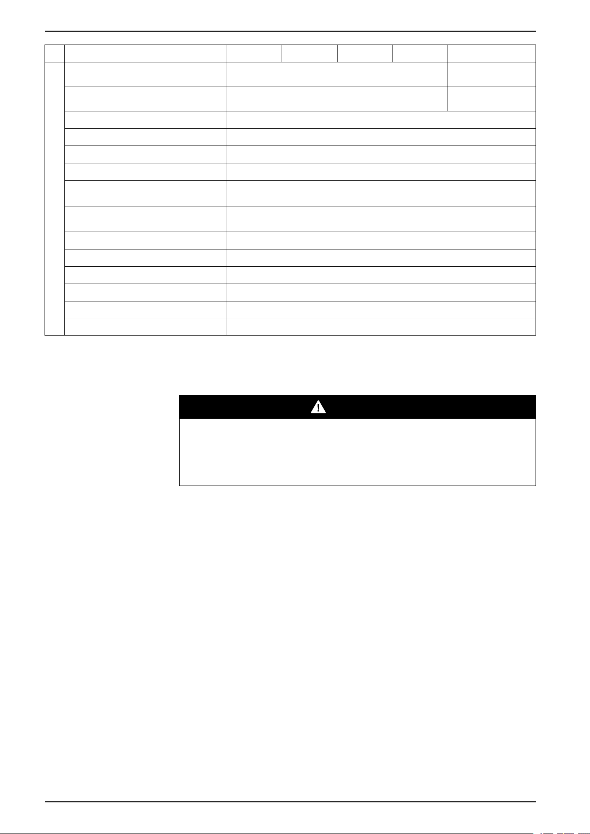
Voltage (V) 380 400 415 440 V 480 V
Charging power in % of output power 35% at ≤ 80% load, 12% at 100% load 40% at ≤ 80% load,
Maximum charging power (kW) 525 at < 80% load, 180 at 100% load, 600 at <80% load, 225
Nominal battery voltage (VDC) 480
Nominal float voltage (VDC) 546
End of discharge voltage (full load) (VDC) 384
End of discharge voltage (no load) (VDC) 420
Battery current at full load and nominal
battery voltage (A)
Battery current at full load and minimum
battery voltage (A)
Battery Specifications
Maximum battery backup time 1 hour
Temperature compensation (per cell) -3.3 mV per °C for T ≥ 25 °C, 0 mV per °C for T < 25 °C
Ripple current < 5% C20 (5 minutes backup time)
Battery test Manual/automatic (selectable)
Deep discharge protection Yes
Recharge according to battery temperature Yes
3269
4086
15% at 100% load
at 100% load
Recommended Upstream Protection and Cable Sizes – IEC
DANGER
HAZARD OF ELECTRIC SHOCK, EXPLOSION, OR ARC FLASH
An easily accessible breaker is required for upstream protection. Maximum fault
current disconnection time: 46 seconds at 200% input.
Failure to follow these instructions will result in death or serious injury.
NOTE: Overcurrent protection is to be provided by others.
Cable sizes in this manual are based on table B.52.12 and B.52.13 of IEC 60364–
5–52 with the following assertions:
• 90 °C conductors
• An ambient temperature of 30 °C
• Use of copper or aluminium conductors
• Installation method F4 for DC cables and installation method F5 for AC
cables, corrected for single layer in perforated cable tray.
PE cables are sized in accordance with IEC 60364-5-54 table 54.2 Minimum
cross-sectional area of protective conductors.
NOTE: Always consider the PE size according to the complete electrical
installation.
If the ambient temperature is greater than 30 °C, larger conductors are to be
selected in accordance with the correction factors of the IEC.
NOTE: The use of aluminium conductors can limit the number of parallel Li-ion
battery cabinets. Please contact Schneider Electric for more information.
42 990-5850F-001
Page 43
Facility Planning 380 V, 400 V, 415 V, and 440 V UPS System
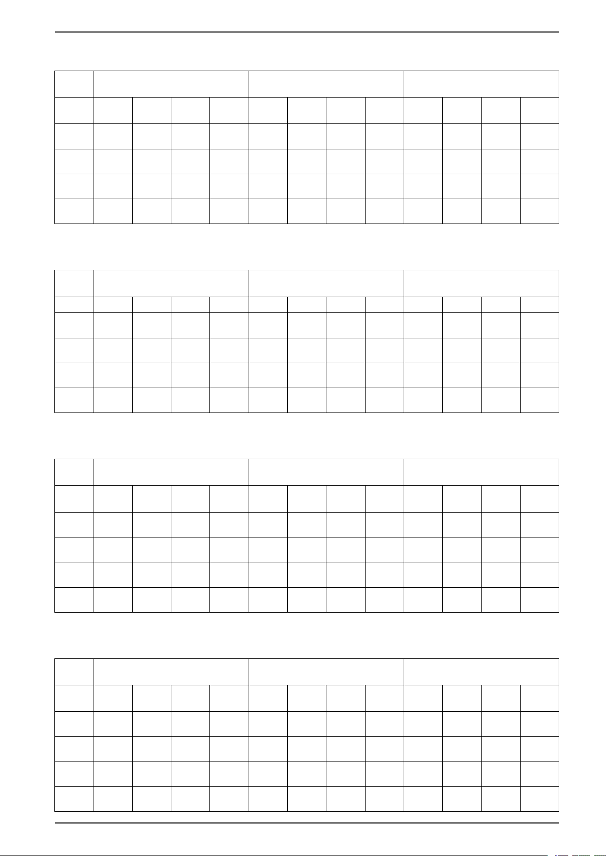
Recommended Upstream Protection and Cable Sizes for 500 kW UPS
Maximum OCPD (A) Conductors per Phase Copper/
PE Conductor (mm²)
Aluminium (mm²)
Voltage
380 400 415 440 380 400 415 440 380 400 415 440
(V)
Input 1000
I
=0.90
r
Bypass 800
I
=0.98
r
Output 800
=0.98
I
r
Battery 1500 1500 1500 1500 3x185/
1000
Ir=0.90
800
Ir=0.95
800
Ir=0.95
1000
Ir=0.90
800
Ir=0.9
800
Ir=0.9
1000
Ir=0.90
800
Ir=0.9
800
Ir=0.9
2x240/
3x185
2x185/
2x240
2x185/
2x240
3x240
2x240/
3x185
2x150/
2x240
2x150/
2x240
3x185/
3x240
2x240/
3x185
2x150/
2x240
2x150/
2x240
3x185/
3x240
2x240/
3x185
2x150/
2x240
2x150/
2x240
3x185/
3x240
1x240/
2x150
1x185/
1x240
1x185/
1x240
2x150/
2x185
Recommended Upstream Protection and Cable Sizes for 625 kW UPS
Maximum OCPD (A) Conductors per Phase Copper/
Aluminium (mm²)
380 V 400 V 415 V 440 V 380 V 400 V 415 V 440 V 380 V 400 V 415 V 440 V
Input 1250
I
=0.9
r
Bypass 1000
I
=0.98
r
Output 1000
=0.98
I
r
1250
Ir=0.9
1000
Ir=0.95
1000
Ir=0.95
1250
Ir=0.9
1000
Ir=0.9
1000
Ir=0.9
1250
Ir=0.9
1000
Ir=0.9
1000
Ir=0.9
3x185/
3x240
2x240/
3x240
2x240/
3x240
Battery 2000 2000 2000 2000 3x240/
4x240
3x185/
3x240
2x240/
3x185
2x240/
3x185
3x240/
4x240
3x185/
3x240
2x240/
3x185
2x240/
3x185
3x240/
4x240
3x185/
3x240
2x240/
3x185
2x240/
3x185
3x240/
4x240
PE Conductor (mm²)
2x150/
2x185
1x240/
2x185
1x240/
2x185
2x185/
2x240
1x240/
2x150
1x150/
1x240
1x150/
1x240
2x150/
2x185
2x150/
2x185
1x240/
2x150
1x240/
2x150
2x185/
2x240
1x240/
2x150
1x150/
1x240
1x150/
1x240
2x150/
2x185
2x150/
2x185
1x240/
2x150
1x240/
2x150
2x185/
2x240
1x240/
2x150
1x150/
1x240
1x150/
1x240
2x150/
2x185
2x150/
2x185
1x240/
2x150
1x240/
2x150
2x185/
2x240
Recommended Upstream Protection and Cable Sizes for 750 kW UPS
Maximum OCPD (A) Conductors per Phase Copper/
Aluminium (mm²)
Voltage
380 400 415 440 380 400 415 440 380 400 415 440
(V)
Input 1600
I
=0.9
r
Bypass 1250
I
=0.95
r
Output 1250
=0.95
I
r
1600
Ir=0.9
1250
Ir=0.9
1250
Ir=0.9
1600
Ir=0.9
1250
Ir=0.9
1250
Ir=0.9
1250
Ir=1.0
1000
Ir= 1.0
1000
Ir=1.0
3x240/
4x240
3x185/
4x185
3x185/
4x185
Battery 2500 2500 2500 2500 4x240/
5x240
3x240/
4x240
3x185/
3x240
3x185/
3x240
4x240/
5x240
3x240/
4x240
3x185/
3x240
3x185/
3x240
4x240/
5x240
3x185
4x240
2x240/
3x240
2x240/
3x240
4x240/
5x240
PE Conductor (mm²)
2x185/
2x240
2x150/
2x185
2x150/
2x185
2x240/
3x240
Recommended Upstream Protection and Cable Sizes for 800 kW UPS
Maximum OCPD (A) Conductors per Phase Copper/
Aluminium (mm²)
Voltage
380 400 415 440 380 400 415 440 380 400 415 440
(V)
Input 1600
I
=0.9
r
Bypass 1250
I
=1.0
r
Output 1250
I
=1.0
r
1600
Ir=0.9
1250
Ir=0.95
1250
Ir=0.95
1600
Ir=0.9
1250
Ir=0.9
1250
Ir=0.9
1600
Ir=0.9
1250
Ir=0.9
1250
Ir=0.9
3x240/
4x240
3x185/
4x240
3x185/
4x240
Battery 2500 2500 2500 2500 4x240/
5x240
3x240/
4x240
3x185/
4x185
3x185/
4x185
4x240/
5x240
3x240/
4x240
3x185/
3x240
3x185/
3x240
4x240/
5x240
3x240/
4x240
3x185/
3x240
3x185/
3x240
4x240/
5x240
PE Conductor (mm²)
2x185/
2x240
2x150/
2x185
2x150/
2x185
2x240/
3x240
2x185/
2x240
2x150/
2x185
2x150/
2x185
2x240/
3x240
2x185/
2x240
2x150/
2x185
2x150/
2x185
2x240/
3x240
2x185/
2x240
2x150/
2x185
2x150/
2x185
2x240/
3x240
2x185/
2x240
2x150/
2x185
2x150/
2x185
2x240/
3x240
2x150/
2x240
1x240/
2x185
1x240/
2x185
2x240/
3x240
2x185/
2x240
2x150/
2x185
2x150/
2x185
2x240/
3x240
990-5850F-001 43
Page 44
380 V, 400 V, 415 V, and 440 V UPS System Facility Planning
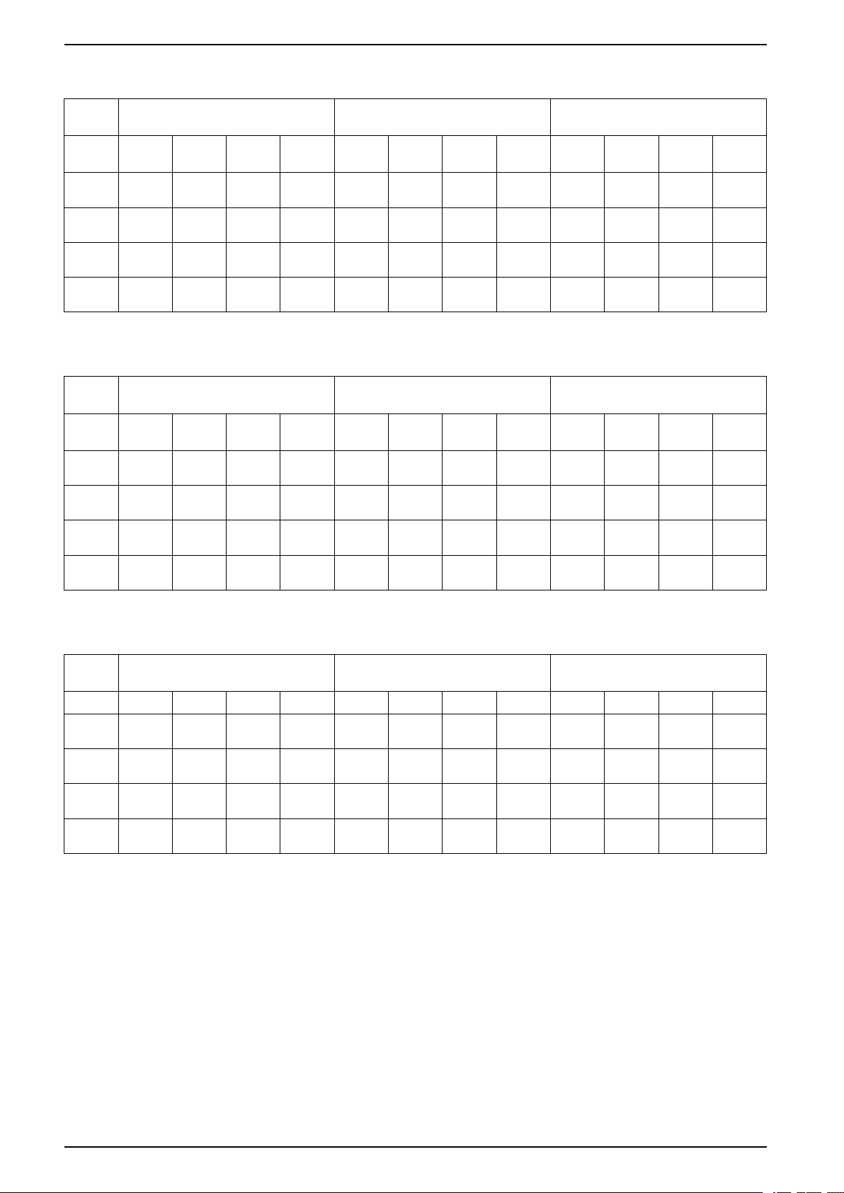
Recommended Upstream Protection and Cable Sizes for 1000 kW UPS
Maximum OCPD (A) Conductors per Phase Copper/
PE Conductor (mm²)
Aluminium (mm²)
Voltage
380 400 415 440 380 400 415 440 380 400 415 440
(V)
Input 2000
I
=0.9
r
Bypass 1600
I
=0.98
r
Output 1600
=0.98
I
r
Battery 3300 3300 3300 3300 5x240/
2000
Ir=0.9
1600
Ir=0.95
1600
Ir=0.98
2000
Ir=0.9
1600
Ir=0.9
1600
Ir=0.9
2000
Ir=0.9
1600
Ir=0.9
1600
Ir=0.9
4x240/
6x240
4x185/
5x240
4x240/
6x240
7x240
4x240/
6x240
4x185/
5x240
4x240/
6x240
5x240/
7x240
4x240/
6x240
3x240/
4x240
3x240/
6x240
5x240/
7x240
4x240/
6x240
3x240/
4x240
3x240/
6x240
5x240/
7x240
2x240/
3x240
2x185/
3x240
2x240/
3x240
3x240/
4x240
2x240/
3x240
2x185/
3x240
2x240/
3x240
3x240/
4x240
Recommended Upstream Protection and Cable Sizes for 1100 kW UPS
Maximum OCPD (A) Conductors per Phase Copper/
Aluminium (mm²)
Voltage
380 400 415 440 380 400 415 440 380 400 415 440
(V)
Input 2000
I
=0.98
r
Bypass 2000
I
=0.9
r
Output 2000
=0.9
I
r
2000
Ir=0.98
2000
Ir=0.9
2000
Ir=0.9
2000
Ir=0.98
1600
Ir=0.98
1600
Ir=0.98
2000
Ir=0.95
1600
Ir=0.95
1600
Ir=0.95
4x300/
5x300
4x240/
5x300
4x240/
5x300
Battery 3300 3300 3300 3300 5x300/
7x300
4x300/
5x300
4x240/
5x300
4x240/
5x300
5x300/
7x300
4x300/
5x300
3x300/
4x300
3x300/
4x300
5x300/
7x300
4x300/
5x300
3x300/
4x300
3x300/
4x300
5x300/
7x300
PE Conductor (mm²)
2x300/
3x300
2x240/
3x300
2x240/
3x300
3x300/
4x300
2x300/
3x300
2x240/
3x300
2x240/
3x300
3x300/
4x300
2x240/
3x240
2x185/
2x240
2x240/
3x240
3x240/
4x240
2x300/
3x300
2x240
2x300
2x240
2x300
3x300/
4x300
2x240/
3x240
2x185/
2x240
2x240/
3x240
3x240/
4x240
2x300/
3x300
2x240/
2x300
2x240/
2x300
3x300/
4x300
Recommended Upstream Protection and Cable Sizes for 1250 kW UPS
Maximum OCPD (A) Conductors per Phase Copper/
Aluminium (mm²)
380 V 400 V 415 V 440 V 380 V 400 V 415 V 440 V 380 V 400 V 415 V 440 V
Input 2500
I
=0.9
r
Bypass 2000
I
=0.98
r
Output 2000
=0.98
I
r
2500
Ir=0.9
2000
Ir=0.95
2000
Ir=0.95
2500
Ir=0.9
2000
Ir=0.9
2000
Ir=0.9
2500
Ir=0.9
2000
Ir=0.9
2000
Ir=0.9
5x240/
6x300
4x300/
5x300
4x300/
5x300
Battery 4000 4000 4000 4000 6x300/
7x300
5x240/
6x300
4x300/
5x300
4x300/
5x300
6x300/
7x300
5x240/
6x300
4x240/
5x300
4x240/
5x300
6x300/
7x300
5x240/
6x300
4x240/
5x300
4x240/
5x300
6x300/
7x300
PE Conductor (mm²)
3x240/
3x300
2x300/
3x300
2x300/
3x300
3x300/
4x300
3x240/
3x300
2x300/
3x300
2x300/
3x300
3x300/
4x300
3x240/
3x300
2x240/
3x300
2x240/
3x300
3x300/
4x300
3x240/
3x300
2x240/
3x300
2x240/
3x300
3x300/
4x300
44 990-5850F-001
Page 45

Facility Planning 380 V, 400 V, 415 V, and 440 V UPS System
Recommended Upstream Protection and Cable Sizes for 1500 kW UPS
Maximum OCPD (A) Conductors per Phase Copper/
PE Conductor (mm²)
Aluminium (mm²)
380 V 400 V 415 V 440 V 380 V 400 V 415 V 440 V 380 V 400 V 415 V 440 V
Input 3200
Bypass 2500
Output 2500
61
63
63
Battery 4000 4000 4000 4000 8x240/
3200
2500
2500
61
61
61
3200
2500
2500
61
61
61
2500
2000
2000
62
7x240/
9x240
62
6x240/
7x240
62
6x240/
7x240
10x240
7x240/
9x240
5x240/
7x240
5x240/
7x240
8x240/
10x240
7x240/
9x240
5x240/
7x240
5x240/
7x240
8x240/
10x240
6x240/
8x240
5x240/
6x240
5x240/
6x240
8x240/
10x240
4x240/
5x240
3x240/
4x240
3x240/
4x240
4x240/
5x240
4x240/
5x240
3x240/
4x240
3x240/
4x240
4x240/
5x240
4x240/
5x240
3x240/
4x240
3x240/
4x240
4x240/
5x240
Weights and Dimensions
Weights and Dimensions for UPSs with 1250 kW I/O Cabinet
Commercial Reference Parts Weight kg Height mm Width mm Depth mm
• GVX500K500NHS
• GVX500K750NHS
• GVX500K1000NHS
• GVX500K1250NHS
• GVX625K625NHS
• GVX625K1000NHS
• GVX750K500NHS
• GVX750K750NHS
• GVX750K1000NHS
• GVX750K1250NHS
• GVX800K800NHS
• GVX1000K750NHS
• GVX1000K1000NHS
• GVX1000K1250NHS
• GVX1100K1100NHS
• GVX1250K1000NHS
• GVX1250K1250NHS
• GVX1500K1100NHS
• GVX1500K1250NHS
Total
– Power cabinets
– I/O cabinet
Total
– Power cabinets
– I/O cabinet
Total
– Power cabinets
– I/O cabinet
Total
– Power cabinets
– I/O cabinet
Total
– Power cabinets
– I/O cabinet
2030 (4475)
2x540 (2x1190)
950 (2094)
2570 (5666)
3x540 (3x1190)
950 (2094)
3110 (6856)
4x540 (4x1190)
950 (2094)
3650 (8047)
5x540 (5x1190)
950 (2094)
4190 (9237)
6x540 (6x1190)
950 (2094)
1970 (77.6) 2400 (94.5)
2x600 (2x23.6)
1200 (47.2)
1970 (77.6) 3000 (118.1)
3x600 (3x23.6)
1200 (47.2)
1970 (77.6) 3600 (141.7)
4x600 (4x23.6)
1200 (47.2)
1970 (77.6) 4200 (165.4)
5x600 (5x23.6)
1200 (47.2)
1970 (77.6) 4800 (189.0)
6x600 (6x23.6)
1200 (47.2)
900 (35.4)
900 (35.4)
900 (35.4)
900 (35.4)
900 (35.4)
3x240/
4x240
3x240/
3x240
3x240/
3x240
4x240/
5x240
61. Long-time setting (Ir) = 0.9.
62. Long-time setting (I
63. Long-time setting (I
) = 1.0.
r
) = 0.95.
r
990-5850F-001 45
Page 46
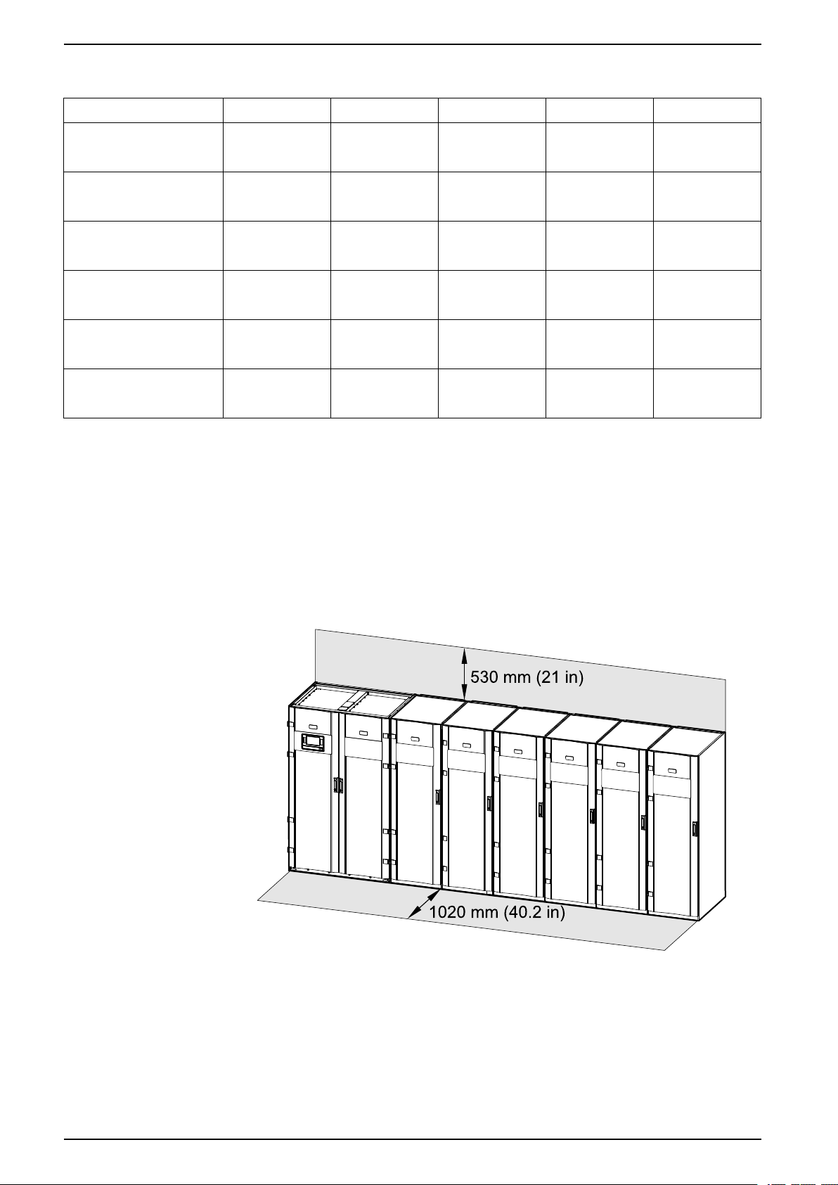
380 V, 400 V, 415 V, and 440 V UPS System Facility Planning
Weights and Dimensions for UPSs with 1500 kW I/O Cabinet
Part Number Parts Weight kg (lbs) Height mm (in) Width mm (in) Depth mm (in)
• GVX500K1500HS
• GVX750K1500HS
• GVX1000K1500HS
• GVX1250K1500HS
• GVX1500K1500HS
• GVX1750K1500HS
In total
– Power cabinets
– I/O cabinet
In total
– Power cabinets
– I/O cabinet
In total
– Power cabinets
– I/O cabinet
In total
– Power cabinets
– I/O cabinet
In total
– Power cabinets
– I/O cabinet
In total
– Power cabinets
– I/O cabinet
1956 (4312)
2x540 (2x1190)
876 (1931)
2496 (5503)
3x540 (3x1190)
876 (1931)
3036 (6693)
4x540 (4x1190)
876 (1931)
3576 (7884)
5x540 (5x1190)
876 (1931)
4116 (9074)
6x540 (6x1190)
876 (1931)
4656 (10265)
7x540 (7x1190)
876 (1931)
Clearance
Clearance for UPSs with 1250 kW I/O Cabinet
1970 (77.6) 3200 (126.0)
2x600 (2x23.6)
2000 (78.7)
1970 (77.6) 3800 (149.6)
3x600 (3x23.6)
2000 (78.7)
1970 (77.6) 4400 (173.2)
4x600 (4x23.6)
2000 (78.7)
1970 (77.6) 5000 (196.9)
5x600 (5x23.6)
2000 (78.7)
1970 (77.6) 5600 (220.5)
6x600 (6x23.6)
2000 (78.7)
1970 (77.6) 6200 (244.1)
7x600 (7x23.6)
2000 (78.7)
900 (35.4)
900 (35.4)
900 (35.4)
900 (35.4)
900 (35.4)
900 (35.4)
NOTE: Clearance dimensions are published for airflow and service access
only. Consult with the local safety codes and standards for additional
requirements in your local area.
NOTE: The UPS system can be placed up against a wall and there is no
requirement for rear or side access.
Clearance for UPSs with 1500 kW I/O Cabinet
NOTE: Clearance dimensions are published for airflow and service access
only. Consult with the local safety codes and standards for additional
requirements in your local area.
NOTE: The UPS system can be placed up against a wall with no requirement
for rear or side access.
46 990-5850F-001
Page 47
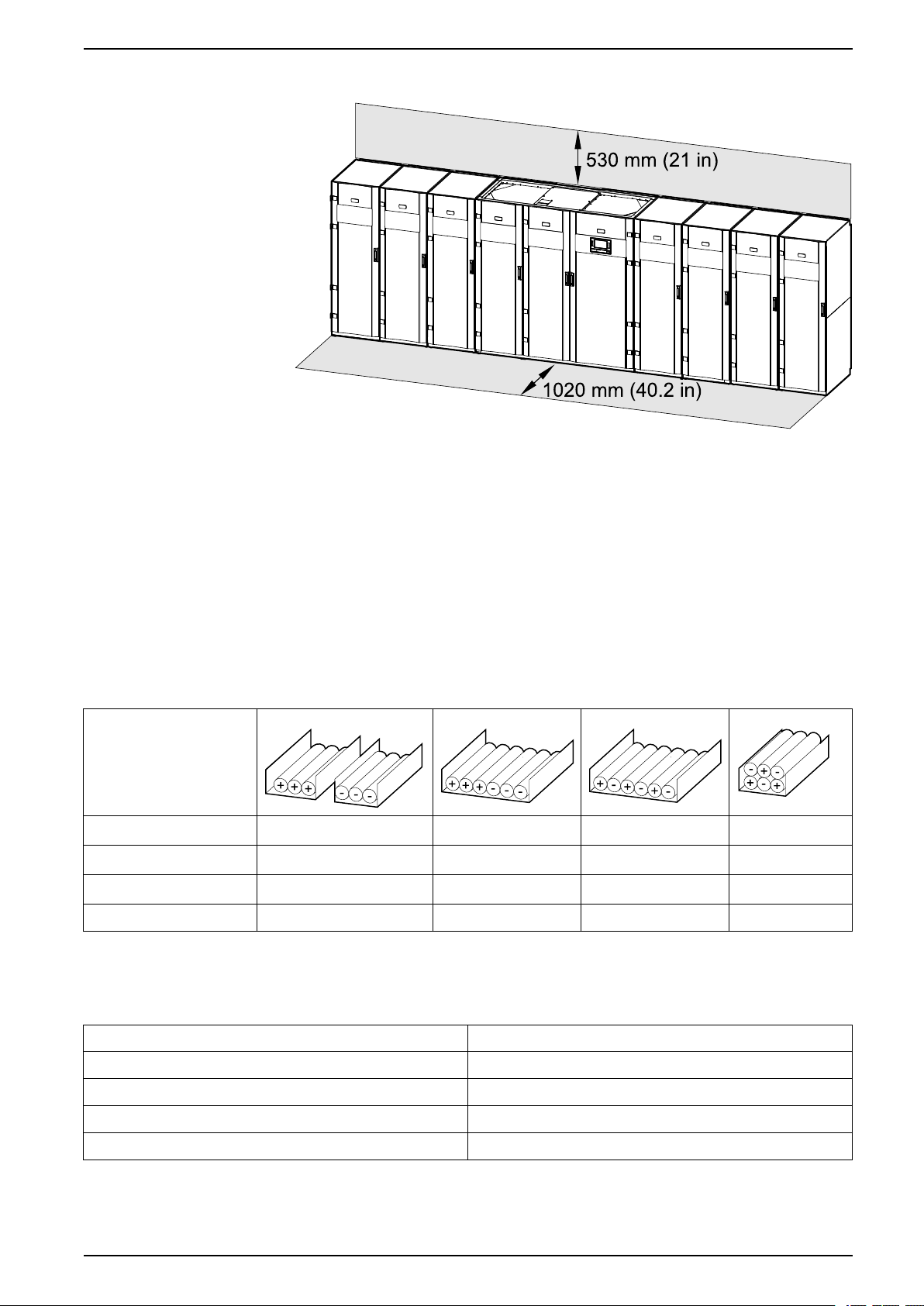
Facility Planning 380 V, 400 V, 415 V, and 440 V UPS System
Front View
Guidance for Organizing Battery Cables
NOTE: For 3rd party batteries, use only high rate batteries for UPS
applications.
NOTE: When the battery bank is placed remotely, the organizing of the cables
is important to reduce voltage drop and inductance. The distance between the
battery bank and the UPS must not exceed 200 m (656 ft). Contact Schneider
Electric for installations with a longer distance.
NOTE: To minimize the risk of electromagnetic radiation, it is highly
recommended to follow the below guidance and to use grounded metallic tray
supports.
Cable Length
<30 m Not recommended
31–75 m Not recommended Not recommended
76–150 m Not recommended Not recommended
151–200 m Not recommended Not recommended Not recommended Recommended
Acceptable Recommended Recommended
Acceptable Recommended
Acceptable Recommended
Torque Specifications
Bolt size Torque
M6 5 Nm (3.69 lb-ft)
M8 17.5 Nm (12.91 lb-ft)
M10 30 Nm (22 lb-ft)
M12 50 Nm (36.87 lb-ft)
990-5850F-001 47
Page 48
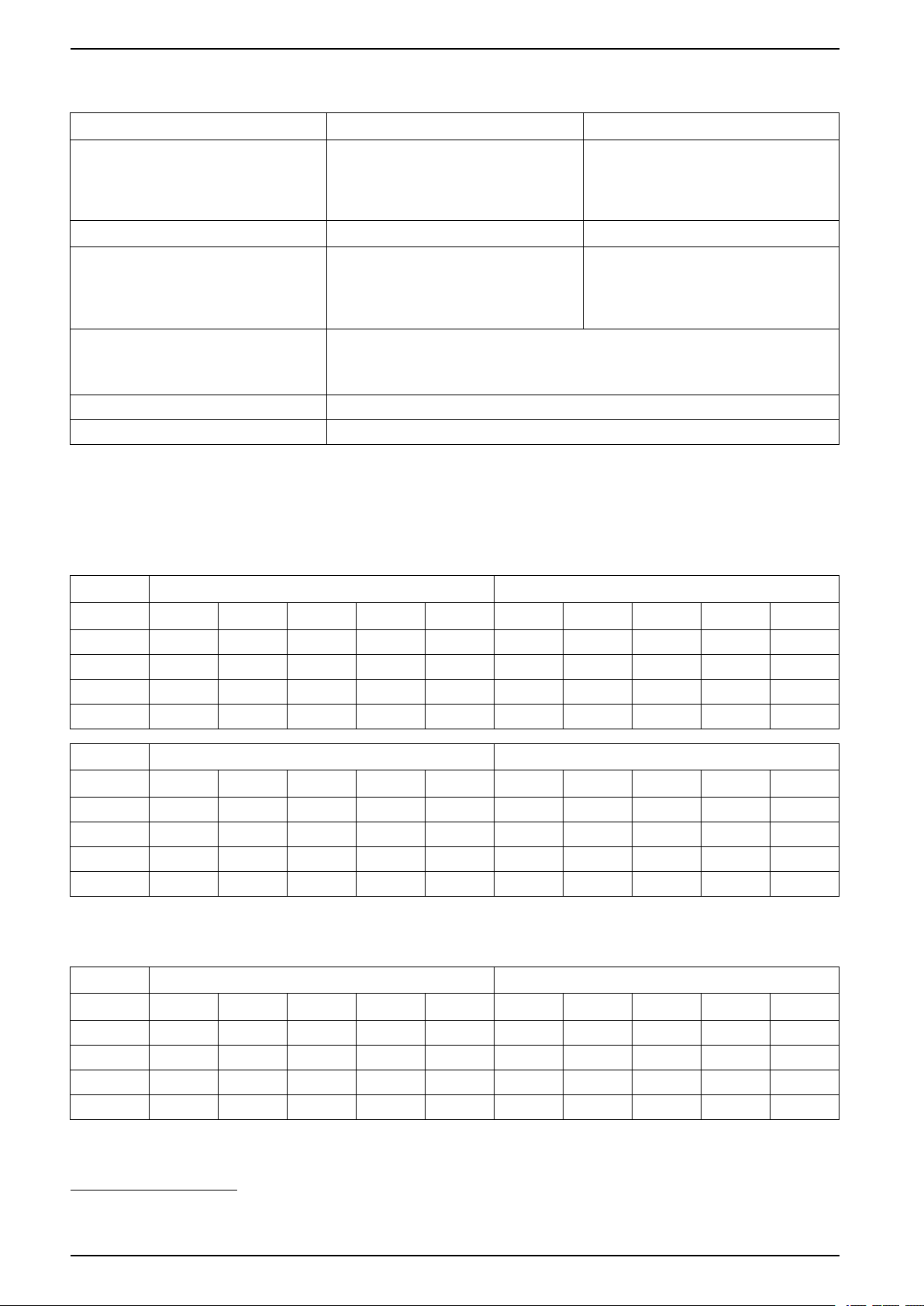
380 V, 400 V, 415 V, and 440 V UPS System Facility Planning
Environment
Operating Storage
Temperature 0 °C to 40 °C ( 32 °F to 104 °F )
0 °C to 50 °C ( 32 °F to 122 °F ) when
derated to 75% power
Relative humidity 0 – 95% non-condensing 0 – 95% non-condensing
Altitude derating according to ANSI C57.96–
65
1999
Audible noise one meter (three feet) from
surface
Protection class IP20
Color RAL 9003 white
1000 m (3300 ft): 1.000
1500 m (5000 ft): 0.975
2000 m (6600 ft): 0.950
2500 m (8300 ft): 0.925
3000 m (10000 ft): 0.900
62 dB at 70% load
69.5 dB at 100% load for 400 V systems
68 dB at 100% load for 480 V systems
64
-15 °C to 40 °C (5 °F to 104 °F) for systems
with batteries
-25 °C to 55 °C (-13 °F to 131 °F) for
systems without batteries
0 – 15000 m (0 – 50000 ft)
Heat Dissipation (BTU/hr) for UPSs with 1250 kW I/O Cabinet
Heat Dissipation for 500 kW UPS
Normal operation
Voltage (V) 380 400 415 440 V 480 V 380 400 415 440 V 480 V
ECO mode
25% load 17771 21504 21504 21504 22920 11385 16847 16387 14099 11835
50% load 34617 38327 38327 37397 36468 8616 11235 10360 12112 13870
75% load 56095 58889 58889 56095 53313 12924 15540 15540 15540 15540
100% load 78519 80387 78519 75723 72936 13758 17232 17232 17232 17232
ECOnversion
Voltage (V) 380 400 415 440 V 480 V 380 400 415 440 V 480 V
25% load 4308 7376 6935 10264 13644 14555 15469 15011 15011 15011
50% load 13870 12990 16521 16078 15635 29110 29110 30938 30938 29110
75% load 12924 14231 14231 15540 16853 75903 47782 49160 49160 49160
100% load 17232 13758 13758 16362 18975 71083 74793 80387 80387 72936
Battery operation
Heat Dissipation for 625 kW UPS
Normal operation
Voltage (V) 380 400 415 440 V 480 V 380 400 415 440 V 480 V
25% load 27469 26880 26880 26880 28059 10880 13110 13670 13670 13670
50% load 47909 47909 47909 45006 42118 11859 14044 15139 15139 15139
75% load 73611 73611 73611 67509 61451 16155 19426 19426 19426 19426
100% load 114602 100484 98149 91170 84236 23718 25901 25901 23718 21540
ECO mode
64. For temperatures between 40 °C and 50 °C, the load power rating must be derated with 2.5% per °C of rated output power. Above 40 °C
the minimum input voltage is 340 V, and from 380 V to 340 V, the charge power must be linearly derated from 12% to 1%.
65. Maximum operation altitude is 3000 m (10000 ft).
48 990-5850F-001
Page 49
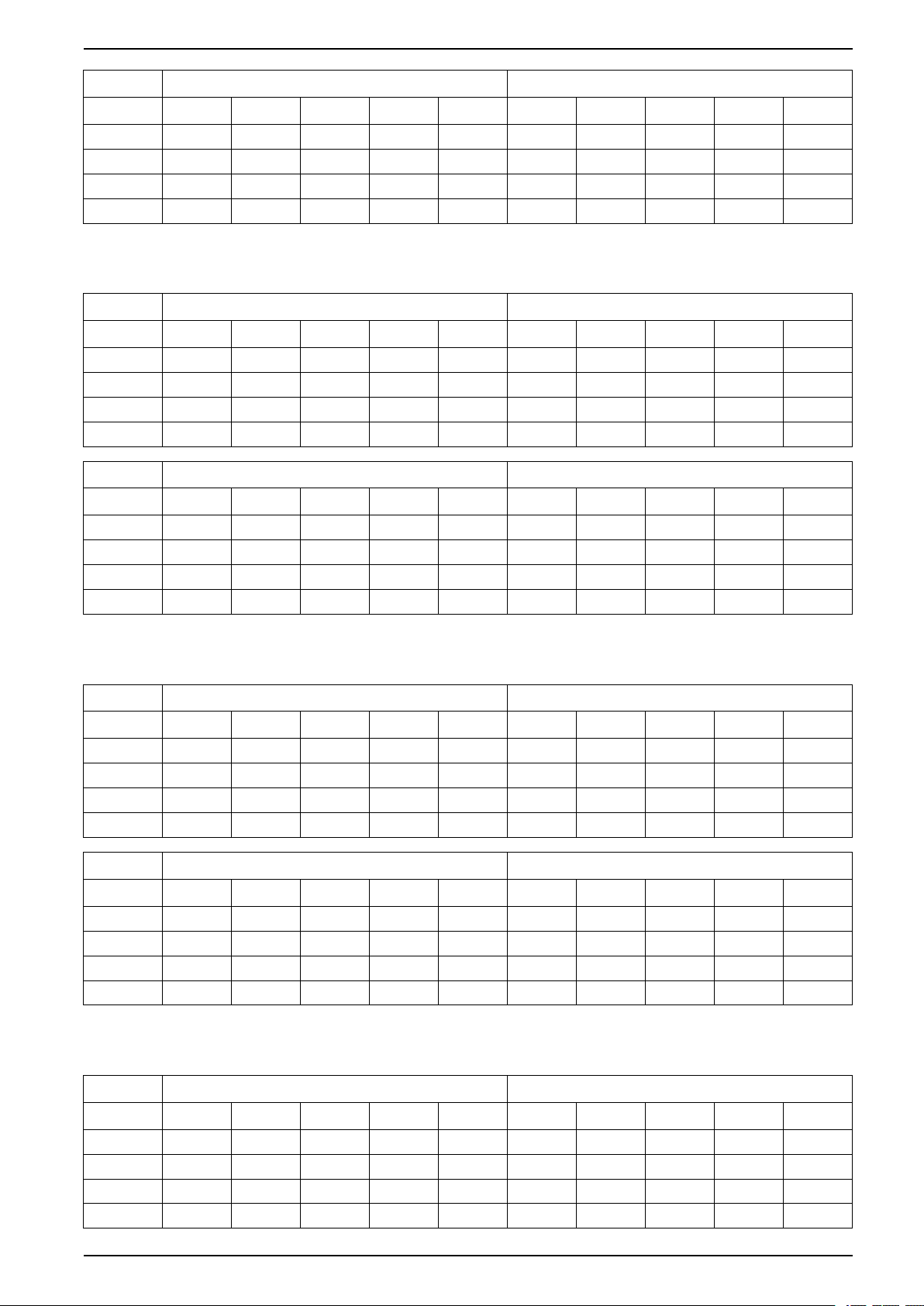
Facility Planning 380 V, 400 V, 415 V, and 440 V UPS System
ECOnversion
Voltage (V) 380 400 415 440 V 480 V 380 400 415 440 V 480 V
25% load 15922 15922 10880 13390 15922 17056 17056 18764 18764 18764
50% load 17337 17337 17337 17337 17337 40967 39818 38672 38672 36387
75% load 21066 21066 21066 21066 21066 61451 61451 61451 61451 61451
100% load 25901 25901 25901 24809 23718 86543 84236 100484 100484 91170
Battery operation
Heat Dissipation for 750 kW UPS
Normal operation
Voltage (V) 380 400 415 440 V 480 V 380 400 415 440 V 480 V
25% load 28745 30847 30847 30847 30847 10402 13056 13723 13723 13723
50% load 56095 56095 54702 53313 51926 14231 16853 18167 18167 18167
75% load 94653 92542 86236 83097 79969 19386 23311 23311 23311 23311
100% load 146074 137523 129025 120581 112190 25848 28462 28462 28462 28462
ECOnversion
Voltage (V) 380 400 415 440 V 480 V 380 400 415 440 V 480 V
25% load 15061 15061 9084 12058 15061 21832 21832 22517 22517 23203
50% load 19485 19485 19485 19485 19485 45034 43664 45034 45034 45034
75% load 25279 25279 25279 25279 25279 77888 75812 75812 75812 75812
100% load 31081 31081 31081 29771 28462 114981 112190 112190 112190 112190
ECO mode
Battery operation
Heat Dissipation for 800 kW UPS
Normal operation
Voltage (V) 380 400 415 440 V 480 V 380 400 415 440 V 480 V
25% load 35160 35160 34407 34407 34407 15351 15351 8988 8988 8988
50% load 59835 58349 56867 55387 53911 19378 19378 15180 15180 15180
75% load 91985 89752 85300 84190 83081 22770 22770 22770 22770 22770
100% load 131616 128620 119669 112253 104876 30360 27572 27572 27572 27572
ECOnversion
Voltage (V) 380 400 415 440 V 480 V 380 400 415 440 V 480 V
25% load 17497 18216 17497 17857 18216 26956 21831 21105 21105 7590
50% load 20784 20784 20784 20784 20784 50968 43662 48036 48036 48036
75% load 24865 24865 24865 24865 24865 78657 65493 67676 67676 67676
100% load 30360 30360 27572 26180 24790 113733 101935 104876 104876 104876
ECO mode
Battery operation
Heat Dissipation for 1000 kW UPS
Normal operation
Voltage (V) 380 400 415 440 V 480 V 380 400 415 440 V 480 V
ECO mode
25% load 36468 39259 39259 39259 39259 12112 15635 16521 16521 16521
50% load 71083 71083 69234 69234 65547 15493 18975 20721 20721 20721
75% load 120581 117778 109405 109405 101083 20637 25848 25848 25848 25848
100% load 187156 175802 164520 164520 142167 27516 30987 30987 30987 30987
990-5850F-001 49
Page 50
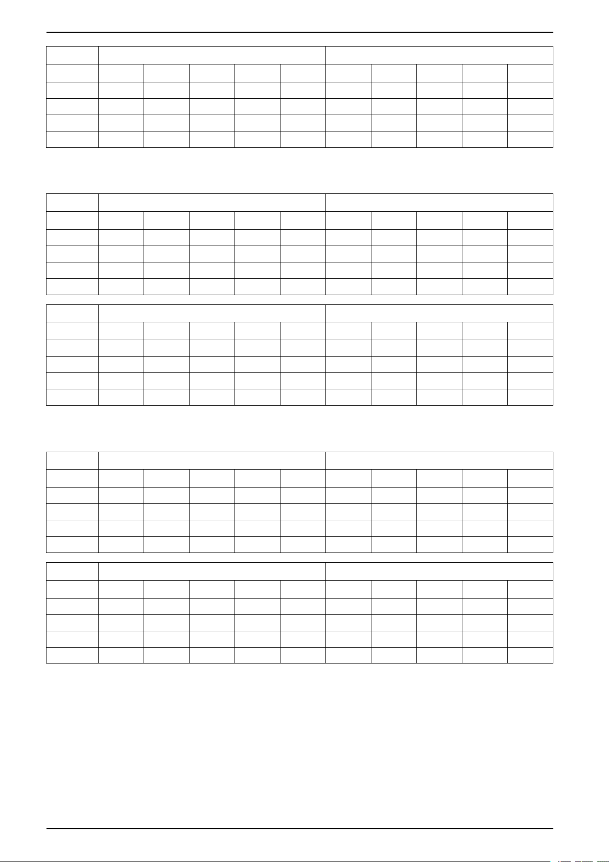
380 V, 400 V, 415 V, and 440 V UPS System Facility Planning
ECOnversion
Voltage (V) 380 400 415 440 V 480 V 380 400 415 440 V 480 V
25% load 18297 18297 10360 14311 18297 28198 28198 29110 29110 30023
50% load 22470 22470 22470 22470 22470 58219 56397 58219 58219 58219
75% load 28462 28462 28462 28462 28462 101083 98321 98321 98321 98321
100% load 34465 34465 34465 32725 30987 149587 145873 145873 145873 145873
Battery operation
Heat Dissipation for 1100 kW UPS
Normal operation
Voltage (V) 380 400 415 440 V 480 V 380 400 415 440 V 480 V
25% load 43185 43185 42160 43185 41136 18173 17199 17199 16713 16227
50% load 82273 78192 76158 76158 70080 22793 22793 22793 21832 20872
75% load 132639 123409 120345 120345 108153 28433 25564 25564 26998 28433
100% load 201700 185100 180972 180972 152315 37911 37911 37911 35997 34086
ECOnversion
Voltage (V) 380 400 415 440 V 480 V 380 400 415 440 V 480 V
25% load 21107 21107 20127 18173 21107 35040 37064 36051 32021 36051
50% load 24717 22793 24717 22793 24717 66050 66050 70080 64041 68063
75% load 34189 34189 34189 28433 31308 163830 102095 105121 108153 105121
100% load 53291 41744 41744 34086 37911 156383 164545 176852 160460 152315
ECO mode
Battery operation
Heat Dissipation for 1250 kW UPS
Normal operation
Voltage (V) 380 400 415 440 V 480 V 380 400 415 440 V 480 V
25% load 49074 49074 47909 47909 46746 20651 19544 19544 18992 18440
50% load 93492 88854 86543 83084 79637 25901 25901 25901 24809 23718
75% load 154237 143726 140237 133281 126354 35578 32311 32311 30680 29050
100% load 233945 215042 210341 193965 177708 43081 43081 43081 40906 38734
ECOnversion
Voltage (V) 380 400 415 440 V 480 V 380 400 415 440 V 480 V
25% load 22872 22872 21760 22316 22872 36387 38672 37528 37528 37528
50% load 28088 25901 28088 28088 28088 72774 72774 77345 77345 75057
75% load 35578 35578 35578 33943 32311 119455 119455 122901 122901 122901
100% load 56175 43081 43081 40906 38734 177708 186983 200969 200969 173085
ECO mode
Battery operation
50 990-5850F-001
Page 51
Facility Planning 380 V, 400 V, 415 V, and 440 V UPS System
Heat Dissipation (BTU/hr) for UPSs with 1500 kW I/O Cabinet
Heat Dissipation for 500 kW UPS
Normal operation
Voltage (V) 380 400 415 440 V 480 V 380 400 415 440 V 480 V
25% load 17309 16387 16387 16387 18698 5618 5618 5618 6056 6495
50% load 32774 30938 30938 31396 31855 7747 7747 7747 7747 7747
75% load 53313 50542 50542 50542 50542 11620 11620 11620 10969 10319
100% load 86017 82260 82260 75723 69234 13758 13758 13758 13758 13758
ECOnversion
Voltage (V) 380 400 415 440 V 480 V 380 400 415 440 V 480 V
25% load 6495 6495 6495 7155 7818 18234 18234 18234 18234 18234
50% load 7747 7747 7747 7747 7747 31855 31855 31855 31855 31855
75% load 11620 11620 11620 10969 10319 53313 53313 53313 53313 53313
100% load 15493 13758 13758 13758 13758 78519 78519 78519 78519 78519
ECO mode
Battery operation
Heat Dissipation for 750 kW UPS
Normal operation
Voltage (V) 380 400 415 440 V 480 V 380 400 415 440 V 480 V
25% load 26656 25271 25271 25271 27351 9084 9084 9084 9413 9742
50% load 51926 49160 49160 47782 46407 12924 12924 12924 12272 11620
75% load 86236 82053 82053 77888 73741 17430 17430 17430 16453 15478
100% load 134684 129025 129025 117778 106625 23240 23240 23240 21938 20637
ECO mode
ECOnversion
Voltage (V) 380 400 415 440 V 480 V 380 400 415 440 V 480 V
25% load 9742 9742 9742 10733 11727 27351 27351 27351 27351 27351
50% load 12924 12924 12924 12924 12924 47782 47782 47782 47782 47782
75% load 17430 17430 17430 16453 15478 79969 79969 79969 79969 79969
100% load 23240 23240 23240 21938 20637 117778 117778 117778 117778 117778
Battery operation
Heat Dissipation for 1000 kW UPS
Normal operation
Voltage (V) 380 400 415 440 V 480 V 380 400 415 440 V 480 V
25% load 36468 34617 34617 33888 36468 12112 12112 12112 12112 12112
50% load 71083 67389 67389 60137 61876 17232 17232 17232 16362 15493
75% load 123390 117778 117778 98514 95564 23240 23240 23240 21938 20637
100% load 187156 179579 179579 149141 145873 30987 30987 30987 29251 27516
ECO mode
990-5850F-001 51
Page 52
380 V, 400 V, 415 V, and 440 V UPS System Facility Planning
ECOnversion
Voltage (V) 380 400 415 440 V 480 V 380 400 415 440 V 480 V
25% load 13334 13334 13334 14313 15294 36468 35819 36468 36468 36468
50% load 17254 17254 17254 16956 16657 63710 62976 63710 63710 63710
75% load 24358 24358 24358 22496 20637 106625 104128 106625 106625 106625
100% load 31342 31342 31342 29428 27516 157038 156664 157038 157038 157038
Battery operation
Heat Dissipation for 1250 kW UPS
Normal operation
Voltage (V) 380 400 415 440 V 480 V 380 400 415 440 V 480 V
25% load 44427 42118 42118 42118 44427 12950 12950 12950 13497 14044
50% load 86543 81934 81934 78490 75057 19367 19367 19367 18282 17198
75% load 147223 140237 140237 129814 119455 25796 25796 25796 24172 22549
100% load 224474 215042 215042 196297 177708 30065 30065 30065 30065 30065
ECOnversion
Voltage (V) 380 400 415 440 V 480 V 380 400 415 440 V 480 V
25% load 15569 15569 15569 17156 18748 45585 45585 45585 45585 45585
50% load 19394 19394 19394 19721 20047 79637 79637 79637 79637 79637
75% load 27191 27191 27191 25681 24172 133281 133281 133281 133281 133281
100% load 34838 34838 34838 32451 30065 196297 196297 196297 196297 196297
ECO mode
Battery operation
Heat Dissipation for 1500 kW UPS
Normal operation
Voltage
(V)
25% load 53313 50542 50542 50680 53313 15540 15540 15540 16131 16853
50% load 103851 98321 98321 91275 92813 23240 23240 23240 21626 23240
75% load 176667 168285 168285 151832 147481 30956 30956 30956 28889 27059
100%
load
Voltage
(V)
25% load 18683 18683 18683 17234 22054 54702 51372 54702 54702 54285
50% load 23273 23273 23273 20325 23129 95564 95014 95564 95564 96666
75% load 32629 32629 32629 26436 27059 159938 159521 159938 159938 154530
100%
load
380 400 415 440 V 480 V 380 400 415 440 V 480 V
269368 258050 258050 234549 213250 36079 36079 36079 37428 36079
ECOnversion
380 400 415 440 V 480 V 380 400 415 440 V 480 V
41806 41806 41806 35819 36079 235556 236677 235556 235556 229962
ECO mode
Battery operation
52 990-5850F-001
Page 53

Options 380 V, 400 V, 415 V, and 440 V UPS System
Options
Hardware Options
• Standard top cable entry battery cabinets or custom front terminal battery
cabinets
• Optional remote 10–inch LCD
• Optional Modbus RS-485 card
Configuration Options
• Single or dual feed
• Default top or bottom cable entry
• N+1 redundancy
• Up to 4+1 UPSs in parallel
• ECO mode
• ECOnversion mode
• StruxureWare Data Center Expert compatible
• Generator compatible
• Internal synchronization to alternate source (single system)
• Seismic rated brackets included
• Touchscreen LCD
990-5850F-001 53
Page 54

380 V, 400 V, 415 V, and 440 V UPS System Limited Factory Warranty
Limited Factory Warranty
One-Year Factory Warranty
The limited warranty provided by Schneider Electric in this Statement of Limited
Factory Warranty applies only to products you purchase for your commercial or
industrial use in the ordinary course of your business.
Terms of Warranty
Schneider Electric warrants that the product shall be free from defects in materials
and workmanship for a period of one year from the date of product start-up when
start-up is performed by Schneider Electric-authorized service personnel and
occurs within six months of the Schneider Electric shipment date. This warranty
covers repairing or replacing any defective parts including on-site labor and travel.
In the event that the product fails to meet the foregoing warranty criteria, the
warranty covers repairing or replacing defective parts at the sole discretion of
Schneider Electric for a period of one year from the shipment date. For Schneider
Electric cooling solutions, this warranty does not cover circuit breaker resetting,
loss of refrigerant, consumables, or preventive maintenance items. Repair or
replacement of a defective product or part thereof does not extend the original
warranty period. Any parts furnished under this warranty may be new or factoryremanufactured.
Non-transferable Warranty
This warranty is extended to the first person, firm, association or corporation
(herein referred to by “You” or “Your”) for whom the Schneider Electric product
specified herein has been purchased. This warranty is not transferable or
assignable without the prior written permission of Schneider Electric.
Assignment of Warranties
Schneider Electric will assign you any warranties which are made by
manufacturers and suppliers of components of the Schneider Electric product and
which are assignable. Any such warranties are assigned “AS IS” and Schneider
Electric makes no representation as to the effectiveness or extent of such
warranties, assumes no responsibility for any matters which may be warranted by
such manufacturers or suppliers and extends no coverage under this Warranty to
such components.
Drawings, Descriptions
Schneider Electric warrants for the warranty period and on the terms of the
warranty set forth herein that the Schneider Electric product will substantially
conform to the descriptions contained in the Schneider Electric Official Published
Specifications or any of the drawings certified and agreed to by contract with
Schneider Electric if applicable thereto (“Specifications”). It is understood that the
Specifications are not warranties of performance and not warranties of fitness for
a particular purpose.
54 990-5850F-001
Page 55

Limited Factory Warranty 380 V, 400 V, 415 V, and 440 V UPS System
Exclusions
Schneider Electric shall not be liable under the warranty if its testing and
examination disclose that the alleged defect in the product does not exist or was
caused by end user or any third person misuse, negligence, improper installation
or testing. Further, Schneider Electric shall not be liable under the warranty for
unauthorized attempts to repair or modify wrong or inadequate electrical voltage
or connection, inappropriate on-site operation conditions, corrosive atmosphere,
repair, installation, start-up by non-Schneider Electric designated personnel, a
change in location or operating use, exposure to the elements, Acts of God, fire,
theft, or installation contrary to Schneider Electric recommendations or
specifications or in any event if the Schneider Electric serial number has been
altered, defaced, or removed, or any other cause beyond the range of the
intended use.
THERE ARE NO WARRANTIES, EXPRESS OR IMPLIED, BY OPERATION OF
LAW OR OTHERWISE, OF PRODUCTS SOLD, SERVICED OR FURNISHED
UNDER THIS AGREEMENT OR IN CONNECTION HEREWITH. SCHNEIDER
ELECTRIC DISCLAIMS ALL IMPLIED WARRANTIES OF MERCHANTABILITY,
SATISFACTION AND FITNESS FOR A PARTICULAR PURPOSE. SCHNEIDER
ELECTRIC EXPRESS WARRANTIES WILL NOT BE ENLARGED, DIMINISHED,
OR AFFECTED BY AND NO OBLIGATION OR LIABILITY WILL ARISE OUT OF,
SCHNEIDER ELECTRIC RENDERING OF TECHNICAL OR OTHER ADVICE OR
SERVICE IN CONNECTION WITH THE PRODUCTS. THE FOREGOING
WARRANTIES AND REMEDIES ARE EXCLUSIVE AND IN LIEU OF ALL OTHER
WARRANTIES AND REMEDIES. THE WARRANTIES SET FORTH ABOVE
CONSTITUTE SCHNEIDER ELECTRIC SOLE LIABILITY AND PURCHASER’S
EXCLUSIVE REMEDY FOR ANY BREACH OF SUCH WARRANTIES.
SCHNEIDER ELECTRIC WARRANTIES RUN ONLY TO PURCHASER AND ARE
NOT EXTENDED TO ANY THIRD PARTIES.
Warranty Claims
IN NO EVENT SHALL SCHNEIDER ELECTRIC, ITS OFFICERS, DIRECTORS,
AFFILIATES OR EMPLOYEES BE LIABLE FOR ANY FORM OF INDIRECT,
SPECIAL, CONSEQUENTIAL OR PUNITIVE DAMAGES, ARISING OUT OF THE
USE, SERVICE OR INSTALLATION, OF THE PRODUCTS, WHETHER SUCH
DAMAGES ARISE IN CONTRACT OR TORT, IRRESPECTIVE OF FAULT,
NEGLIGENCE OR STRICT LIABILITY OR WHETHER SCHNEIDER ELECTRIC
HAS BEEN ADVISED IN ADVANCE OF THE POSSIBILITY OF SUCH
DAMAGES, SPECIFICALLY, SCHNEIDER ELECTRIC IS NOT LIABLE FOR ANY
COSTS, SUCH AS LOST PROFITS OR REVENUE, LOSS OF EQUIPMENT,
LOSS OF USE OF EQUIPMENT, LOSS OF SOFTWARE, LOSS OF DATA,
COSTS OF SUBSTITUANTS, CLAIMS BY THIRD PARTIES, OR OTHERWISE.
NO SALESMAN, EMPLOYEE OR AGENT OF SCHNEIDER ELECTRIC IS
AUTHORIZED TO ADD TO OR VARY THE TERMS OF THIS WARRANTY.
WARRANTY TERMS MAY BE MODIFIED, IF AT ALL, ONLY IN WRITING
SIGNED BY AN SCHNEIDER ELECTRIC OFFICER AND LEGAL DEPARTMENT.
Customers with warranty claims issues may access the SCHNEIDER ELECTRIC
worldwide customer support network through the SCHNEIDER ELECTRIC web
site: http://www.schneider-electric.com. Select your country from the country
selection pull-down menu. Open the Support tab at the top of the web page to
obtain contact information for customer support in your region.
990-5850F-001 55
Page 56

Schneider Electric
35 rue Joseph Monier
92500 Rueil Malmaison
France
+ 33 (0) 1 41 29 70 00
*990-5850F-001*
As standards, specifications, and design change from time to time,
please ask for confirmation of the information given in this publication.
© 2016 – 2020 Schneider Electric. All rights reserved.
990-5850F-001
 Loading...