

Schlage M490G Installation Instructions Manual
*23697287*
23697287
M490G
Electromagnetic Locks
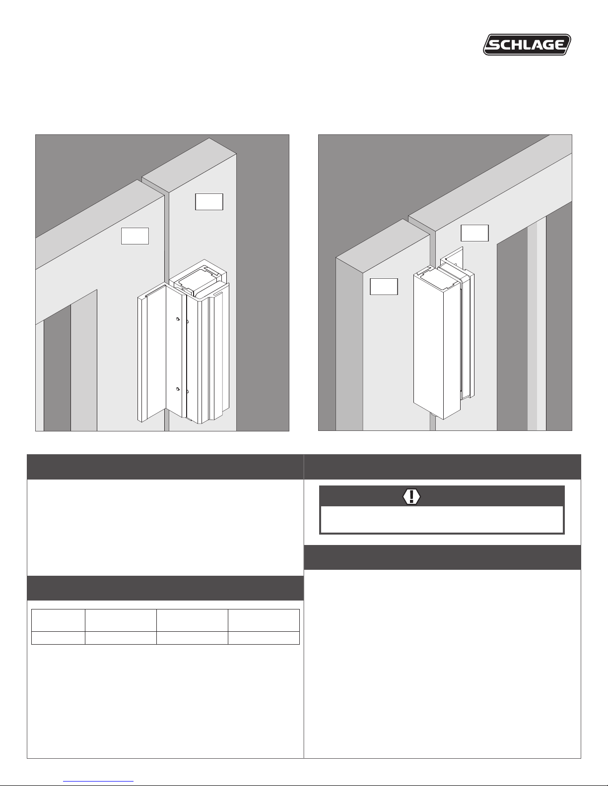
Swinging Application
For swinging application, go to page 3.
Gate
Installation Instructions
Sliding Application
For sliding application, go to page 5.
Post
Gate
Post
Features
Magnetic Bond Sensor (MBS)
Detects proper bond between magnet and armature. It can be
monitored remotely.
Door Position Switch (DPS)
Indicates whether door is open or closed. This feature is used in
conjunction with the MBS.
Electrical Specifications
Model
M490G 0.650 0.350 1500
Amps (12VDC)
Per Lock
Amps (24VDC)
Per Lock
Holding Force
(lbs) Per Lock
Warnings and Cautions
WARNING
Warnings indicate potentially hazardous conditions, which if not
avoided or corrected, may cause death or serious injury.
Pre-Installation Considerations
• Use ONLY the hardware provided for mounting this product.
• Follow the installation procedure as described in this manual.
• Operational temperature range is -31°F to 151°F (-35°C to 66°C).
• This product can be rehanded. Determine the proper door
handing before installing the product. See page 2 for rehanding
instructions.

Rehanding Instructions
1 Remove housing screws.
2 Slide out top endcap.
3 Slide out bottom endcap and magnet.
L Do not pull wires completely through.
5 Remove the bolts from both endcaps, flip 180° and
reinsert into bottom of endcaps.
NOTE: Be careful to not pinch any cables in the bottom endcap with the
screw!
A
B
6 Slide the magnet and bottom endcap into the
housing.
4 Flip the housing 180°.
2
7 Slide in the top endcap.
8 Insert and tighten endcap screws.

Swinging Lock Installation
1 Place template and mark holes.
a. Place template on gate and post surfaces as marked on
template.
b. Mark holes and prepare them per template.
LH
2 Install magnet assembly to non-moving post.
2a Attach L-Bracket to gate.
Actual Size (4x)
2b Attach mounting bracket to L-Bracket.
Actual Size (4x)
Actual Size (2x)
2c Attach magnet to bracket.
Actual Size (2x)
3
 Loading...