

Schlage M422,M452,M492 Installation Instructions Manual
*44487304*
44487304
M400 Series Double Locks
Double Electromagnetic Locks: M422, M452, M492
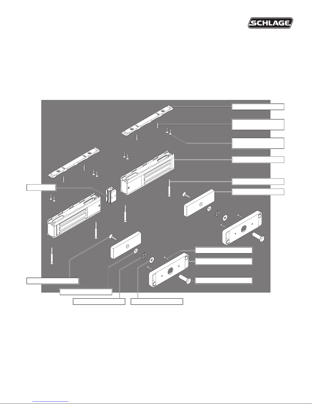
Joining Block
Installation Instructions
Mounting Bracket (2)
Inside Mounting Bracket
Screws** (4)
Outside Mounting Bracket
Screws** (8)
Magnet Assembly (2)
Magnet Screws (4)
Armature plate (2)
Armature Bolt*(2)
Armature Holder Screws (4)
Armature Holder (2)
Sex Nut (2)
Conical Washer (2)
Star Locking Washer (2) Flat Washer (2)
Features
Warnings and Cautions
Automatic Voltage Selection (AVS)
Magnet immediately detects 12VDC
or 24VDC when power is connected.
Anti-Tamper Switch (ATS)
An indication is provided should the magnet cover become
unsecured from lock.
Magnetic Bond Sensor (MBS)
Detects proper bond between magnet and armature. It can be
monitored remotely and locally with an LED.
LED
Provides local indication of MBS status.
Door Position Switch (DPS)
Indicates whether door is open or closed. This feature is used in
conjunction with the MBS.
Relock Time Delay (RTD)
Relock time can be changed. Range is 1 - 30 seconds.
Models
M422 (Trafc Control)
UL1034 and 10C/500 lb and 3 hr rating
M452 (High Security)
UL1034 and 10C/1000 lb and 3 hr rating
M492 (Max Security)
UL1034 and 10C/1500 lb and 3 hr rating
Trims
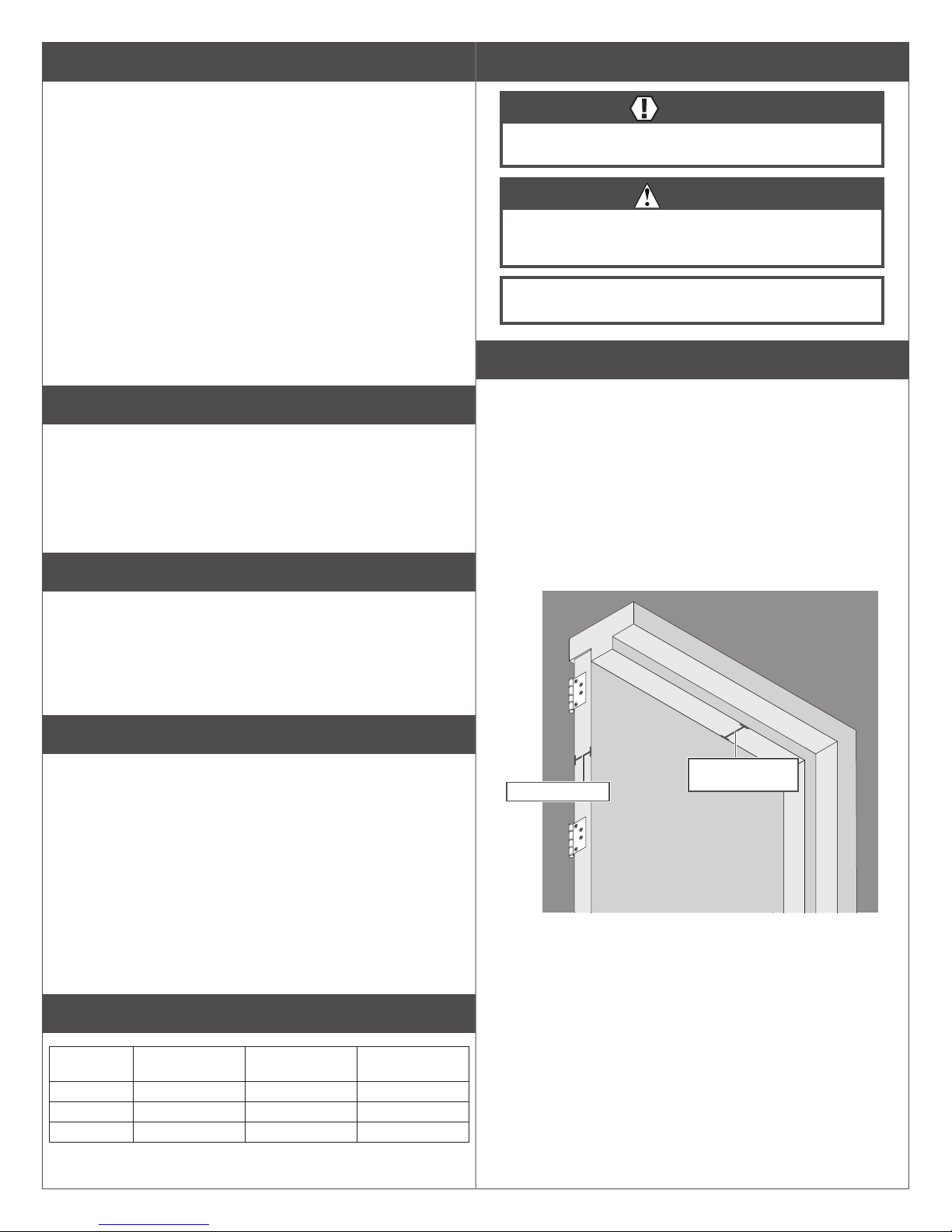
WARNING
Warnings indicate potentially hazardous conditions, which if not
avoided or corrected, may cause death or serious injury.
CAUTION
Cautions indicate potentially hazardous conditions, which if
not avoided or corrected, may cause minor or moderate injury.
Cautions may also warn against unsafe practices.
Caution: Cautions indicate a condition that may cause equipment
or property damage only.
Pre-Installation Considerations
• Use ONLY the hardware provided for mounting this product
(NOTE: Non-standard Door thickness may require different sex nut
hardware - see specic instructions for required hardware).
• Follow the installation procedure as described in this manual.
• Check door thickness. If the door is not 1C\v” thick, a different sex nut
will be required. Contact customer service at 1-877-671-7011.
• Check door header. A minimum 2C\v” thick, at surface is needed to
securely mount all screws for the magnet. If you do not have the
required surface, you will need ller plates and/or angle brackets to
properly mount the magnet.
Contact customer service at 1-877-671-7011.
Basic
Auto Voltage Selection (AVS) for 12 or 24VDC
Plus
Basic features + Door Position Switch (DPS), Magnetic Bond Sensor
(MBS), Relocking Time Delay (RTD), LED Status Indicator (LED) and
Anti-Tamper Switch (ATS)
UL Requirements
• Units shall not impair operation of panic hardware mounted on door.
• Units shall not impair intended operation of an emergency exit.
• Not to be used without UL approved latching hardware.
• Units/Models are intended to be connected to UL Listed Equipment, not
intended for Burglar or Fire Alarm Initiating or Indicating Devices.
• Ambient Conditions - “For Indoor Use Only”.
• Wiring methods shall be in accordance with the National Electrical Code,
ANSI/NFPA 70.
• This device complies with part 15 of FCC rules.
Operation is subject to following two conditions:
1. This device may not cause harmful interference.
2. This device must accept any interference received, including any
interference that may cause undesired operation. Changes or
modications not expressly approved by party responsible for compliance
could void user’s authority to operate equipment.
Electrical Specifications
Model Amps (12VDC)
Per Lock
M422 1.500 0.760 500
M452 1.500 0.760 1000
M492 1.300 0.700 1500
Amps (24VDC)
Per Lock
Holding Force
(lbs) Per Coil
Door: 1C\v” Thick
Header: At least
2C\v” thick, at
2
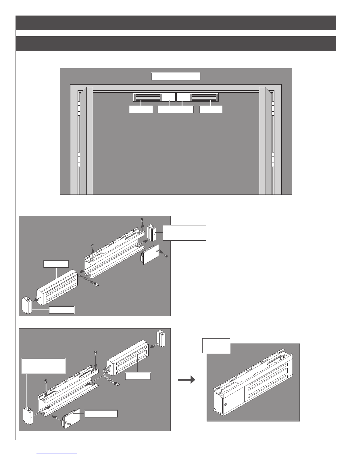
Lock Installation
1 Prepare for installation.
1a Determine proper magnet orientation.
Locks should be installed with wiring covers in the middle, so the magnet in one of the locks must be reoriented.
Shown from Exterior
Magnet MagnetWiring Covers
1b Reorient magnet (if necessary).
a. Remove screws, wiring cover and end blocks.
(with screw holes)
Magnet
End Block
b. Rotate magnet, end blocks and wiring cover as shown, then reassemble.
End Block
(with screw holes)
Magnet
End Block
Assembled
Magnet
Wiring Cover
3
1c Place template and mark holes.
a. Place template on top centerline of doors.
b. Mark holes and prepare them per template.
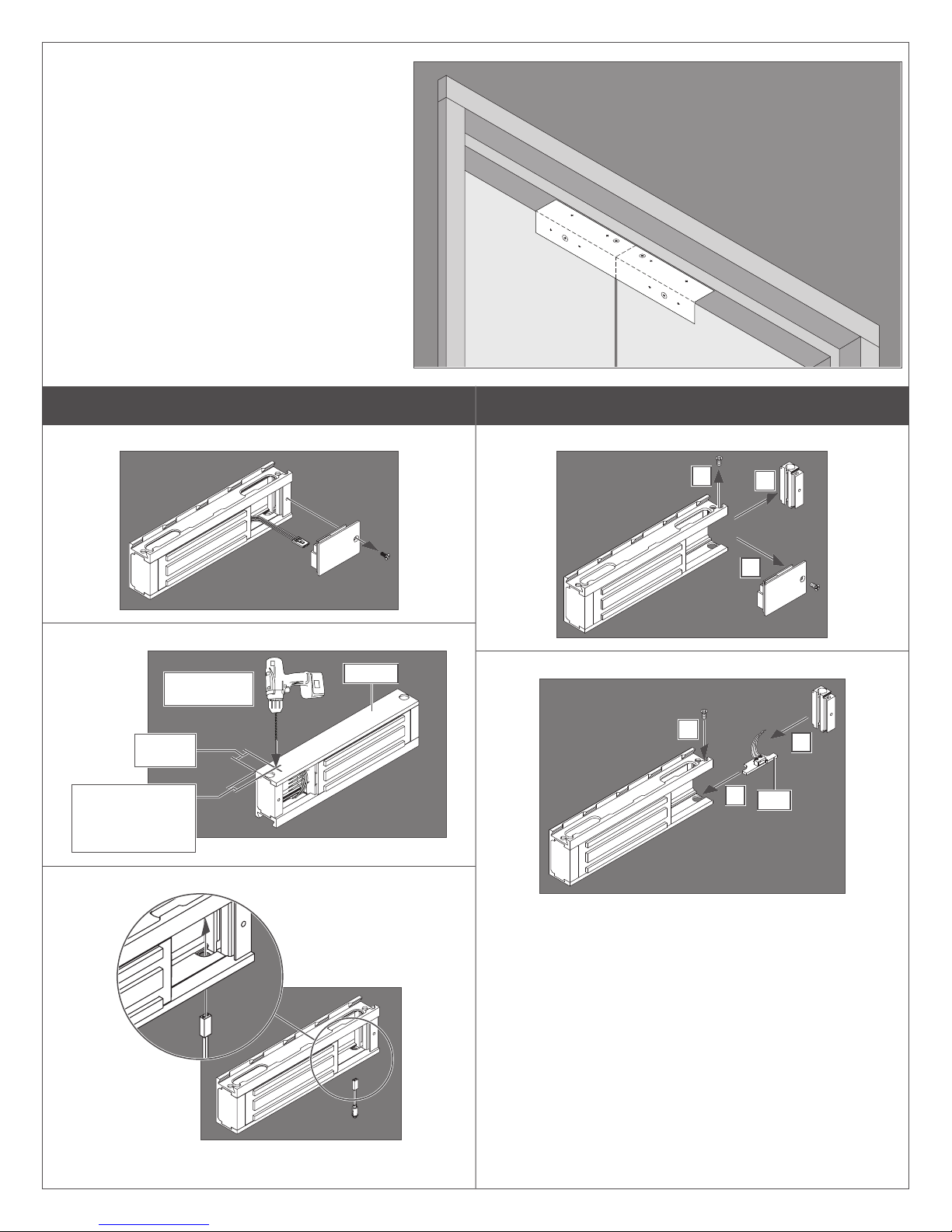
2 Install MBS indicator (optional, plus models ONLY).
2a Remove cover.
2b Drill hole for MBS indicator.
0.25” (6 mm)
hole/drill bit
0.75”
(19 mm)
M420: 0.50"
(13 mm)
M450/490: 0.75”
(19 mm)
Bottom
3 Install ATS (optional, plus models ONLY)
3a Remove end block and wiring cover.
b
3b Install ATS and Reassemble
c
c
a
b
a
ATS
2c Install MBS indicator.
4
 Loading...