

Schlage M420,M450,M490 Installation Instructions Manual
M400 Series
Electromagnetic Locks
Installation Instructions for Single Locks
M420, M450, M490
FEATURES
Automatic Voltage Selection (AVS)
Magnet immediately detects 12VDC or 24VDC when power
is connected.
Anti-Tamper Switch (ATS)
An indication is provided should the magnet cover become
unsecured from lock.
Magnetic Bond Sensor (MBS)
Detects proper bond between magnet and armature. It can
be monitored remotely and locally with an LED.
LED
Provides local indication of MBS status.
Door Position Switch (DPS)
Indicates whether door is open or closed. this feature is used
in conjunction with the MBS.
Relock Time Delay (RTD)
Relock time can be changed. Range is 1 - 30 seconds.
UL Requirements:
• Units shall not impair operation of panic hardware mounted on door.
• Units shall not impair intended operation of an emergency exit.
• Units/Models are intended to be connected to UL Listed Equipment, not
intended for Burglar or Fire Alarm Initiating or Indicating Devices.
• Ambient Conditions - “For Indoor Use Only”
MODELS
M420 (Traffi c Control)
UL1034 and 10C/500lb and 3hr rating
M450 (High Security)
UL1034 and 10C/1000lb and 3hr rating
M490 (Max Security)
UL1034 and 10C/1500lb and 3hr rating
TRIMS
Basic
Auto Voltage Selection (AVS) for 12 or 24VDC
Plus
Basic features + Door Position Switch (DPS), Magnetic Bond
Sensor (MBS), Relocking Time Delay (RTD), LED Status
Indicator (LED) and Anti-Tamper Switch (ATS)
This device complies with part 15 of FCC rules.
Operation is subject to following two conditions:
1. This device may not cause harmful interference.
2. This device must accept any interference received, including any
interference that may cause undesired operation. Changes or modifi cations
not expressly approved by party responsible for compliance could void
user’s authority to operate equipment.
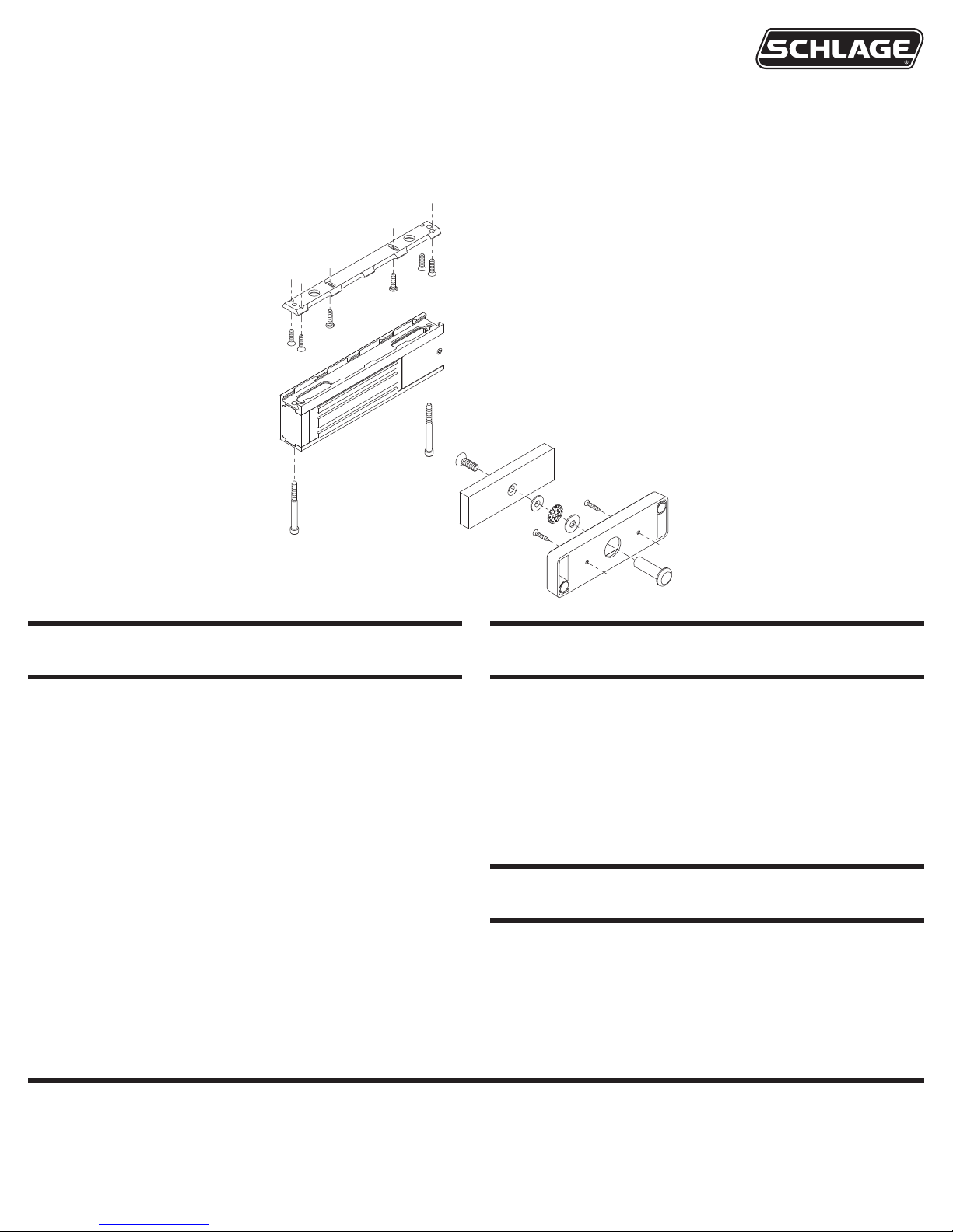
ELECTRICAL SPECIFICATIONS
Magnet
Wiring Cover
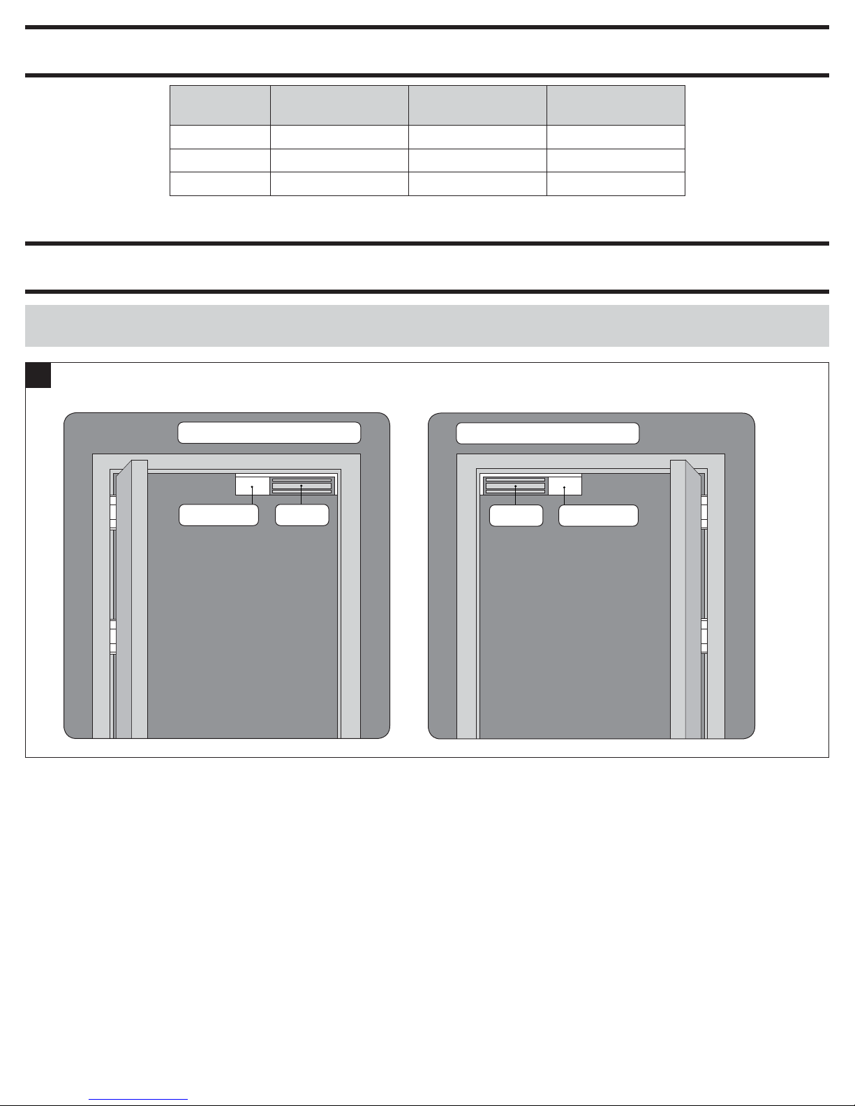
LHR Door - Shown from Exterior
Magnet
Wiring Cover
RHR Door - Shown from Exterior
Model
M420 0.750 0.380 500
M450 0.750 0.380 1000
M490 0.650 0.350 1500
1 PREPARE FOR INSTALLATION
1a
Determine Proper Magnet Orientation
• Magnet should be placed opposite of door hinges.
Amps (12VDC)
Per Lock
Amps (24VDC)
LOCK INSTALLATION
Per Lock
Holding Force
(lbs) Per Coil
2
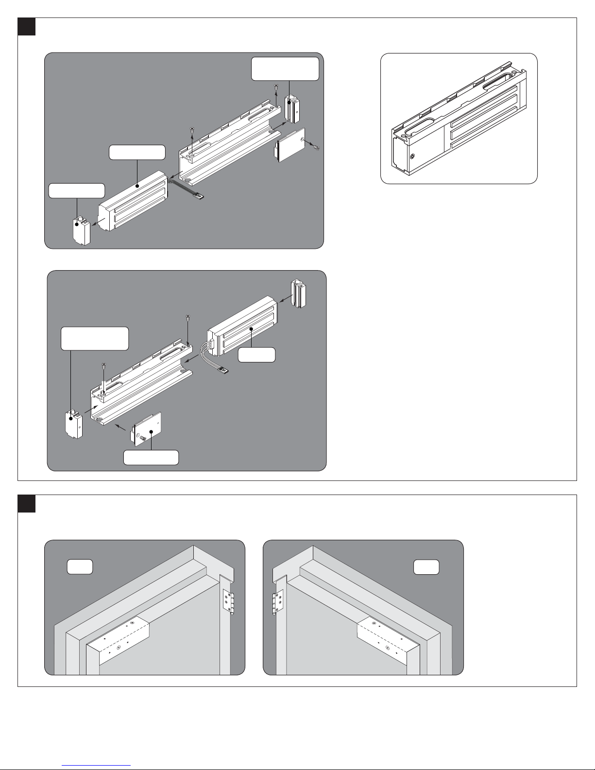
1b
End Block
Magnet
End Block
(with screw hole)
Magnet
Wiring Cover
End Block
(with screw hole)
LHR
RHR
Reorient Magnet (if necessary)
• Remove screws, wiring cover and end blocks.
• Rotate magnet, end blocks and wiring cover as shown, then reassemble.
1c
Place Template and Mark Holes
• Place template on top corner, opposite of hinges.
• Mark holes and prepare them per template.
3
 Loading...