

Schlage L Series,L909X Series,LM929X Series Wiring Instructions And Specifications
*P516-871*
P516-871
L-Series Electried Locks
L909X-Series Electried Mortise Lock,
LM929X-Series Electried Two-Point Lock
Wiring Instructions and Specications
WARNINGS
Warnings indicate potentially hazardous conditions, which if not
avoided or corrected, may cause death or serious injury.
WARNING
L-Series Electried Lock
All installations should be in accordance with local electrical codes and national electrical code, NFPA 70.
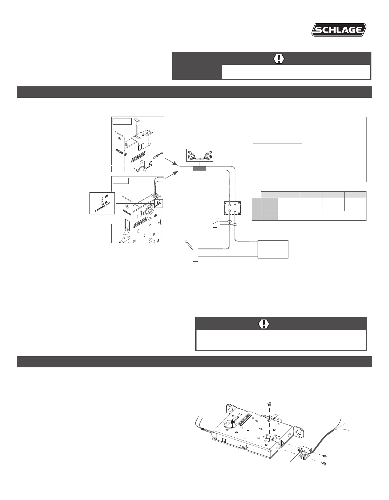
L909X-Series and LM929XSeries electried locks offer
selection between one of
two modes, EL or EU.
Select the appropriate mode
for the installation using the
mode select switch located
on the mortise chassis.
EL, electrically locked
(fail safe):
Outside knob/lever or both
outside and inside knobs/
levers (depending on
function) will lock when
power is applied. In the
event of power failure, the
opening will be unlocked.
Mode select
EU, electrically unlocked
(fail secure):
Outside knob/lever or both
outside and inside knobs/
levers (depending on
function) will unlock when
power is applied. In the
event of power failure, the
opening will be locked.
Note: When mode is switched (from EL to EU or EU to EL) the lock requires a complete lock/unlock power cycle to synchronize to
the proper mode.
IMPORTANT! Connection of L-Series electried mortise locks to a supply circuit containing electromagnetic devices (i.e., solenoid based) is not
recommended. If used, the resulting transient voltages could damage the lock. The transient voltage must be carefully suppressed at the equipment
producing it before connecting the lock to the same circuit. A varistor rated at 35 V (peak recurrent) may be used for transient voltage protection.
Troubleshooting
If lock does not operate.
• Ensure the lock is powered with DC power. Do not use AC power.
• Ensure the input voltage is between 10.8 and 26.4 volts DC.
switch
LM929X
L909X
Lock to hinge/EPT
harness (not furnished)
Electried hinge/
EPT (not furnished)
Install varistor
here if used
(not furnished)
Switch
(not furnished)
Electrical Requirements:
The L909X and LM929X-Series electried locks
are powered by DC power only.
Do not use AC power.
• Voltage: 12 or 24 VDC (maximum 26.4 V,
minimum 10.8 V)
• Peak current: 0.4 amps
• Holding current: 0.010 amps
• Operating temperature: -22°F to 140°F
(-30°C to 60°C)
Maximum Total Wire Length
AWG 14 16 18 20
12 or 24 V DC
12 V
24 V Up to 1000' 304 m
Voltage
Note: Either lock wire may be attached to either power
supply terminal (+ or -).
Power supply
12 or 24 V DC
(not furnished)
500'
(152 m)
300'
(91 m)
200'
(61 m)
100'
(30 m)
WARNING
L9091/93/95, L9493/95 and LM9291/93/95 functions lock both inside and
outside levers. Locking both levers will prevent normal egress from the
inside and will prevent the intended operation of an emergency exit.
L-Series Request-to-Exit (RX) Lock
RX utilizes a microswitch inside the lock case to detect rotation of the inside knob/lever. The switch then signals the use of the opening to the security system.
The RX is a removable module located on the bottom edge of the lock chassis. The module must be properly positioned to detect inside knob/lever
rotation. If not properly positioned, the lock and/or microswitch may be damaged.
Note: RX is not applicable with LM929X-Series locks.
RX module installation
1. The microswitch must be on the same side of the door as the
handing screw (facing the inside of the door).
2. Install the RX switch module as shown.
Change lock handing with RX
1. If the RX module is installed, remove the RX module.
2. Remove the handing screw.
3. Rotate the latch 180° (if necessary).
4. Reinstall the handing screw on the appropriate side.
5. Reinstall the RX module with the microswitch on the same side as
the handing screw.
Electrical rating: 3 A, 125 V AC; 2 A, 30 V DC
Handing screw
Microswitch
Blue (NO)
RX module
screws
Yellow (NC)
Green
(common)

Deadbolt Monitor (DM)
1
2
3
4
5
6
7
8
1
2
1
4
Deadbolt Monitor (DM) identies the status of the deadbolt (extended or retracted). Normally open, normally closed, and common connections are
provided. Note: Deadbolt monitor is only available on deadbolt models. Electrical rating: 3 A, 125 V AC; 2 A, 30 V DC.
Latchbolt Monitor (LX)
Latchbolt Monitor (LX) identies the status of the latchbolt (extended or retracted). Normally open, normally closed, and common connections
are provided. Electrical rating: 3 A, 125 V AC; 2 A, 30 V DC.
Door Position Sensor (DPS)
Door Position Sensor (DPS) detects the position of the door, open
or closed, by utilizing a sensor in the mortise lock to detect a magnet
located in the door strike. Normally open, normally closed, and common
DPS strike box
Magnet
connections are provided. Note: DPS is not available on deadbolt models.
Max voltage 175 VDC, max current 0.250 A
Strike
(10-072 shown)
Allegion Connect
The L909X-Series and LM929X-Series electried mortise locks are furnished with Allegion Connect, a factory-installed Molex® connector system that
provides simplied installation and maintenance. The system utilizes quick-connect harnesses and hinges. As an alternative installation method, the
Molex connector may be cut off and the lock installed with traditional wire splicing methods.
Note: The items listed and shown below reect options that may or may not be included with your specic model.
RX/LX/DPS
L909X available options:
RX = Request to exit
DM = Deadbolt monitor
DPS = Door position sensor
LX = Latchbolt monitor
See charts below for wire colors.
LM929X available options:
None
4-pin
connector
8-pin
connector
3
4
5
6
7
8
2
3
Variable length wiring
RX/LX/DM
8-Pin
Purpose Function
EL / EU
RX
LX
Power* Black 1▬►
Power* Black 2
Normally Open (NO) Blue 3▬►
Normally Closed (NC) Yellow 4
Common (C) Green 5
Normally Open (NO) Gray 6▬►
Normally Closed (NC) Violet 7
Common (C) White 8
harness (6" to 192")
Lock
Connector
Wire
Color
Pin Pin
EPT or electried hinge
Harness
Connector
Wire
Color
►
►
►
►
►
1 Red
2 Black
3 Blue
4 Yellow
5 Green
6 Gray
7 Violet
8 White
▬
▬
▬
▬
▬
4-Pin
Purpose Function
Normally Open (NO) Orange 1
DM
DPS
Normally Closed (NC) Brown 2
Common (C) Pink 3
not used 4 4 Ta n
Normally Open (NO) Green/black 1
Normally Closed (NC) Red 2
Common (C) White/black 3
not used 4 4 Ta n
Lock
Connector
Wire
Color
6” wiring harness
Connector
Pin Pin
▬
►
1 Orange
▬
►
2 Brown
▬
►
3 Pink
▬
►
1 Orange
▬
►
2 Brown
▬
3 Pink
►
Harness
Wire
Color
To
power
supply
* Lock auto-detects GND, +12 or +24 V DC
Customer Service
1-877-671-7011 www.allegion.com/us
© Allegion 2015
Printed in U.S.A.
P516-871 Rev. 10/15-d
 Loading...