

Schlage L Series,L909X Series,L949X Series,LM929X Series Wiring Instructions And Specifications
*P516-871*
P516-871
L-Series Electried Locks
L909X/L949X-Series Electried Mortise Lock,
LM929X-Series Electried Two-Point Lock (not
UL/ULC Listed)
WARNINGS
Warnings indicate potentially hazardous conditions, which if not
avoided or corrected, may cause death or serious injury.
WARNING
Wiring Instructions and Specications
L-Series Electried Lock
All installations should be in accordance with local electrical codes and national electrical code, NFPA 70.
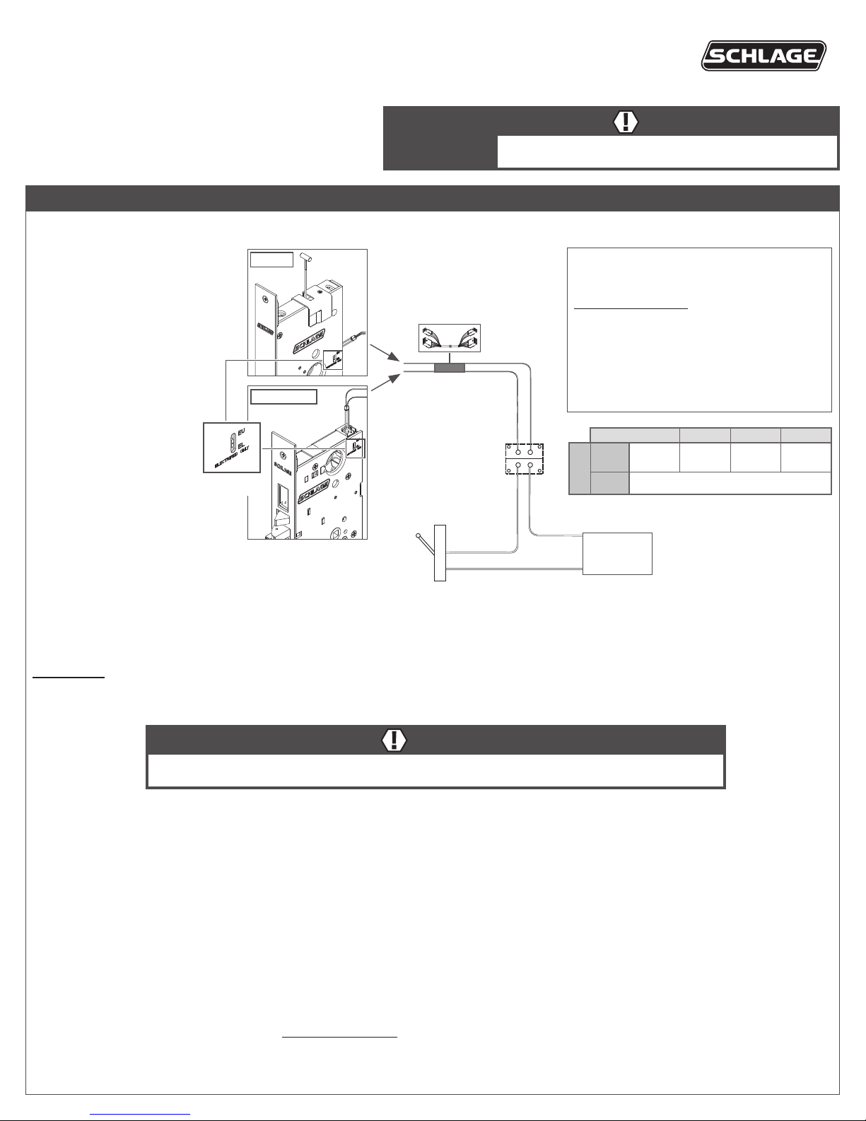
L909X/L949X-Series and
LM929X-Series electried
locks oer selection between
one of two modes, EL or EU.
Select the appropriate mode
for the installation using the
mode select switch located
on the mortise chassis.
LM929X
Lock to hinge/EPT
harness (not furnished)
EL, electrically locked
(fail safe):
switch
L909X/L949X
Electried hinge/
EPT (not furnished)
Outside knob/lever or both
outside and inside knobs/
levers (depending on
function) will lock when
power is applied. In the
event of power failure, the
opening will be unlocked.
Mode select
EU, electrically unlocked
(fail secure):
Outside knob/lever or both
outside and inside knobs/
levers (depending on
function) will unlock when
power is applied. In the event
of power failure, the opening
will be locked.
Switch
(not furnished)
12 or 24 V DC
Note: When mode is switched (from EL to EU or EU to EL) the lock requires a complete lock/unlock power cycle to synchronize to
the proper mode.
IMPORTANT! Connection of L-Series electried mortise locks to a supply circuit containing electromagnetic devices (i.e., solenoid based) is not
recommended. If used, the resulting transient voltages could damage the lock. The transient voltage must be carefully suppressed at the equipment
producing it before connecting the lock to the same circuit. A varistor rated at 35 V (peak recurrent) may be used for transient voltage protection.
Electrical Requirements:
The L909X/L949X and LM929X-Series
electried locks are powered by DC power only.
Do not use AC power.
• Voltage: 12 or 24 VDC (maximum 26.4 V,
minimum 10.8 V)
• Peak current: 0.4 amps
• Holding current: 0.010 amps
• Operating temperature: 32°F to 120°F (0°C
to 49°C)
• Maximum relative humidity 93%
AWG 14 16 18 20
12 V
24 V Up to 1000' (304 m)
Voltage
Note: Either lock wire may be attached to either power
supply terminal (+ or -).
Power supply
12 or 24 V DC
(not furnished)
500'
(152 m)
300'
(91 m)
200'
(61 m)
100'
(30 m)
WARNING
L9091/93/95, L9493/95 and LM9291/93/95 functions lock both inside and outside levers. Locking both levers
will prevent normal egress from the inside and will prevent the intended operation of an emergency exit.
Lock installation conditions and UL statements (applies only to L909X/L949X-Series locks):
• The lock shall be installed so as not to interfere with the intended operation of panic hardware installed on the same door.
• The lock shall be installed with a handle and spindle that meet the requirements of the ULC-S319 torque test or that are designed to sheer and
not cause damage to the lock at a torque less than 305 N-m.
• All interconnected equipment must be UL/ULC Listed.
• Lock to be powered by a power-limited class 2, UL 294/UL 603 and ULC-S318/ULC-S319 Listed power supply capable of supplying 12/24 VDC.
• External source for RX, DM, LX, and DPS shall be a UL Listed power source with Class 2, power-limited output.
• For ULC-S319 Class II, III and IV installations, the door must be provided with a door position switch.
• UL 294 Access Control Performance Levels: Destructive Attack, Level 1; Line Security, Level 1; Standby Power, Level 1; Endurance, Level IV
(with DM, or LX, Endurance, Level I).
• ULC-S319 Class III
Troubleshooting
If lock does not operate:
• Ensure the lock is powered with DC power. Do not use AC power.
• Ensure the input voltage is between 10.8 and 26.4 volts DC.
L-Series Request-to-Exit (RX) Lock
RX utilizes a microswitch inside the lock case to detect rotation of the inside knob/lever. The switch then signals the use of the opening to the security
system. The RX is a removable module located on the bottom edge of the lock chassis. The module must be properly positioned to detect inside knob/lever
rotation. If not properly positioned, the lock and/or microswitch may be damaged. Default status for normally open or normally closed is with door open.
Use of RX module not evaluated by UL.
Note: RX is not applicable with LM929X-Series locks.
RX module installation
1. The microswitch must be on the same side of the door as the
handing screw (facing the inside of the door).
2. Install the RX switch module as shown.
Handing screw
Blue (NO)
Yellow (NC)
Change lock handing with RX
1. If the RX module is installed, remove the RX module.
2. Remove the handing screw.
Green
(common)
3. Rotate the latch 180° (if necessary).
4. Reinstall the handing screw on the appropriate side.
5. Reinstall the RX module with the microswitch on the same side
as the handing screw.
Microswitch
RX module
screws
Electrical rating: 2 A, 30 V DC, Resistive or 1 pf
Deadbolt Monitor (DM)
Deadbolt Monitor (DM) identies the status of the deadbolt (extended or retracted). Normally open, normally closed, and common connections are
provided. Note: Deadbolt monitor is only available on deadbolt models.
Default status for normally open or normally closed is with the deadbolt retracted. Closing the door or extending the deadbolt reverses the status.
Electrical rating: 2 A, 30 V DC, Resistive or 1 pf
Latchbolt Monitor (LX)
Latchbolt Monitor (LX) identies the status of the latchbolt (extended or retracted). Normally open, normally closed, and common connections
are provided.
Default status for normally open or normally closed is with the door open.
Electrical rating: 2 A, 30 V DC, Resistive or 1 pf
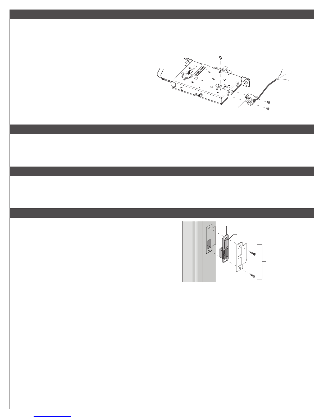
Door Position Sensor (DPS)
Door Position Sensor (DPS) detects the position of the door, open
or closed, by utilizing a sensor in the mortise lock to detect a magnet
located in the door strike. Normally open, normally closed, and common
connections are provided.
Default status for normally open or normally closed is with the door open.
Note: DPS is not available on deadbolt models.
Max voltage: 30 V DC, max current 0.250 A
DPS strike box
Magnet
Strike
(10-072 shown)
 Loading...