

Schlage L400 Series Installation Instructions Manual
*P516-911*
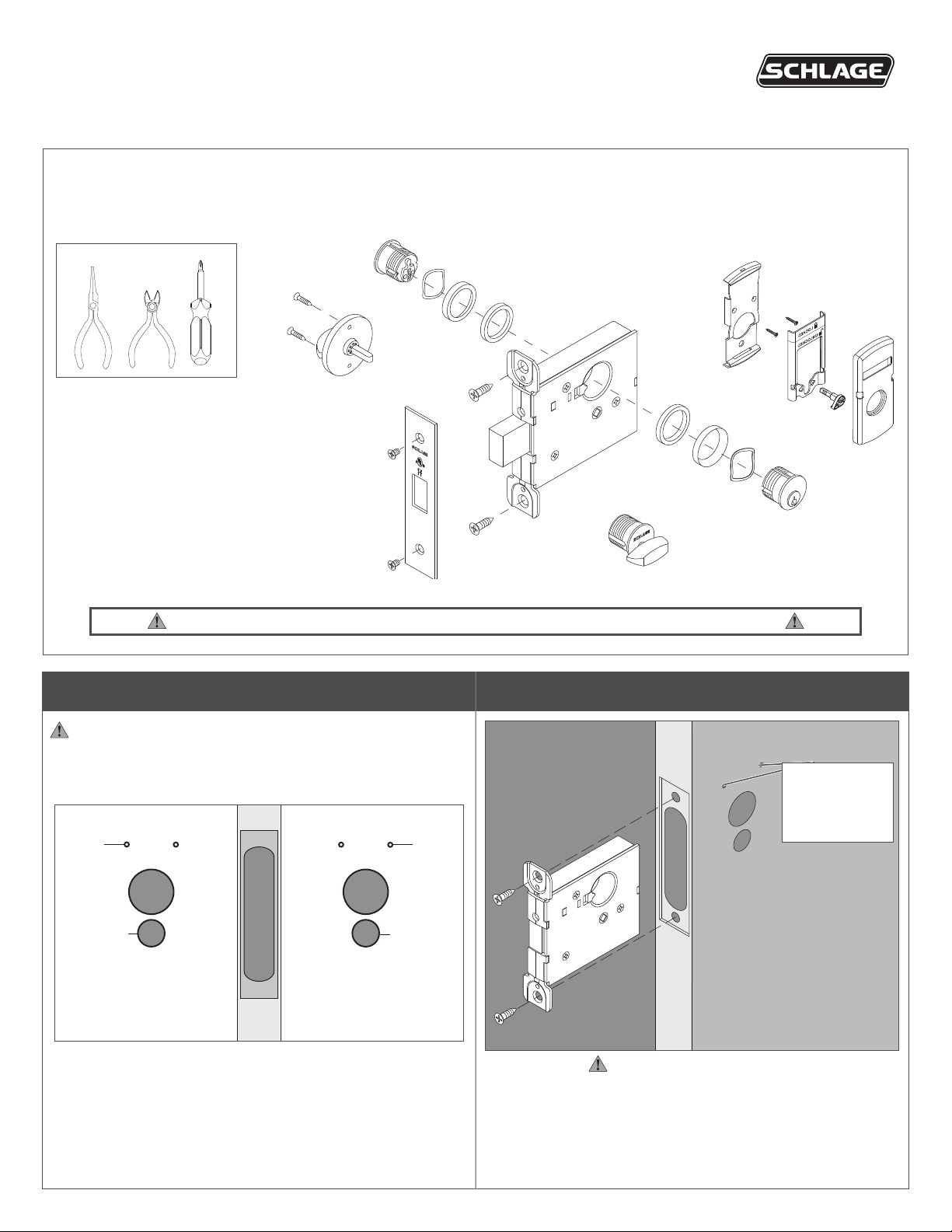
L400 Lock with Indicator
P516-911
L400 Series Lock with Indicator Sectional Trim
Indicator trim is available for either the inside or outside of the door on allowable functions.
Non-indicator trim is furnished on the opposite side of the door.
The L400 lock with indicator is not intended for exterior door applications.
For retrot, see page 6.
Installation Instructions
Tools
Thumb turn
Check the door preparation dimensions with the template included in the package.
1 Prepare the door for indicator trim
Indicator trim
Cylinder turn
2 Install lock chassis
Two Z\," pilot holes are required to mount the indicator.
ONLY ONE SIDE OF THE DOOR – THE INDICATOR SIDE –
REQUIRES THIS PREPARATION. Use the template included in
the package to mark the location of the pilot holes before drilling.
¹⁄₈" pilot
hole x 2
For indicator
thumb turn
only
Inside of door Outside of door
¹⁄₈" pilot
hole x 2
For indicator
thumb turn
only
Note:
Pilot holes for
INDICATOR
ONLY
DO NOT FULLY TIGHTEN
CHASSIS MOUNTING SCREWS.

3 Install outside cylinder - NON-INDICATOR ONLY
FOR INDICATOR, SKIP TO STEP 4.
4b Adjust the cam spindle length.
3a Insert key halfway into the cylinder.
Exterior
3b Rotate cylinder clockwise.
L463
Key inserted
halfway
Cut the spindle at the appropriate mark
according to door thickness.
For 2Z\v” door do not cut the spindle.
4c Install the indicator slide and cam.
Indicator
slide
Cam
4d Connect the cam to the indicator slide. The cam must
engage either the left or right side of the indicator slide
according to door handing and indicator location.
• Unlock the door.
• Move the indicator slide against the top rim of the
mounting plate (unlocked position).
• Assemble the cam as shown.
Door Hand/Indicator Location
4 Install outside cylinder - INDICATOR
4a Install the indicator mounting plate.
Mounting plate
Lock Type
Non-deadbolt
functions
Deadbolt
functions
RH/Outside
LH/Inside
RH/Inside
LH/Outside
RH/Inside
LH/Outside
RH/Outside
LH/Inside
2
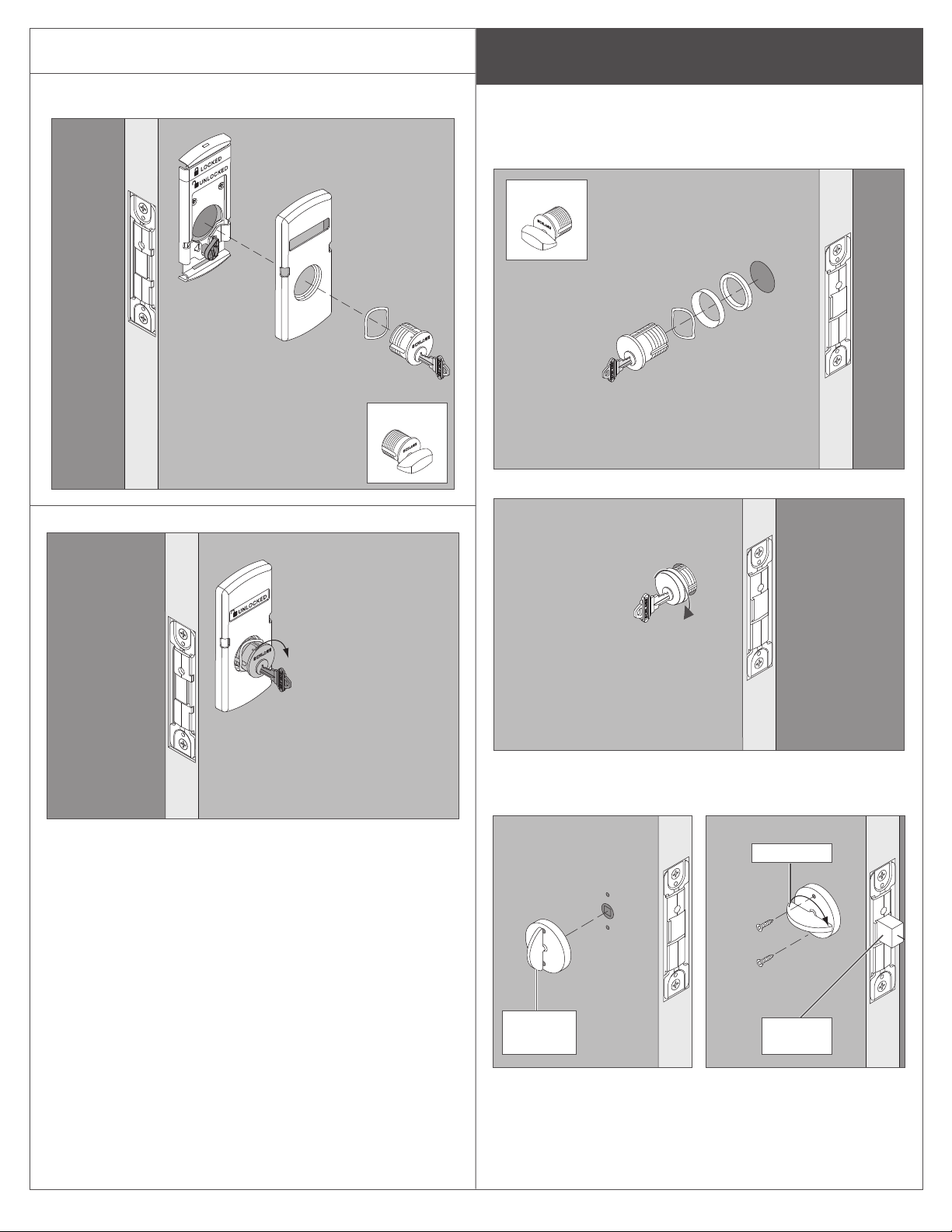
4e Insert key halfway into the cylinder.
4f Install the indicator faceplate and cylinder with cylinder
spring as shown.
L463
5 Install inside cylinder or thumb turn –
NON-INDICATOR ONLY
FOR INDICATOR, SKIP TO STEP 6.
Cylinder
5a Insert key halfway into the cylinder.
L463
5b Rotate cylinder clockwise.
4g Rotate cylinder clockwise.
— OR —
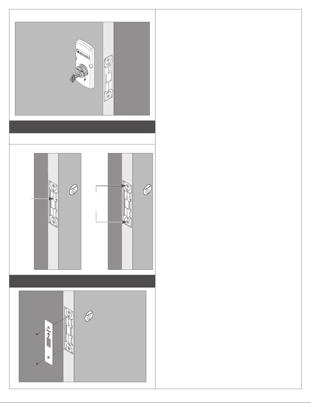
Thumb turn
Rotate 180°
Thumbturn
vertical
Extend
deadbolt
3

6 Install inside cylinder – INDICATOR
6a Install the indicator mounting plate.
Mounting plate
6b Adjust the cam spindle length.
Cut the spindle at the appropriate mark
according to door thickness
For 2Z\v” door do not cut the spindle.
6c Install the indicator slide and cam.
6d Connect the cam to the indicator slide. The cam must
engage either the left or right side of the indicator slide
according to door handing and indicator location.
• Unlock the door.
• Move the indicator slide against the top rim of the
mounting plate (unlocked position).
• Assemble the cam as shown.
Door Hand/Indicator Location
Lock Type
Non-deadbolt
functions
Deadbolt
functions
RH/Outside
LH/Inside
RH/Inside
LH/Outside
RH/Inside
LH/Outside
RH/Outside
LH/Inside
6e Insert key halfway into the cylinder.
6f Install the indicator faceplate and cylinder with cylinder
spring as shown.
L463
Indicator
slide
Indicator
faceplate
Key inserted
halfway
Cam
4
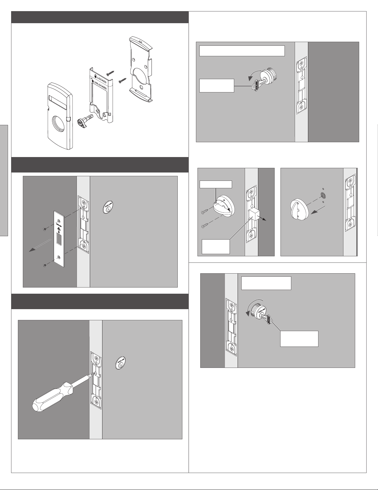
6g Rotate cylinder clockwise.
7
7a Tighten cylinder mounting screw.
7b Tighten top and bottom chassis mounting screws.
For retrofit instructions, see page 6.
a
Cylinder
mounting
screw
8 Install armor front
b
Chassis
mounting
screws
5
INDICATOR LOCK RETROFIT INSTRUCTIONS
1 Remove armor front
2b Remove the inside cylinder or thumb turn.
Cylinder
Rotate cylinder counterclockwise
Key inserted
halfway
— OR —
Thumb turn
Rotate 180°
2 Remove cylinder(s) or thumb turn if applicable
2a Loosen the cylinder mounting screw.
Extend
deadbolt
2c Remove the outside cylinder.
Rotate cylinder
counterclockwise
Key inserted
halfway
6
 Loading...