

Schlage KING COBRA,KING COBRA-2,KC9111-2,KC9321,KC9321-2,KC9111 Installation Manual

KING COBRA/KING COBRA-2
NARROW STILE SERIES
KC9111/KC9111-2 KC9321/KC9321-2
Keypad Programmable
and SNAP Compatible Trim
For Narrow Stile Doors
57040-E 04-2007
KC9111/KC9111-2 & KC9321/KC9321-2 INSTALLATION
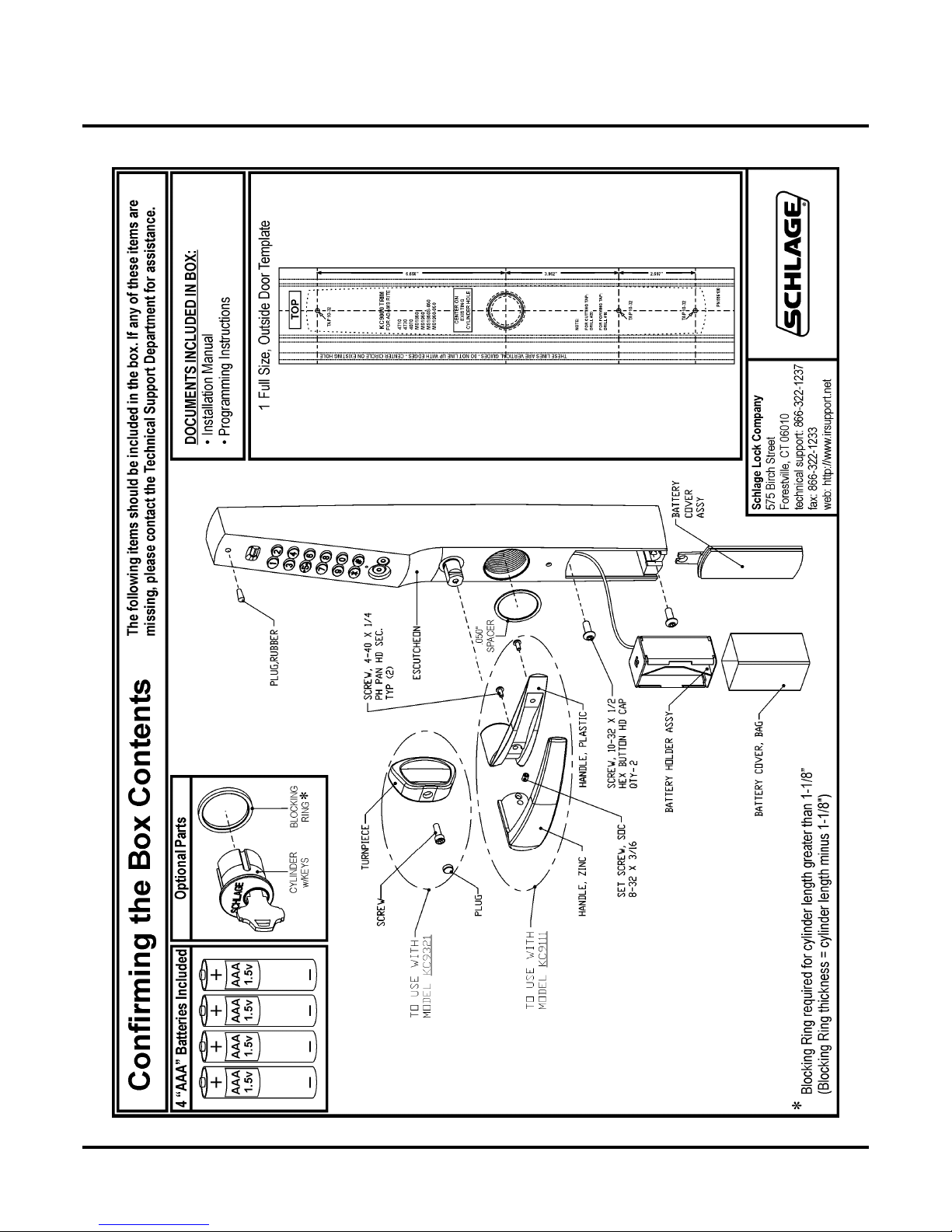
Contents of the Box
KC9111/KC9111-2 & KC9321/KC9321-2 INSTALLATION
Contents of the Box
57040-E Page 2 04-2007

KC9111/KC9111-2 & KC9321/KC9321-2 INSTALLATION
1
1/8” wide blad
Introduction / Tools and Materials Needed / Contact Info
Introduction / Tools and Materials Needed / Contact Info
Introduction:
The KC9111/KC9111-2 and KC9321/KC9321-2 are designed to replace existing
exterior trim on Adams Rite® deadlatches. The trim will retract the latch when an
access code or iButton is entered and the lever is depressed or the turnpiece is
turned. Mechanical key override is standard. The trim is compatible with any interior device such as a pushpaddle or Adams Rite® mortise exit device. When a
‘toggle’ code or iButton is entered the lever or turnpiece will be continuously
engaged allowing latched passage mode until a ‘toggle’ code or iButton is entered
again to relock trim. Audit Trail feature is available on the KC9111-2 & KC9321-2
The KC9111/KC9111-2 (trim w/lever & MS Hook interface) and the KC9321/
KC9321-2 (trim w/turnpiece & MS Hook interface) are both compatible with
Adams Rite® 4710 & 4730 deadlatch locks and 8400 Series mortise narrow
stile exit devices.
Tools and Materials Needed:
.Flat head screwdriver w/straight,
2. Small Philips head screwdriver
3. 3/32” Allen wrench
4. 1/16” Allen wrench
5. Long nose needle-nose pliers
6. Center punch
7. Hammer
8. Pencil
9. Drill & Tap for 10-32 threads
e.
Contact Information:
Schlage Lock Company
575 Birch Street
Forestville, CT 06010
technical support: 866-322-1237
fax: 866-322-1233
web: http://www.irsupport.net
57040-E Page 3 04-2007
KC9111/KC9111-2 & KC9321/KC9321-2 INSTALLATION
Door Preparation
Door Preparation
Door Conditions:
Installation may require the use of a cover plate (a) to cover the holes left in the door.
If the KC9321/KC9321-2 (trim w/turnpiece) is used and the existing pull (b) must be
removed, Ives offers a compatible pull.
>Schlage Cover Plate P/N: KC9000-KRP
>Ives Pull P/N: 8190-18-xxx (xxx = finish)
Backset is determined by
the Adams Rite® lock.
b
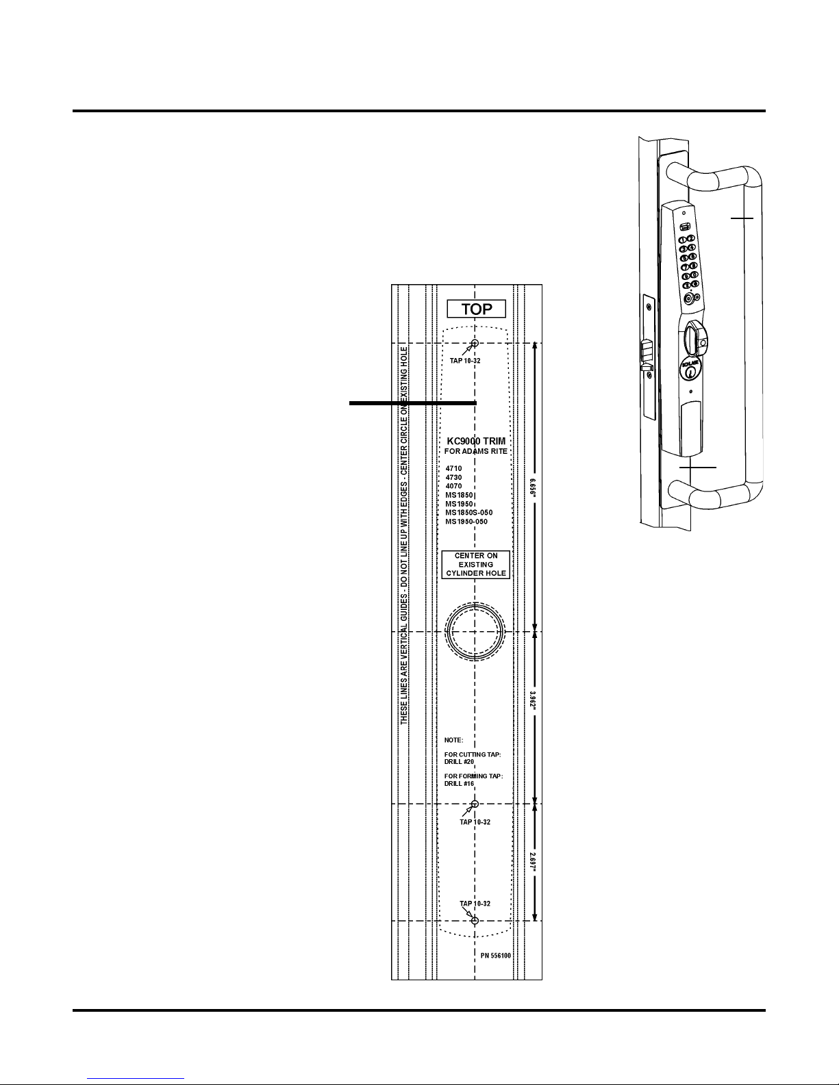
For factory prepped doors, use dimensions
shown. Dimensions are referenced from center of 1-1/4” cylinder hole. Backset is determined by the Adams Rite® lock.
When installing new Adams Rite® locks,
do not install outside cylinder (because this
trim replaces it) and do not install face plate at
this time because access to the cylinder set
screw in the lock will be required during
installation.
a
6-21/32”
(6.656”)
3-31/32”
(3.962”)
2-45/64”
(2.697”)
57040-E Page 4 04-2007
KC9111/KC9111-2 & KC9321/KC9321-2 INSTALLATION
C9000
108
016
C9000
1/8”
N
Cams, Cores, Cylinders and Blocking Rings
Cams, Cores, Cylinders and Blocking Rings
Cams For Mechanical Override Cylinder:
The K
is a list of compatible Schlage parts. For other manufacturers,
consult cross-reference charts.
> Cam for Standard Mortise cylinder: Schlage Everest: L583-153
Schlage Classic: L583-254
> Cam for Interchangeable Core: Schlage IC Cam: L583-255
trim requires the use of a clover leaf cam (a). This
IC Cores:
> Small Format IC core w/ cam: Schlage: 80-
NOTE: This core requires the use of 1/4” blocking ring:
Schlage: 36-079-025-<FINISH>
-<FINISH>
a
> Full Size IC core w/ cam: Schlage: 30-
NOTE: This core requires the use of 3/8” blocking ring:
Schlage: 36-079-037-<FINISH>
-<FINISH>
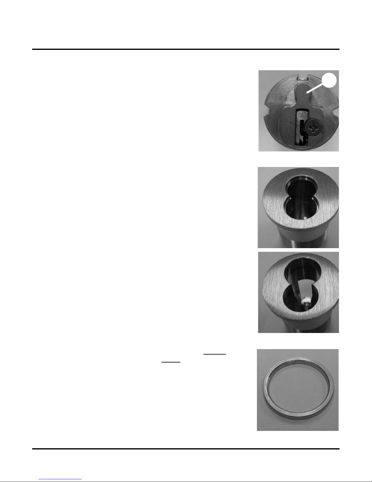
Cylinders / Blocking Rings:
The K
of a blocking ring. For cylinders longer
ring is required. The blocking ring thickness is equal to the cylinder length, minus 1-1/8”. For example, if you use a 1-1/2” cylinder you need a 3/8” blocking ring. Compression rings can be
ordered from a Schlage distributor:
Thickness: Schlage Part Number:
o compression ring: 1/8” 36-079-012-<FINISH>
1/4” 36-079-025-<FINISH>
3/8” 36-079-037-<FINISH>
1/2” 36-079-050-<FINISH>
can use a 1-
mortise cylinder without the use
than 1-1/8” a blocking
57040-E Page 5 04-2007
KC9111/KC9111-2 & KC9321/KC9321-2 INSTALLATION
1/8” l
Installing the KC9111/KC9111-2 or KC9321/KC9321-2
Installing the KC9111/KC9111-2 or KC9321/KC9321-2
Installing the KC9111/KC9111-2 or KC9321/KC9321-2
If your trim has a key cylinder already installed, skip to Determine Hand: on page 12. Otherwise, continue with Loosen the Baseplate Screws: on this page.
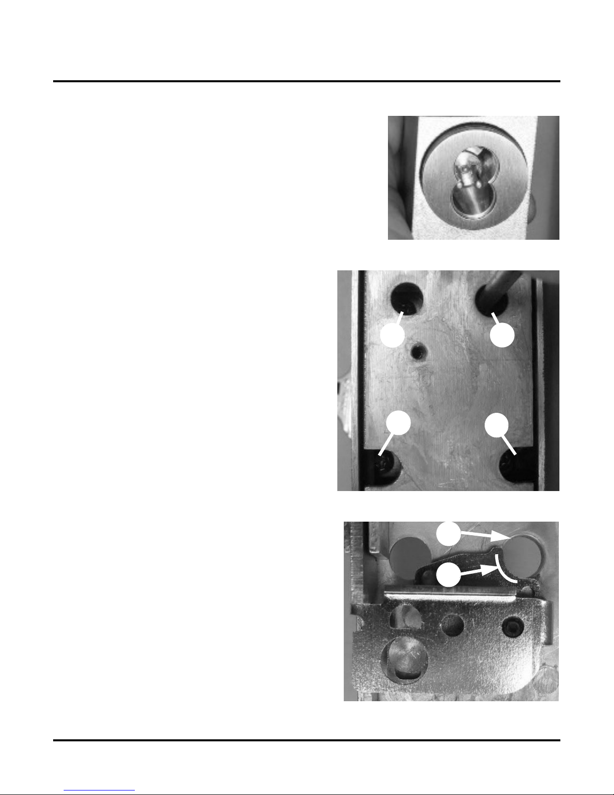
1) Loosen the Baseplate Screws:
IMPORTANT: Do not remove any of the screws in the following step or it will be difficult to reinstall them.
• Using a small Philips head screwdriver, loosen
screws a & b in baseplate, around key cylinder
hole, one turn.
NOTE: Screws a, b, c & d are set at the factory.
Screws a & b are tightened and screws c & d are left loose.
c
d
a
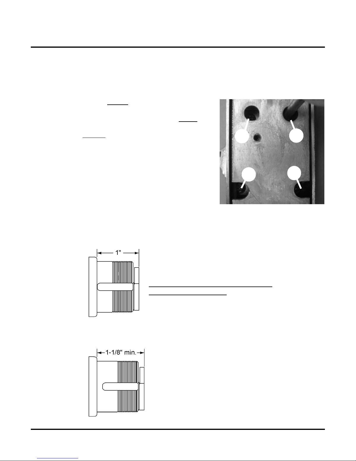
2) A Key Cylinder That Is At Least 1-1/8” Long Must Be Installed:
> The key cylinder that you install must be 1-
>>>> Do not attempt to install a key cylinder that is shorter than 1-1/8”
> The two illustrations below show the difference between a 1” and a 1-1/8” key cylinder.
1” long key cylinder.
DO NOT ATTEMPT TO INSTALL A 1”
LONG KEY CYLINDER.
ong or longer.
b
57040-E Page 6 04-2007
1-1/8” long key cylinder
ONLY INSTALL A KEY CYLINDER
THAT IS AT LEAST 1-1/8” LONG.
KC9111/KC9111-2 & KC9321/KC9321-2 INSTALLATION
To i
o
p
Installing the KC9111/KC9111-2 or KC9321/KC9321-2
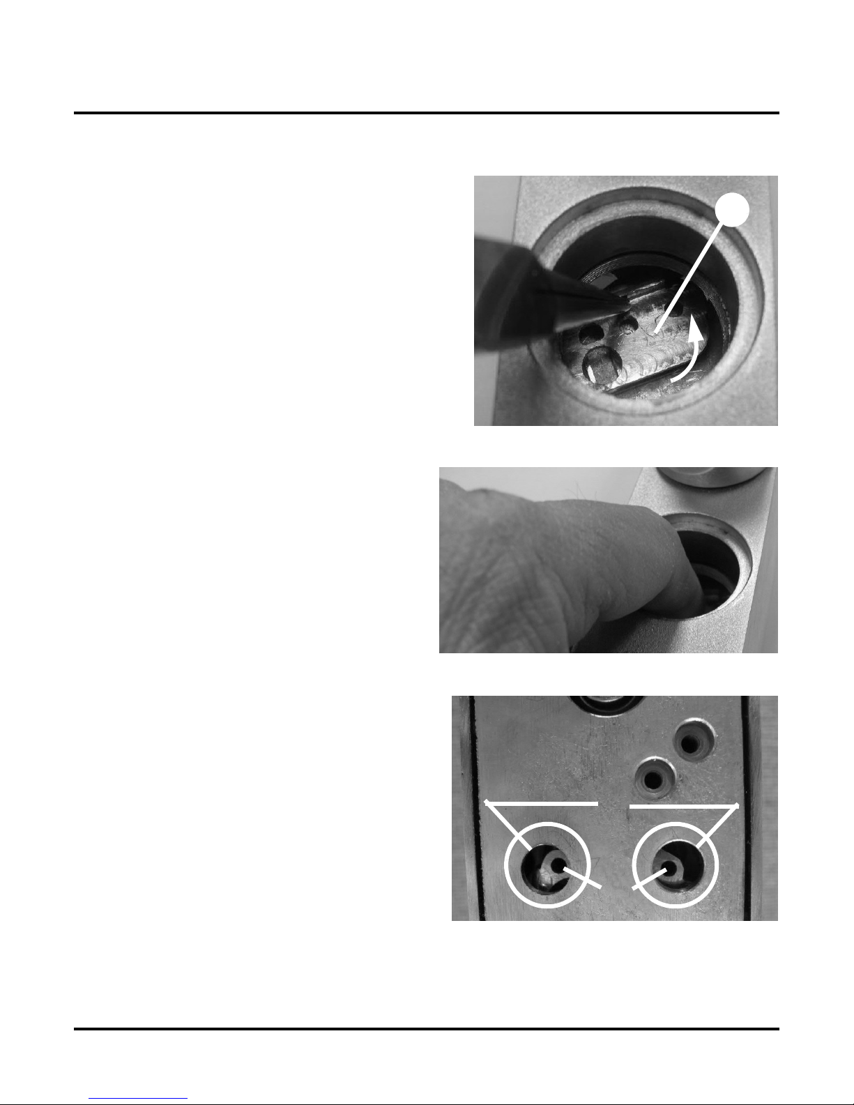
3) Make Room for Key Cylinder:
Due to the diameter of the key cylinder, it is necessary
to have dead latch (a) placed out of the way when
installing the key cylinder. Therefore...
• Using your finger or a pair of needle-nose
pliers, push dead latch towards the top end
of trim as indicated by arrow in photo.
NOTE: As indicated by arrow in photo, you’ll notice
that when you push the dead latch forward, it will
swing a little bit in a counterclockwise direction.
4) Hold Dead Latch in Place:
a
nsure that dead latch is placed far enough out
f the way to allow key cylinder to be threaded in
roperly:
• Insert a finger into key cylinder hole and
hold dead latch firmly in place.
• Carefully turn the trim over while keep-
ing the dead latch in position.
5) Verify Placement of Dead Latch:
Two holes on dead latch (a) should be showing within
the two holes (b) in baseplate.
Fig. 1
b
b
57040-E Page 7 04-2007
a
KC9111/KC9111-2 & KC9321/KC9321-2 INSTALLATION
ll .050”
Af
Installing the KC9111/KC9111-2 or KC9321/KC9321-2
6) Install the Key Cylinder:
• Insta
IMPORTANT: A .050” cylinder washer must be used IN ALL CASES,
regardless of the key cylinder length.
• If you are installing a cylinder that is longer than 1-1/8”, you
must also install a blocking ring (see Table 1: Blocking
Rings, on page 8).
A simple formula for determining blocking ring thickness is:
Blocking ring thickness = length of cylinder minus 1-1/8”
• If not already done, install cam onto cylinder. Cam must be clo-
ver leaf design (see Table 2: Recommended Cams, on page 8).
• Tilt top of trim down at a sharp angle.
• Screw in key cylinder until it stops. Use mechanical key as a han-
dle for turning if necessary.
cylinder washer.
Table 1: Blocking Rings
Key Cylinder Length Blocking Ring (Schlage P/N; XXX = finish)
• 1-1/4” 1/8” (36-079-012-XXX)
• 1-3/8” 1/4” (36-079-025-XXX)
• 1-1/2” 3/8” (36-079-037-XXX)
• 1-5/8” 1/2” (36-079-050-XXX)
Cylinder/Core Schlage Type Part Number
• Standard Mortise Cyl Everest L583-153
• Standard Mortise Cyl Classic L583-254
• Interchangeable Core IC Cam L583-255
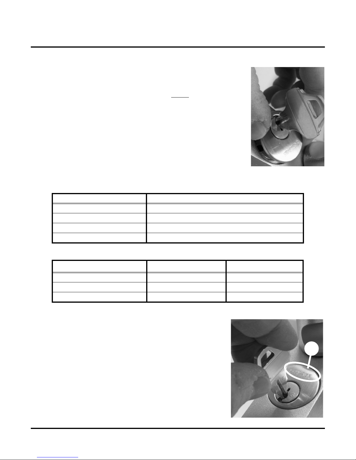
7) Align Key Cylinder:
•
ter screwing it all the way in, back off on key cylinder
(no more than one turn) until key is at the bottom. If key
cylinder has a logo (a), logo should be at the top of key
cylinder.
Table 2: Recommended Cams
a
57040-E Page 8 04-2007
KC9111/KC9111-2 & KC9321/KC9321-2 INSTALLATION
f
igh
lari
Installing the KC9111/KC9111-2 or KC9321/KC9321-2
8) Alignment of Interchangeable Cores:
• I
an IC Core is used, center the interface toward the
bottom.
9) Tighten the Four Screws in the Baseplate:
• T
10) The Dead Latch’s “Critical Edge:”
• For c
• Edge (a) is referred to as the dead latch’s
IMPORTANT: In the next step, the “critical
edge” on deadlatch will have to be lined up with
hole (b) in baseplate. See Position the Dead
Latch’s Set Screw Hole: on page 10
ten the four baseplate screws in the following order:
> Tighten a and b until snug.
> Tighten c and d until snug.
> Fully tighten a and b.
> Fully tighten c and d.
> Check all four screws to make sure that
all four are completely tight.
ty purposes only, photo on the
right is a view of deadlatch with escutcheon removed.
“critical edge.”
c
a
d
b
b
a
57040-E Page 9 04-2007
 Loading...