

Schlage KC9354,KING COBRA-2,KC9354-2,KING COBRA Installation Manual
KING COBRA/KING COBRA-2
NARROW STILE SERIES
KC9354/KC9354-2
Keypad Programmable
and SNAP Compatible Trim
For Narrow Stile Doors
57049-A 04-2007
KC9354/KC9354-2 INSTALLATION INSTRUCTIONS
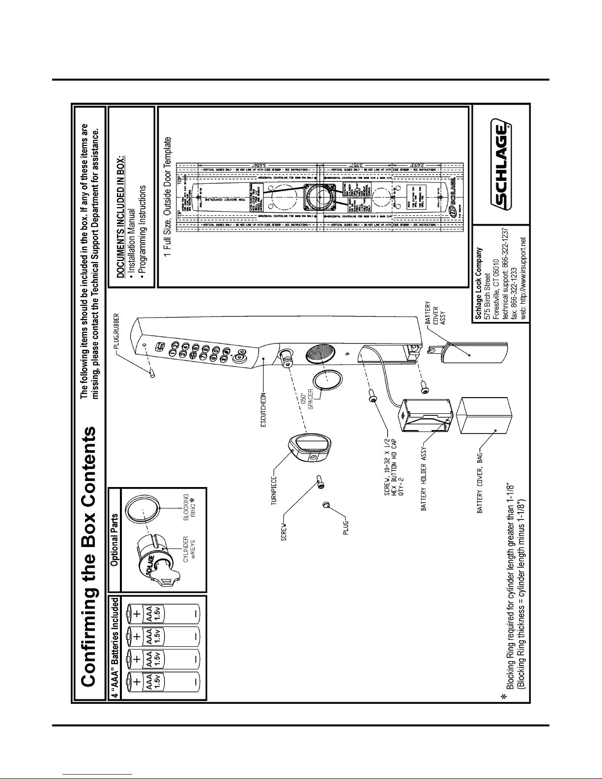
Contents of the Box
KC9354/KC9354-2 INSTALLATION INSTRUCTIONS
Contents of the BoxContents of the Box
57049-A Page 2 04-2007

KC9354/KC9354-2 INSTALLATION INSTRUCTIONS
1
1/8” wide blad
Introduction / Tools and Materials Needed / Contact Info
Introduction / Tools and Materials Needed / Contact Info
Introduction:
The KC9354/KC9354-2 will allow access by allowing the trim to unlock the exit
device when an access code or iButton is entered and the turnpiece is turned counterclockwise. Mechanical key override is standard. The trim is compatible with the
dogging features available with the Adams Rite® exit devices.
The KC9354/KC9354-2 is compatible with Adams Rite® 8600 concealed vertical rod exit devices and 4780 Series 2-point deadlatches w/paddle on aluminum doors.
Tools and Materials Needed:
.Flat head screwdriver w/straight,
2. Small Philips head screwdriver
3. 1/16” Allen wrench
4. Long nose needle-nose pliers
5. Center punch
6. Hammer
7. Power drill
8. 19/32” drill bit
9. 1/4” drill bit
10. Jig saw w/blade
11. Drill & Tap for 10-32 threads
e
Contact Information:
57049-A Page 3 04-2007
Schlage Lock Company
575 Birch Street
Forestville, CT 06010
technical support: 866-322-1237
fax: 866-322-1233
web: http://www.irsupport.net

KC9354/KC9354-2 INSTALLATION INSTRUCTIONS
Door Preparation
Door Preparation
Door Conditions:
Installation may require the use of a cover plate (a) to cover the holes left in the door.
If an existing pull (b) must be removed, Ives offers a compatible pull.
>Schlage Cover Plate P/N: KC9000-KRP
>Ives Pull P/N: 8190-18-xxx (xxx = finish)
Backset is determined by
the Adams Rite® lock.
b
Horizontal centerline for
Adams Rite® 8600 Rim
For factory prepped doors, use dimensions
shown. Dimensions are referenced from center of 1-1/4” cylinder hole. Backset is determined by the Adams Rite® lock.
When installing new Adams Rite® locks,
do not install outside cylinder (because this
trim replaces it).
a
(6.656”)
(3.957”)
(2.693”)
57049-A Page 4 04-2007
KC9354/KC9354-2 INSTALLATION INSTRUCTIONS
C9000
108
016
C9000
1/8”
N
Cams, Cores, Cylinders and Blocking Rings
Cams, Cores, Cylinders and Blocking Rings
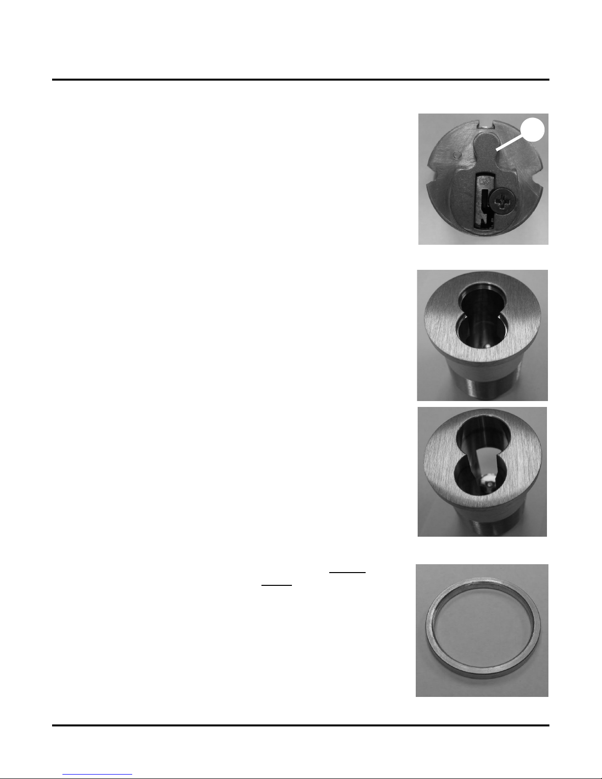
Cams For Mechanical Override Cylinder:
The K
is a list of compatible Schlage parts. For other manufacturers,
consult cross-reference charts.
> Cam for Standard Mortise cylinder: Schlage Everest: L583-153
Schlage Classic: L583-254
> Cam for Interchangeable Core: Schlage IC Cam: L583-255
trim requires the use of a clover leaf cam (a). This
IC Cores:
> Small Format IC core w/ cam: Schlage: 80-
NOTE: This core requires the use of 1/4” blocking ring:
Schlage: 36-079-025-<FINISH>
-<FINISH>
a
> Full Size IC core w/ cam: Schlage: 30-
NOTE: This core requires the use of 3/8” blocking ring:
Schlage: 36-079-037-<FINISH>
-<FINISH>
Cylinders / Blocking Rings:
The K
of a blocking ring. For cylinders longer
ring is required. The blocking ring thickness is equal to the cylinder length, minus 1-1/8”. For example, if you use a 1-1/2” cylinder you need a 3/8” blocking ring. Compression rings can be
ordered from a Schlage distributor:
Thickness: Schlage Part Number:
o compression ring: 1/8” 36-079-012-<FINISH>
1/4” 36-079-025-<FINISH>
3/8” 36-079-037-<FINISH>
1/2” 36-079-050-<FINISH>
can use a 1-
mortise cylinder without the use
than 1-1/8” a blocking
57049-A Page 5 04-2007
KC9354/KC9354-2 INSTALLATION INSTRUCTIONS
1/8” l
Installing the KC9354/KC9354-2
Installing the KC9354/KC9354-2
Installing the KC9354/KC9354-2
If your trim has a key cylinder already installed, skip to Determine Hand: on page 12. Otherwise, continue with Loosen the Baseplate Screws: on this page.
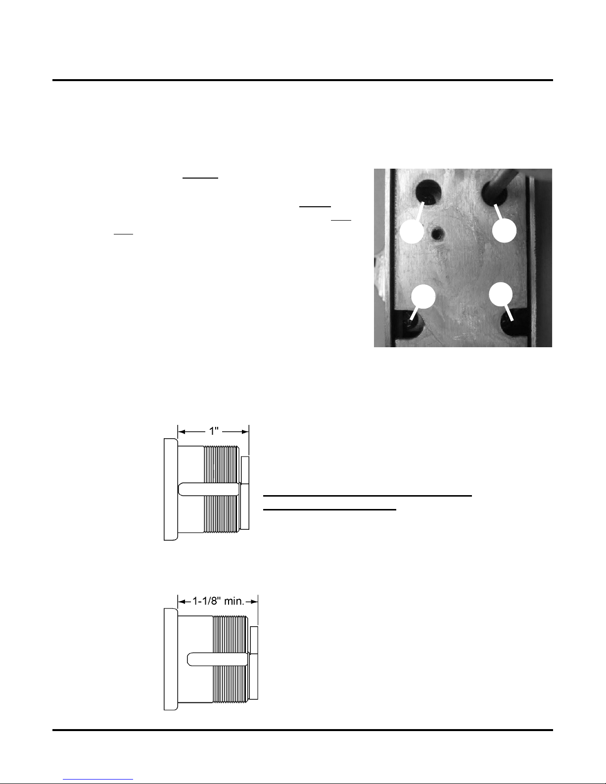
1) Loosen the Baseplate Screws:
IMPORTANT: Do not remove any of the screws in the following step or it will be difficult to reinstall them.
• Using a small Philips head screwdriver, loosen screws
a & b in baseplate, around key cylinder hole, one
turn.
NOTE: Screws a, b, c & d are set at the factory.
Screws a & b are tightened and screws c & d are left loose.
c
d
a
2) A Key Cylinder That Is At Least 1-1/8” Long Must Be Installed:
> The key cylinder that you install must be 1-
>>>> Do not attempt to install a key cylinder that is shorter than 1-1/8”
> The two photos below illustrate the difference between a 1” and a 1-1/8” key cylinder.
1” long key cylinder.
DO NOT ATTEMPT TO INSTALL A 1”
LONG KEY CYLINDER.
ong or longer.
b
57049-A Page 6 04-2007
1-1/8” long key cylinder
ONLY INSTALL A KEY CYLINDER THAT IS AT LEAST 1-1/8”
 Loading...