

Schlage CM5500-IBO,CM5500-MGK,CM5500-MGI,CM5500,CM5500-KPI,CM5500-PXK,CM5500-PXI,CM5598,PRO5500 Installation Manual

CM5500 COMPUTER MANAGED MORTISE LOCK
The 5500 series lock is a stand-alone, microprocessor controlled, electromechanical locking system. The 5500 employs a heavy-duty mechanical design with fewer
moving parts that a standard mechanical mortise lockset, for ease of installation
and high reliability. It is powered by four, standard AA batteries, providing up to
80,000 activations.
Operationally, the outside lever is normally locked and the inside lever always
retracts the bolt to allow egress. Electronic access control is achieved by entering
an”Access Credential” (magnetic stripe card, code of iButton Key, or HID Prox fob
or card). Electronic access control capabilities are listed below by model. All models are designed to accommodate an emergency mechanical key override.
Standard features of the CM models include up to 1000 user memory, real time
features including time zones and holidays, and audit trail of up to 1000 events.
Optional ATK (audit trail - key override) will note any use of the mechanical key on
the audit trail report. Manual and computer programming is supported by all models. The PRO models are manually programmed to accept up to 100 codes.
Functions:
5590: Office Function (3/4” latch) - has “Lock” and “Unlock” buttons on inside
escutcheon. Function not available on PRO
5596: Storeroom/Classroom Function (3/4” latch) - can be unlocked by “toggle”
credential and relocked again by same. See programming guide for more information (form 57000).
5598: Classroom Function with inside iButton reader - can be toggled unlocked by
iButton plus pin (code). Can be relocked immediately from inside iButton reader in
an emergency.
5591: Office Function (1” Autobolt) - has “Lock” and “Unlock” buttons on inside
escutcheon. Function not available on PRO
5594: Storeroom/Classroom Function (1” Autobolt) - can be unlocked by “toggle”
credential and relocked again by same. See programming guide for more information (form 57000). Function not available on PRO
5593: Dormitory/Privacy Function (1” Autobolt) - Pushing either button on the
inside escutcheon places lock in the “Privacy” mode: a “Lockout” credential or
mechanical key is required to enter. Condition is cleared when the bolt is retracted
from the inside. Function not available on PRO
INSTALLATION MANUAL
CM5500-KPI CM5500-IBO
CM5500-MGK CM5500-MGI
Models:
KPI: iButton reader and keypad
IBO: iButton reader only
MGK: Magnetic stripe card reader, iButton reader and keypad
MGI: Magnetic stripe card reader and iButton reader
PXK: Prox card reader, iButton reader, and keypad
PXI: Prox card reader and iButton reader
PRO: Keypad only - Manual programming only, 100 code memory
Options:
ATK: Audit trail of mechanical
key use (not available on PRO)
HSS: High security screws on
inside escutcheon
T3: Track 3 card reader
(data must be ABA track 2 format) - MGI/MGK only
KD: Keyed Different, includes
Schlage Everest cylinder
LC: Less Cylinder
Form 55005 Rev. B
5500 MORTISE LOCK
STANDARD
5500 MORTISE LOCK
AUTOBOLT
CM5500-PXK CM5500-PXI
CM5598
SAFE SCHOOL LOCK
WITH iBUTTON
READER ON INSIDE
PRO5500
09-25-2001

CM5500 COMPUTER MANAGED MORTISE LOCK
INSTALLATION MANUAL
BEFORE YOU BEGIN:
Standard units are shipped from the factory to fit 1-3/4” doors. Verify the door thickness. If the door is not 1-3/4” thick, verify
that the door thickness option was ordered or consult factory.
1. PREP DOOR AND FRAME (IF NOT ALREADY DONE):
A. Determine door hand.
B. Mark the horizontal and vertical centerlines for the lock case (on door edge), strike, lever, and inside escutcheon. Note
that the backset is actually 2.813” (or 2 13/16”). This is very important for proper mounting.
C. Place template on inside of door (opposite the side that the keypad/reader will be on). Line up the correct reference lines
on the template with the edge of the door, depending on the hand (see paper template). The centerline on the door should
line up with the vertical centerline of the template. Use the paper template to mark all holes. (Though the paper template is
the preferred way to prep the door, the dimensions below may be used if a paper template is not available.)
D. Drill required holes. Note that all holes are required except the 3/4” hole just below the 1” hole, this is only required if the
lock has the privacy feature (model 5594).
Form 55005 Rev. B
09-25-20012
CM5500 COMPUTER MANAGED MORTISE LOCK
INSTALLATION MANUAL
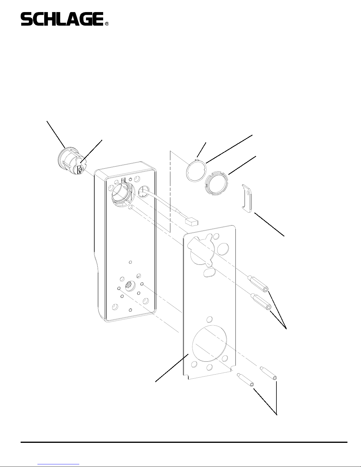
2. INSTALL CYLINDER, GASKET AND STANDOFFS:
A. Install cam onto cylinder. Cam can be either a cloverleaf (shown) or straight, 11/16” design (not shown).
B. Insert standard, 1-1/4” mortise cylinder into outside escutcheon from front (keypad/reader) side with keyway down.
C. Slide lock washer into place with tab on top facing out, as shown below.
D. Using nut tool (provided) tighten nut onto cylinder.
E. Line up nearest notch on nut with tab on lock washer and bend tab into notch using nut tool so nut is secure.
F. Install exterior gasket (if used).
G. Install upper and lower standoffs.
CYLINDER
RECOMMENDED CAM:
SCHLAGE P/N B502-948
TAB
LOCK WASHER
NUT
EXTERIOR GASKET
NUT TOOL
STANDOFFS - UPPER
Form 55005 Rev. B
STANDOFFS - LOWER
09-25-20013
 Loading...