

Schlage CM5100-FSE-MGK, CM5100-FSE-KPI, CM5100-FSE-IBO, CM5100-FSA-MGK, CM5100-FSA-MGI Installation Manual
...
CM5100 COMPUTER MANAGED CYLINDRICAL LOCK
HARD-WIRED (FSE/FSA) INSTALLATION MANUAL
The 5100 series lock is a stand-alone, microprocessor controlled, electromechanical locking system. The 5100 employs a heavy-duty mechanical
design which is easy to install and highly reliable. The FSE and FSA solenoid-driven models are hard-wired to a 12 or 24 volt (AC or DC) power
supply. They offer fail secure and fail safe operation,
respectively.Operationally, the outside lever is normally locked and the
inside lever is always free to allow egress. Electronic access control is
achieved by entering an ”Access Credential” (magnetic stripe card, code,
iButton Key, or HID Prox fob or card). Electronic access control capabilities
are listed below by model. All models are designed to accommodate an
emergency mechanical key override. Standard features of the CM models
include up to 1000 user memory, real time features including time zones
and holidays, and audit trail of up to 1000 events. Optional ATK (audit trail
- key override) will note any use of the mechanical key on the audit trail
report. Manual and computer programming is supported by all models
which have a keypad. The PRO models are manually programmed to
accept up to 100 codes.
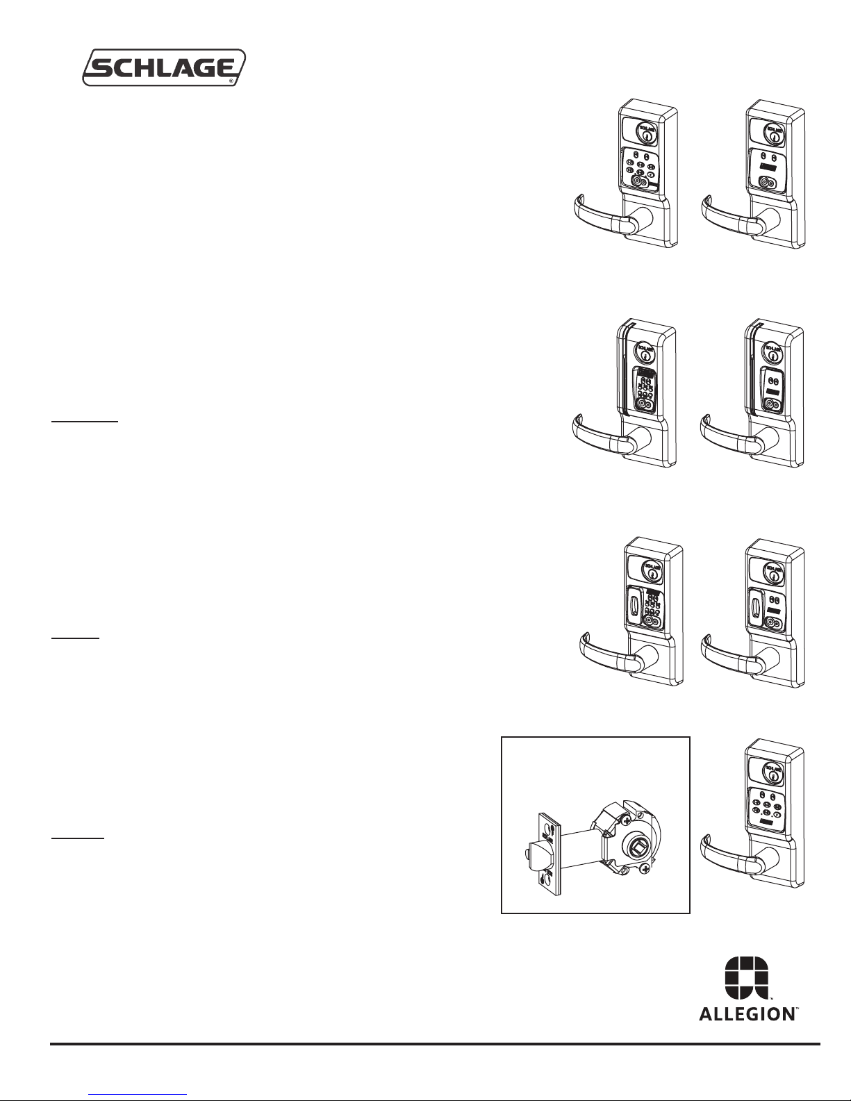
CM5100-FSA-KPI
CM5100-FSE-KPI
CM5100-FSA-IBO
CM5100-FSE-IBO
Functions
5190: Office Function - has “Lock” and “Unlock” buttons on inside
escutcheon - function not available on PRO
5195: Dormitory/Privacy Function - Pushing the “PRIVACY ON” button on
the inside escutcheon places lock in the “Privacy” mode: a “Lockout” credential or mechanical key is required to enter. Condition is cleared when
the door is opened. Function not available on PRO
5196: Storeroom/Classroom Function - can be unlocked by “toggle” credential and relocked again by same. See programming guide for more
information.
Models
FSA: Solenoid operated clutch - fail safe
FSE: Solenoid operated clutch - fail secure
KPI: iButton reader and keypad
IBO: iButton reader only
MGK: Magnetic stripe card reader, iButton reader and keypad
MGI: Magnetic stripe card reader and iButton reader
PXK: Prox card reader, iButton reader, and keypad
PXI: Prox card reader and iButton reader
PRO: Keypad only - no computer programming, 100 code memory
:
:
CM5100-FSA-MGK
CM5100-FSE-MGK
CM5100-FSA-PXK
CM5100-FSE-PXK
5100 CYLINDRICAL
LOCKSET - STANDARD
CM5100-FSA-MGI
CM5100-FSE-MGI
CM5100-FSA-PXI
CM5100-FSE-PXI
Options:
ATK: Audit trail of mechanical key use (not available on PRO)
HSS: High security screws on inside escutcheon
SLB: 2-3/4” backset, 1/2” latch bolt
OLB: 2-3/8” backset, 1/2” latch bolt
ELB: 2-3/4” backset, 3/4” latch bolt
T3: Track 3 card reader (data on track 3 must be ABA track 2 format)
- MGI/MGK only
KD: Keyed Different, includes Schlage Everest cylinder
LC: Less Cylinder
Form 51116-C
PRO5100-FSA
PRO5100-FSE
CM5100 COMPUTER MANAGED CYLINDRICAL LOCK
HARD-WIRED (FSE/FSA) INSTALLATION MANUAL
BEFORE YOU BEGIN:
Standard units are shipped from the factory to fit 1-3/4” doors. Verify the door thickness. If the door is not 1-3/4” thick, verify
that the door thickness option was ordered or consult factory. Hard-wired units (FSE & FSA models) will require that wiring
is brought to the door prep. In step 1, “PREP DOOR AND FRAME”, there are some suggested ways of doing this. A door
cord, electric hinge or some other form of wire transfer device will be required.
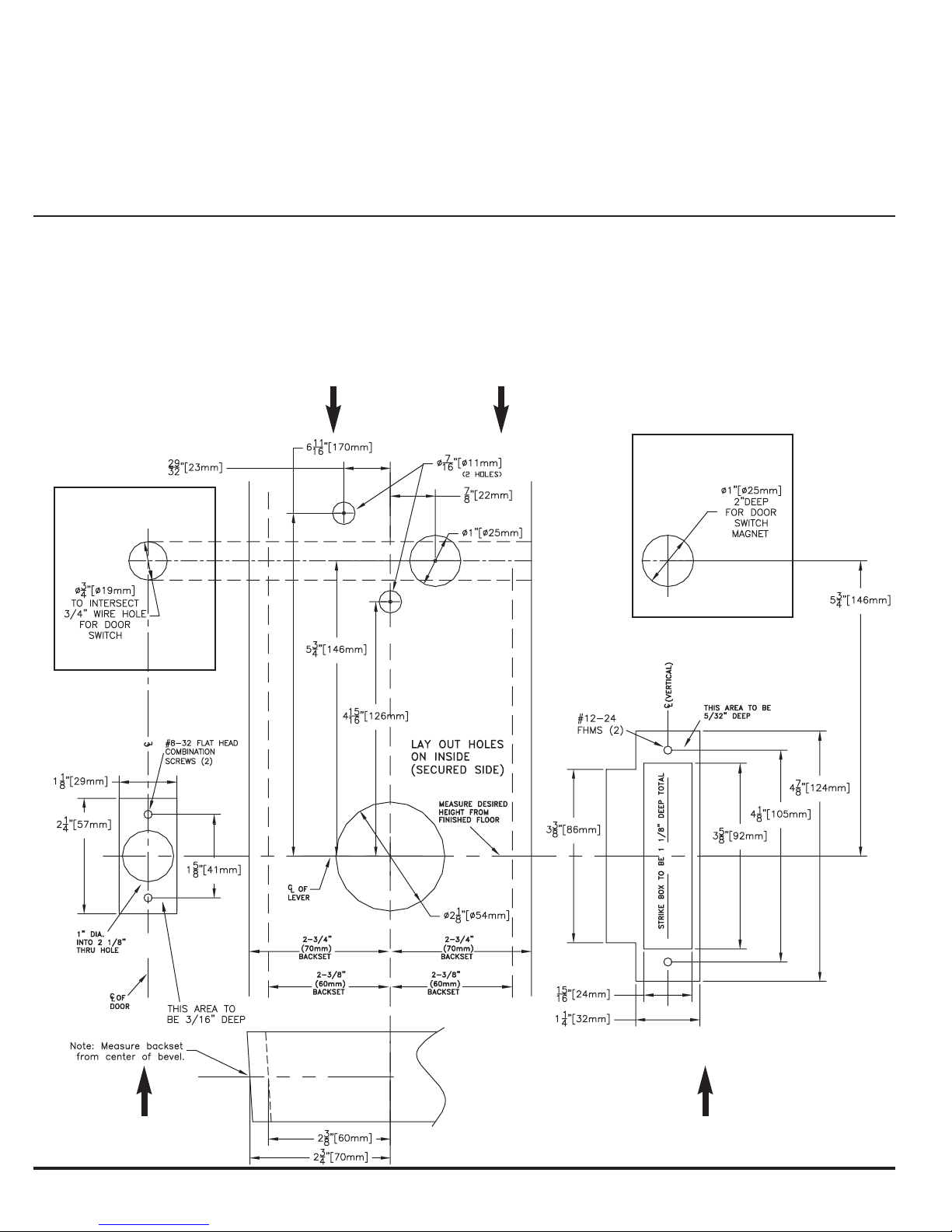
1. PREP DOOR AND FRAME:
A. Determine door hand and correct backset.
B. Mark the horizontal and vertical centerlines for the lockset, latch and strike.
C. Place template on inside of door (opposite the side that the keypad/reader will be on). Line up the correct reference lines
on the template with the edge of the door. The centerline on the door should line up with the vertical centerline of the template.
D. Drill holes as described by template.
DOOR FACE (LAY OUT ON INSIDE)
CM5195 ONLY
(PRIVACY FUNCTION)
CM5195 ONLY
(PRIVACY FUNCTION)
DOOR EDGE (LATCH)
Form 51116-C
FRAME (STRIKE)
2
CM5100 COMPUTER MANAGED CYLINDRICAL LOCK
HARD-WIRED (FSE/FSA) INSTALLATION MANUAL
FSE & FSA MODELS:
It is best to have the wire race way prepared at the door and
frame manufacturer. If this has not been done there are two
suggested preparation methods for making wire paths for the
FSE and FSA models in the field. Depending on the door and
frame circumstances, one may be better than the other. Consult
door manufacturer with any questions regarding agency listings
with respect to fire integrity.
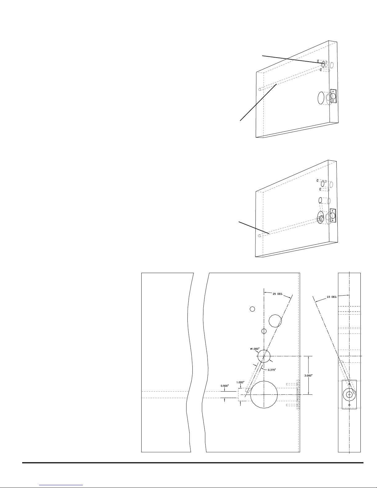
METHOD A:
1. Prep door and frame according to standard template.
2. Determine location of standard 1 inch wire harness through
hole and mark centerline of hole on hinge side of door.
3. Using appropriate drilling jig and drill bits, drill 3/8” or 1/2”
wire race from edge of hinge side into standard wire harness
through hole.
4. Install electric hinge or door cord and run wires.
METHOD B:
1. Prep door and frame according to standard template.
2. Using a 1” drill bit, continue the 1” latch hole through retractor
hole to a depth of 5”. This will allow room for the wiring to pass
around the retractor.
3. Using appropriate drilling jig and drill bits, drill 3/8” or 1/2”
wire race from the latch hole through the door toward the hinge
side. It is not be necessary to continue the hole through the
hinge side.
4. Measure up 3 inches from the center of the 2 1/8” retractor
hole and drill a 1 inch through hole on center as shown below.
5. Using a 3/8 inch drill bit, place the tip of the drill into the 1”
wire hole drilled in step 3 and aim at the angles shown. Drill
down and toward the hinge side to intersect the 1” latch hole
(where it was continued in step 2.
4. Install electric hinge or door cord and
run wires.
Note: this method offers the advantage of
not having holes exiting the door edges.
If a door cord is used the door cord wire
hole can be cross drilled into the long
wire race.
STANDARD WIRE
HARNESS THROUGH
HOLE
METHOD A:
WIRE RACE
METHOD B:
WIRE RACE
HARD WIRED LOCKS RATED AT:
0.5 AMPS @ 12 VDC
0.5 AMPS @ 12 VAC
0.5 AMPS @ 24 VDC
0.5 AMPS @ 24 VAC
Form 51116-C
3
 Loading...