

Page 1
1
-
Page 2
2
Уважаемый покупатель!
Спасибо за выбор продукции Schaub Lorenz! Мы уверены, что приобретённая Вами вытяжка
удовлетворит Ваши потребности и прослужит Вам долгие годы . Для обеспечения надёжной и
эффективной работы вытяжки , а также Вашей безопасности внимательно ознакомьтесь с
настоящим руководством по эксплуатации .
Не выбрасывайте руководство, сохраните его для того, чтобы всегда можно было к нему обратиться.
Раздел 1 Меры предосторожности
Раздел 2 Технические характеристики
Раздел 3 Размеры
Раздел 4 Схема электрического соединения
Раздел 5 Установка вытяжки
Раздел 6 Управление
Раздел 7 Обслуживание, Замена фильтров
Раздел 1 Мер ы предосторо жно сти – Безопасн ос ть .
Установка, сборка и электрическое подключение вытяжки должны осуществлять компетентные лица
или представители сервисного центра . Данная вытяжка предназначена для использования в
домашних условиях.
Устройство включается в сеть с переменным электрическим напряжением 220-230В и заземлением
Используйте вытяжку по назначению, во избежание возможных поломок.
Питание вытяжек не может быть подключено в одну розетку совместно с другими мощными
электроприборами. Одновременная работа вытяжки и других мощных электроприборов может
быть причиной поломки.
Вытяжка монтируется не ниже 5 см, над духовкой и не ниже 75 см над варочной поверхностью,
работающей на газе или смешанном топливе.
При установке избегайте натяжения или заломов кабеля питания.
Не готовьте пищу, которая может воспламениться под вытяжкой.
Используйте только стандартные фильтры.
Если сверлите стену следите за тем, чтобы не повредить электропроводку или другие спрятанные
провода.
Не проверяйте состояние фильтра, в рабочем режиме.
Не открывайте газ, если на плите нет посуды это может повредить фильтр и стать причиной пожара.
Page 3
3
Вовремя промывайте фильтры, равно как и вовремя осуществляйте замену угольных фильтров.
Длина
600-900 мм
Ширина
475 мм
Высота
Мин. 706 мм. / Макс. 980 мм. (в
зависимости от конфигурации
приобретенной Вами модели)
Панель управления
Механическое / Сенсорное (в
зависимости от конфигурации
приобретенной Вами модели)
Производительность,(M³/H)
От 600 до 800 м3 (в зависимости
от конфигурации приобретенной
Вами модели). См. шильдик на
приборе.
Мощность лампы (Вт)
2x15 Вт.; 2x28 Вт.; 2x1 Вт.
Мощность, двигателя
110 – 190 Вт.
Мощность, (Вт)
140- 220 Вт.
Диаметр Вых. Отверстия
120 мм
Напряжение, (Вольт)
220 – 240 V 50Hz
a.
Несоблюдение этой рекомендации может стать причиной воспламенения фильтра, на котором
аккумулируется значительное количество жиров.
Если вы обнаружили повреждение кабеля питания – необходима его замена, которая должна
производиться представителем сервисного центра.
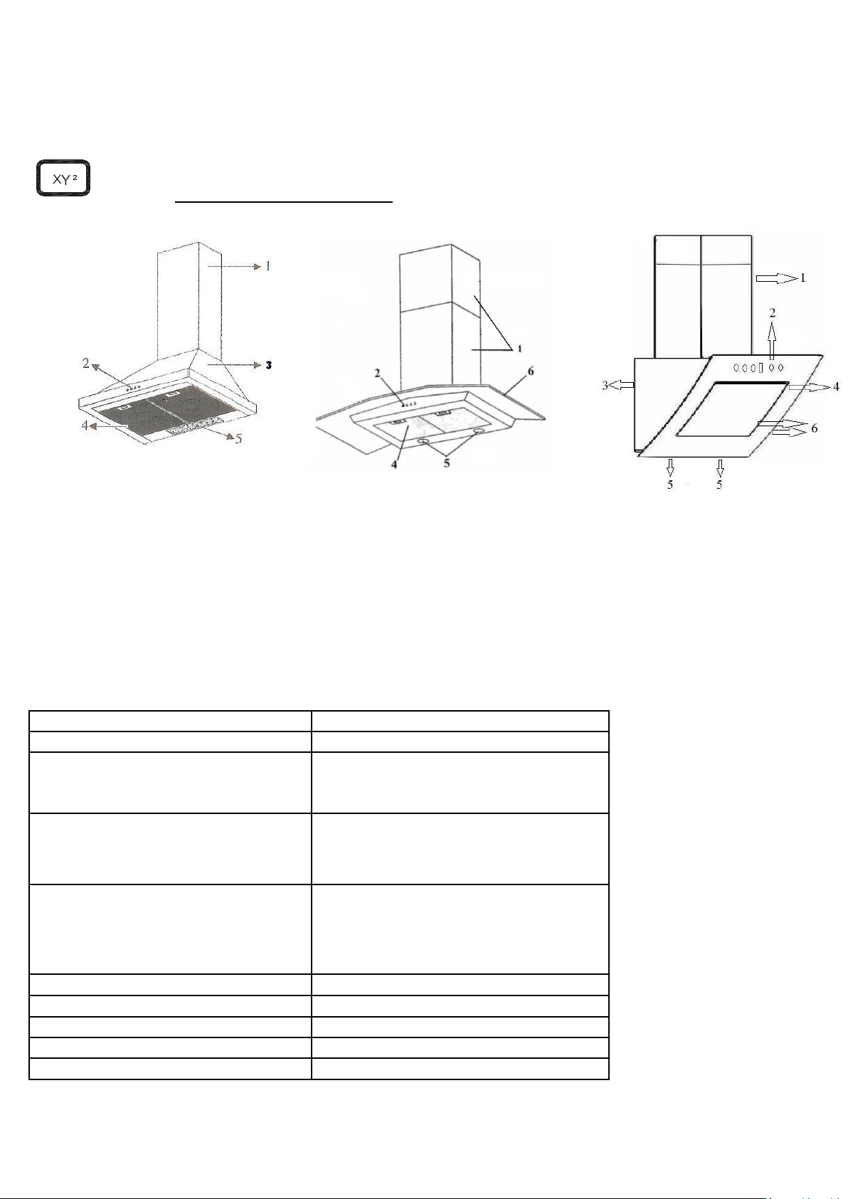
Раздел 2 Технические характеристики
1. Дымоход:
2. Контрольная панель
3. Металлический корпус
4. Алюминиевые фильтры
5. Лампа подсветки
6. Стекло (Фронтальное)
6a. Стекло декоративное (верхнее)
Таблица: Технические характеристики вытяжки
Page 4
4
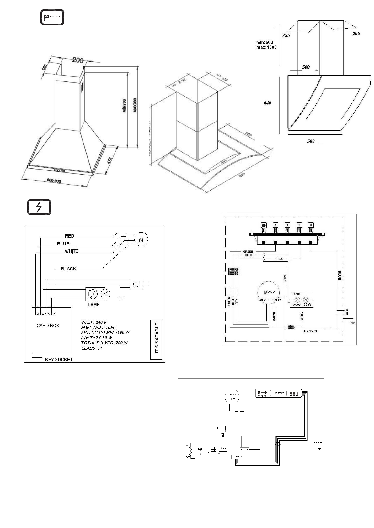
Раздел 3 Технические Размеры (Примечание: Все
Раздел 4 Схема электрического соединение
размеры указаны в мм.)
Сенсорные Управление
Кнопочное Управление
ЛСД
Управление
Page 5

5
Page 6
6
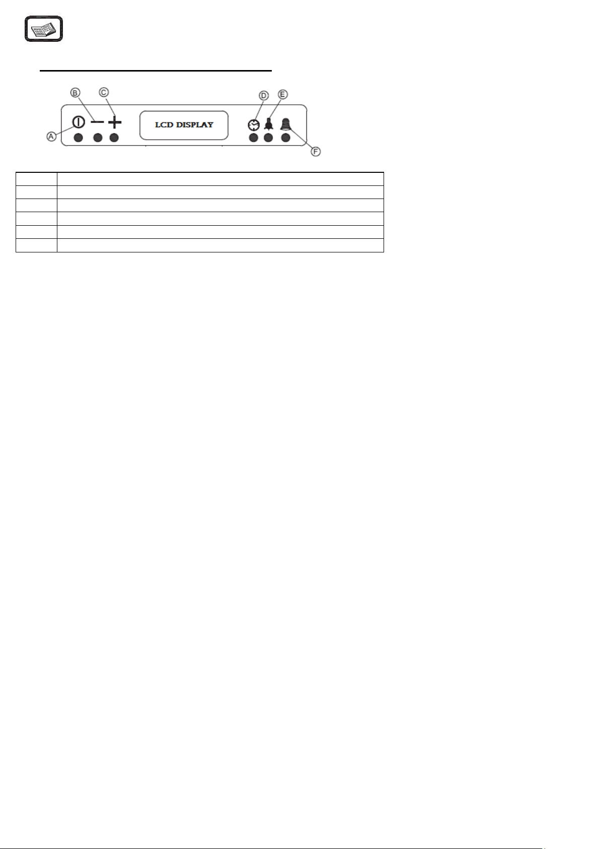
A
Кнопка ВКЛ/ВЫКЛ
B
Кнопка М И Н У С
C
Кнопка П Л Ю С
D
ТАЙМЕР
E
Кнопка освещения
F
Кнопка СИГНАЛА
Раздел 6 Управление
LCD - жи дкокри сталли ческий ди сп лей
M.on/ off Кнопка : Применяется для остановки или включения двигателя. Двигатель сначала работает во 2-
м режиме. Число оборотов отображается на экране бар ступенями и скоростью оборотов вентилятора.
Кнопка минус: При каждом нажатии на данную кнопку во время работы двигателя, скорость двигателя
будет уменьшаться до 1-й ступени. На экране уменьшатся единица давления бар и снижается скорость
оборотов вентилятора .
Кнопка плюс: При каждом нажатии на данную кнопку во время работы двигателя, скорость двигателя
будет увеличиваться до самой высокой ступени . На экране увеличится единица давления бар и скорость
оборотов вентилятора. Максимальный режим данной момент модели 3-й. На ЛСД в 3-м режиме загорятся
три деления.
Кнопка отключения таймера: При нажатии на кнопку отключения таймера, во время работы двигателя, на
экране будут показаны заводские показатели начальной установки 15 - минутного таймера и появится
пятикратное мигание изображения часов. Изображение часов будет на экране до окончания
установленного времени электронного таймера . По окончании работы электронного таймера двигатель
остановится , и, если лампа подсветки включена , то таймер также её отключит.
Кнопка сигнала таймера: При нажатии на эту кнопку, независимо от работы двигателя, на экране появятся
показатели начальной величины установки 5-минутного таймера и появится пятикратное мигание
индикатора сигнала . Изображение будет на экране до окончания установки электронного таймера. По
окончании работы таймера , в течение 20 секунд зуммер будет подавать сигнал и индикатор сигнала
зажжется. Нажав на сигнальную кнопку, произведите выключение сигнала зуммера.
Действительно для любых режимов работы таймера: При однократном нажатии во время мигания на
кнопку МИНУС или ПЛЮС возможна регулировка времени таймера от 1 минуты до 9 часов 59 минут. При
длительном нажатии на кнопку МИНУС или ПЛЮС время на таймере будет резко увеличиваться или
уменьшаться. При нажатии кнопки таймера при настроенном таймере на экране появится настроенное
время на данный момент. Для обнуления настроек таймера необходимо нажать на кнопку запуска таймера
и потом удерживать кнопку МИНУС до сброса на нуль.
Кнопка подсветки : Включает и выключает лампы подсветки. При включенных лампах на правой стороне
экрана загорается изображение лампы.
Предупреждение необходимости очистки фильтра: После 60 часов работы вытяжки на экране появится
надпись, предупреждающая о необходимости очистки фильтра (CLEAN FILTER). При нажатии и удерживании
Page 7

7
кнопки M.on/ off в течение 4 секунд будет слышен звуковой сигнал и появится надпись (CLEAN FILTER),
которая также отобразится на экране в течение 1,5 секунды.
Power OFF: В момент отключения электрического питания нужно нажать кнопку Power ON, на экране
появится индикация времени и LCD индикатор вытяжки будет продолжать работать в режиме обычных
часов.
Настройка часов : Нажать одновременно на кнопки МИНУС И ПЛЮС и войти в режим настройки времени.
Во время настройки часов на экране в середине часов будет мигать треугольный значок. Кнопками МИНУС и
ПЛЮС выполняется настройка часов. Если случайно будет нажата другая кнопка помимо МИНУС и ПЛЮС, то
осуществится выход из настройки часов.
СЕНСОРНАЯ ПАНЕЛЬ УПРАВЛЕНИЯ
1. включение/выключение вытяжки
2. LED дисплей, показывающий скорость работы вытяжки
3. уменьшение скорости
4. увеличение скорости
5. функция «автономный режим»
6. включение/выключение освещения
1. включение/выключение вытяжки
2. увеличение скорости
3. уменьшение скорости
4. включение/выключение освещения
Page 8

8
Auto-Hood сенсорную панель управления
Фильтры и инструкция по их очистке.
Алюминиевый фильтр: На алюминиевом фильтре после длительной работы вытяжки остаются жир и пыль.
Данный фильтр необходимо мыть раз в месяц теплой мыльной водой, либо в посудомоечной машине при
температуре 60 ˚С. Для того чтобы снять фильтр, необходимо надавить и отодвинуть фиксаторы. Не используйте
помытый фильтр до тех пор , пока он полностью не высохнет.
Угольный фильтр: Угольный фильтр удаляет неприятный запах из воздуха. Его замена производится каждые три
месяца. Угольный фильтр не моется.
Очистка фильтров и корпуса вытяжки : Перед чисткой алюминиевого фильтра вытяжки или заменой угольного
фильтра отсоедините вытяжку от электрической сети . Внешнюю часть вытяжки можно очищать жидким моющим
средством . Для очистки деталей из нержавеющей стали используйте средства для чистки металлических
поверхностей – они хорошо удаляют загрязнения и отпечатки пальцев. Однако при использовании подобных средств
необходимо помнить, что некоторые средства могут вызывать аллергию и раздражение. Избегайте попадания
средств для очистки в глаза и на кожу, если же это случилось – промойте глаза водой и обратитесь к доктору, кожу
также необходимо промыть проточной водой с мылом. Для очистки поверхности вытяжки и алюминивого фильтра
не используйте кислоту и металлическую мочалку. Во время очистки вода не должна попасть в двигатель и на
другие электрические части и модули.
Замена ламп подсветки .
1. включение вытяжки, уменьшение/ увеличение скорости
2. включение/выключение освещения
3. функция «автономный режим»
4. LED дисплей, показывающий скорость работы вытяжки
5. Датчик - сенсор (sensor)
6. открыть стекло
7. выключение вытяжки
Раздел 7 Обслуживание, Замена фильтров
Отключите электропитание вытяжки.
Снимите алюминиевый фильтр.
Замените перегоревшую лампу на новую.
Page 9

9
Возможные неполадки и их устранение
Проверьте
подключение
к
электрос
ети
(
напр
яжение
должно быть 220 В , розетка должна быть с заземлением)
Проверьте
на пнели управл
ения
режим
включения двигат
еля
Проверьте
режим включения
ламп
подсветки
Проверьте
степе
нь загрязнения
алюм
иниевого
фил
ьтра
Проверьте
лампоч
ки, они мог
ли
перегор
еть
Проверьте
выхо
дное отверстие
вентиляционного
кана
ла (оно
должно быть откр
ыто)
Проверьте
сост
ояние уго
льного
фильтра
(где он предусм
отрен)
Уго
льный фильтр
необходимо
заменять каждые три месяца
Вытяжка не работает
х
Х
Не горят лампочки
х х Х
Слабая тяга
х
х
х
Нет обратного
выхода воздуха
х
х
Если вытяжка не работает, прежде чем обратиться в сервисный центр, убедитесь, что шнур питания включен в
розетку и не поврежден, а также проверьте по предоставленной выше таблице возможные неполадки и
предложенные пути их решения.
Если неполадку не удается устранить при помощи способов приведённых в таблице , не пытайтесь осуществлять
какой-либо ремонт самостоятельно – это может привести к выходу вытяжки из строя и отказе Вам в гарантийном
обслуживании , обязательно обратитесь в авторизованный сервисный центр.
Page 10

10
SCOPE OF INSTRUCTION MANUΑL
Dear Customer,
THANKS FOR CHOOSING OUR HOOD. In the sections provided here in, there is necessary information which will
enable you to use the device efficiently and safely. Please, read these instructions carefully before installation of
the device
Section 1 Important points which must be observed before using the chimney
Section 2 Technical specifications of the chimney hood.
Section 3 Technical dimensions of the chimney hood
Section 4 Electrical diagram of the chimney hood.
Section 5 Information about installation connection of the chimney hood.
EN
Section 6 Information about use of the chimney hood.
Section 7 Information about maintenance of the chimney hood.
IMPORTANT PRECAUTIONS AND POINTS WHICH MUST BE OBSERVED
THE DEVICE IS PRODUCED AS EARTHED.
DO NOT USE IT WITH UNEARTHED PLUG.
Section 1
1. The electrical and installation connections must be done by the service staff who is well-informed of the
subject;
2. The operating voltage is 220 – 240 Volts. Do not operate the device in lower or higher voltage.
3. Do not connect to the chimneys where the heating stove is connected, to the gas flue or to the chimneys
where the fire rises.
4. Plug the product into the socket where there is an earthed connection.
5. Fire catching food should not be cooked under the device.
6. Do not use other materials instead of aluminum filter in the device.
7. Do not plug into the socket without completion of the installation of the device.
8. Do not run the device without aluminum filter.
9. Do not touch the bulb of the device when it is left on for a long time
10. Do not remove the aluminum filter when the device is running.
11. Do not turn off the device directly by plugging it out when it is running. Turn it off from control panel.
12. The device should be cleaned periodically..
Page 11

11
EN
13. The height between the lower surface of the chimney hood and oven must be 65 cm for electrical ovens,
and 75 cm for gas-fired or mix ovens
14. Keep the packaging material away from the children because they may be dangerous for them.
15. Run the chimney hood after the kettle or frying pan is put on the oven.
16. Run the chimney hood for 15 minutes more after the operation of cooking or frying is finished in order to
clean the air of the kitchen off the smell and vapor which appeared during cooking..
17. Let some fresh air into environment when the chimney hood is running, especially, when it is used in the
same time with the gas-fired ovens.
18. Contact the nearest service if your device is failed to run with any reason.
19. Our Company may not be held responsible from the failures arising from use which is not consistent with
the cautions stated above.
20.
TECHNICAL SPECIFICATIONS
Section 2
1. Chimney
2. Control panel
3. Body of the chimney hood
4. Aluminum filter
5. Illumination lamp
6. Glass
Page 12

EN
11
LENGTH
600-900 mm
WIDTH
475 mm
HEIGHT
Min. 706 mm Max 980 mm
CONTROLLER
PUSH BUTTON, DIGITAL BUTON,
TOUCH CONTROL , LCD SCREEN
AIR SUCTION
600-800 m3
BULB POWER
2x15W; 2x28 W; 2x1W
MOTOR POWER
110 – 190 W
TOTAL POWER
140- 220 W
DIAMETER OF AIR OUTLET
PIPE
120 mm
SUPPLY VOLTAGE
220 – 240 V 50Hz
TECHNICAL SPECIFICATIONS OF THE CHIMNEY HOOD
TECHNICAL DIMENSIONS
Section 3
Note: All dimensions are in mm.
Page 13

EN
12
ELECTRICAL CONNECTION DIAGRAM
Section 4
Digital Touch Button Push Button
LCD Screen
INSTALLATION DIAGRAM
Section 5
Draw a straight line by a measuring stick starting from the surface of the oven to 700+280: 990 mm if you want to
save a space of 700 mm between the oven and the lower surface of the chimney hood. Align the drawn line to the
right and left edges. Draw a 67,5 mm axis line from aligned center to every two sides. Make a hole by 6 mm
diameter electrical drill through two drawn points. Penetrate the expansion bolt and install the hangers.
Doing installation of secondary chimney of the chimney hood: draw 75 mm line from the top surface towards the
lower section. Make sure that the line is equal to right and left parts. Draw 50 mm line each at both sides of the line
and, then, make a hole through these two lines. Penetrate an 8 mm diameter expansion bolt and tighten until 2 mm
space is left in-between of a 2,5 diameter slat screw and the expansion bolt. Later, the product is mounted on its
place and the installation will be completed by installing the inner chimney.
Page 14

EN
13
A
ON-OFF BUTTON
B
MINUS BUTTON
C
PLUS BUTTON
D
TIMER BUTTON
E
BULB BUTTON
F
ALARM BUTTON
The operation order:
st
1
operation: Installation of hanger
nd
2
operation: Installation of chimney connection metal sheet
rd
3
operation: Hanging the chimney hood
th
4
operation: Installation of lower chimney of the chimney hood
th
5
operation: Installation of inner chimney
th
6
operation: Making electrical connection
INSTALLATION :
INFORMATION ABOUT USE OF THE CHIMNEY HOOD
Section 6-1
LCD-Switch Chimney Hood Control Card Features
Page 15

14
On/Off Button: used to start and stop the motor. In the beginning, the motor runs in 2
nd
cycle. The number
of cycle is represented by bar levels and the rotation speed of the fan shown at the left-side of the display.
Minus Button: the cycle of motor reduces until it reaches 1
st
cycle each time when it is pushed if the motor is
running. In addition, it is used to reduce the timer value. On the display, it is represented by the number of bars
and the number of rotation of the fan.
Plus Button: used to increase the cycle of motor each time when it is pushed until it reaches the highest
cycle level if the motor is running. In addition, it is used to reduce the timer value. On the display, it is represented
by the number of bars and the number of rotation of the fan.
Shutdown Timer Button: a 15 minute starting timer value will be displayed and the clock icon will flash for 5
times when this button is pushed while the motor is running. The clock icon will be displayed until the timer
value lapses. The motor will stop and the bulb will turn off, if it is on, when the timer lapsed.
Alarm Timer Button: a 5 minute alarm timer will be displayed as starting timer on the display and the bell
icon will flash for 5 times when this button is pushed independent of whether or not the motor is running. The bell
icon will be displayed on the display until the timer time lapses. The buzzer will ring for 20 seconds and the bell
icon will flash when the timer lapsed. The buzzer can be shut by pushing the alarm timer when it is ringing.
Being valid for both of them; the timer value can be adjusted to any value in-between of 1 minute and 9 hour 59
minutes by pushing MINUS or PLUS buttons while flashing. The timer value will increase or decrease very quickly
when the MINUS or PLUS buttons are held pushed. The current value of the timer will be displayed on the display
when the timer button is pushed while the timer is set. The started timer button is pushed one more time and it will
be reduced until the timer becomes zero by pushing MINUS button if the started timer is needed to be cancelled.
Bulb Button: used to turn on and off the bulb. The bulb will appear at the right-side of the display while it is on.
Filter Warning: the (CLEAN FILTER) messa ge which expresses that the filter should be cleaned will appear on
the display when the motor runs for 60 hours. The beep sound will be heard and the (CLEAN FILTER) message
will appear for 1,5 seconds more when the M.on/off button is held pressed for 4 seconds.
Power On: the clock which is valid when the power failure occurred will be brought on the power on, and the
operation will continue in clock adjusting mode.
Adjusting the Clock: pressing the MINUS and the PLUS button in the same moment will let to enter into a clock
adjusting mode. During clock adjustment, a triangular icon in the right midst of the clock will flash on the display.
The clock is adjusted by MINUS and PLUS buttons. The clock adjusting mode will be exited if any other button is
pushed other than MINUS and PLUS buttons.
Returning to Factory Settings
A beep sound will be heard and the (Fac) message will appear on the display when the M. on/off, MINUS and
PLUS buttons are kept pushed for 4 seconds in the same moment, and the factory settings are returned.
The Factory Settings
RGB Display Lightening Color: Red-100, Green-100, Blue-100
Display Lightening: ON
Click (the key sound): ON
Bulb Option: ON
Page 16

15
EN
A
ON – OFF BUTTON
B
MINUS BUTTON
C
DIGITAL DISPLAY
D
PLUS BUTTON
E
TIMER BUTTON
F
BULB BUTTON
PUSH BUTTON SWITCH USING INFORMATION
The functions of the buttons are as follows:
Section 6-2
0 : Stop the engine
1 : Powering the first level
2 : Powering the second level
3 : Powering the third level
: On and off button of lamp
Note: While cooking food, push the buttons 1 or 2. For frying or similar meals, use 3.
Section 6-3
INFORMATION ABOUT USE OF TOUCH-OPERATED SWITCH
A – On/Off Button: used to start and stop the motor. The motor starts running in 2
is pushed for the first time.
B – Minus Button: reduces the cycle of the motor.
C – Digital Display: shows in which cycle the motor is.
D – Plus Button: used to increase the cycle of the motor with one level.
E – Timer Button: when this button is pushed, the cycle of the motor flashes on digital display and the motor
stops within 15 minutes. It is necessary to keep pushed this button for 3 seconds to activate it. Push only one
time to cancel it.
F – Bulb Button: used to turn on and off the bulb.
nd
cycle when On-Off button
Page 17

16
EN
How to use Digital&Touch and Remote control.
1. Turn /off the Hood
2. Reduce the cycle of the motor
3. Touch display
4. Increase the cycle of motor
5. Timer
6. Turn on / off light
0. Turn /off lamp
1. Turn and 1 level (also off the hood and timer)
2. Turn and Second level (also off the hood and timer)
3. Turn and Thirt level (also off the hood and timer)
1. Turn /off the Hood
2. Increase the cycle of motor
3. Reduce the cycle of the motor
4. Turn on / off light
Page 18

17
EN
Auto-Hood touch control
1. Turn on the hood / increase - reduce the speed of motor
2. Turn on / off light
3. Timer
4. Touch displey
5. Sensor
6. For opening the glass
7. Turn off the hood
Page 19

18
EN
INFORMATION ABOUT MAINTENANCE
Section 7-1
Plug out the product, or turn off the power switch, or loosen or turn off the safety fuse supplying the chimney hood,
before starting maintenance operation.
Aluminum Filter
This filter is used to catch the oil particles in the air and, thus, it will be blocked after a period of time which will
change depending on the frequency of use of the device. We recommend that this filter is cleaned once a month at
most to make sure that the device does not pose a danger. For this operation, firstly, remove the aluminum filter.
Wash the filters with liquid washing agent and flush, and mount it on its place after drying. The change in color may
be observed as the aluminum filters are washed. This is normal and there is no need to replace the filters. It is also
possible to wash the aluminum filter in the dishwashing machine.
Removing Aluminum Filter
1. Push the lock of the aluminum filter forward.
2. Then, slightly lower it downwards and push forward. Otherwise, the filter can be defected. Wash the
aluminum filter and mount it again into its place by applying the steps mentioned above in reverse.
Carbon filter (it is for flueless use)
This filter removes the cooking smell. It cleans the circulating air within the kitchen in case there is no possibility to
use chimney. Physical life of the carbon filter of the device will expire depending on the frequency of use and mode
of cooking, and that of aluminum filter will expire depending on the cleaning regularly.
In usual use, it should be replaced once in every 4 months at most.
Removing Carbon Filter:
1. Remove the aluminum filter.
2. To remove the carbon filter, turn it to the left and pull it towards yourself.
3. Mount a new carbon filter.
4. Mount the aluminum filters.
Use soft cloth wetted with water to clean the exterior surface of the chimney hood. Never use abrasive and
scratching products for cleaning. The cloth must be applied in the same direction with the brush in order to avoid
scratching of the steel drum. The bulb glasses must not be removed during cleaning.
Section 7-2
Page 20

19
EN
CAUTION!
You may cause fire if you do not observe the rules pertaining to cleaning and replacing the filters of the chimney
hood.
Replacing the Bulb
There are 2 pieces of 25 W halogen bulbs on the chimney hood. First of all, plug out the product, or turn off the
power switch, or loosen or turn off the safety fuse supplying the chimney hood to replace the bulb. Slightly press on
the connecting tabs existing on the cover of the halogen bulb with a thin tip screwdriver and push them downward.
Hold the cover carefully not to let it drop down when performing this operation. Slightly push the cover by aligning
the tabs to the cavities on bulb hole after the bulb is replaced. It is recommended that the new bulb is fixed with
cloth. It is because of fact that the life of the bulb will expire in 1 day when the halogen bulbs are touched with bare
hand.
CAUTION!
Touch the bulb only when you will replace it. The life of bulb will expire after one day when the halogen bulb is
touched when it is not broken.
Firstly, disconnect the electricity of the chimney hood and dismantle it if you need it to be transported. Carry it in its
original box, if possible, and observe the transportation signs put on the box. If no original box, make sure that the
product is packed so that it would protect from any damage.
We kindly ask you to observe following recommendations:
1. Make sure that the Warranty Certificate is endorsed by the Authorized Seller when the product is received.
2. Use the product in accordance with the principles provided in the instructions for use.
3. Ask for the “technician identity card” from the technician who came for the technical service.
 Loading...