

Page 1

Warning messages for open hatch
Function
All trucks1 are equipped with a function for displaying warning messages for open
hatches. A warning message can be used for different types of hatches where there is
a sensor indicating that the hatch is open or closed.
Warning messages can be displayed for 5 hatches located on the chassis frame and
in the bodywork.
For safety reasons, Scania recommends the warning function to be installed.
Function
1. The function is not available for tractors.
Scania Truck Bodybuilder 22:10-771 Issue 1 2016-09-27
© Scania CV AB 2016, Sweden 1 (8)
Page 2
Warning messages for open hatch
366 989
369 484
368 490
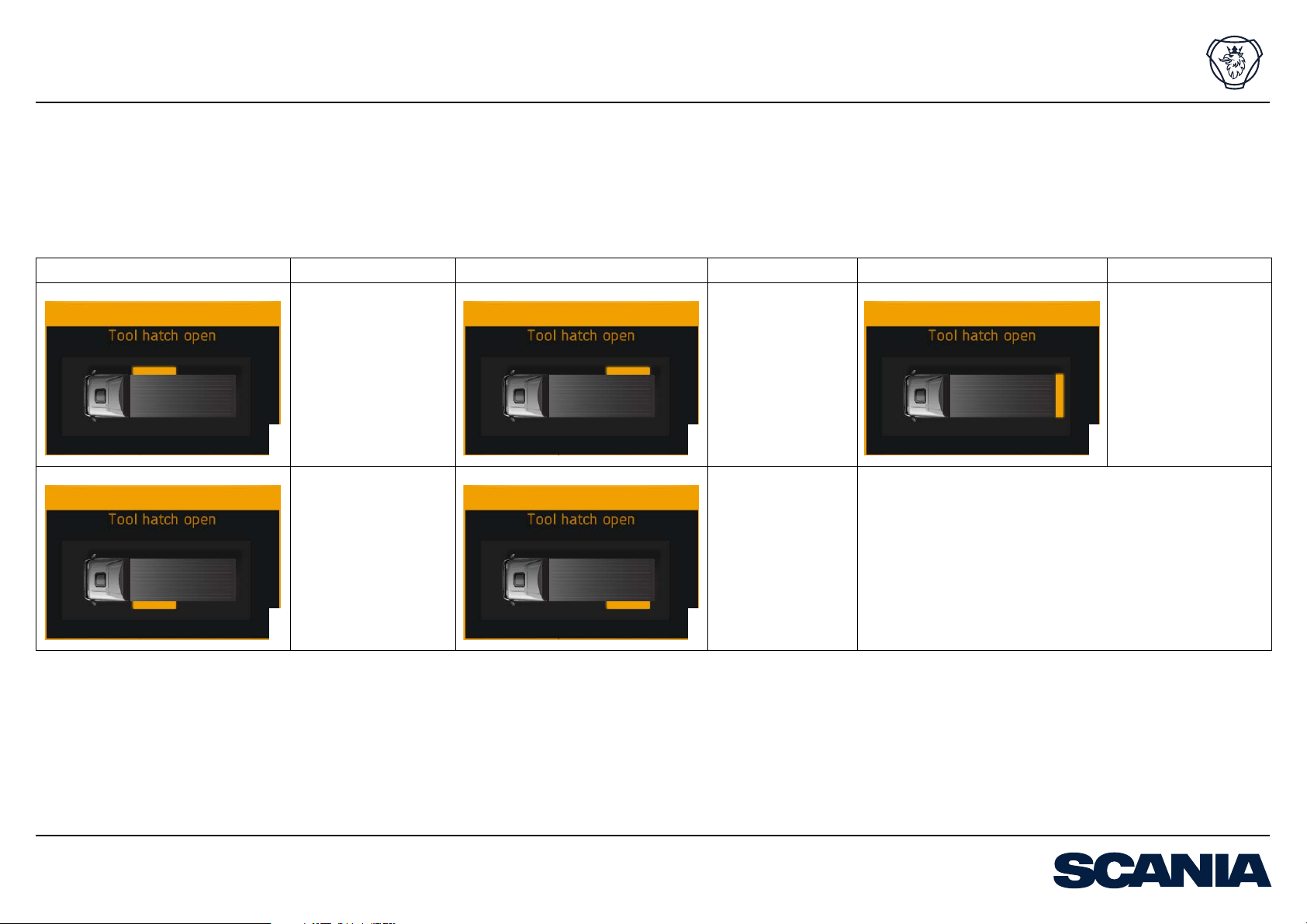
Behaviour
The warning message is presented as a display message in the instrument cluster
(ICL). The message shows where the hatch that generated the warning message is located.
Display message Description Display message Description Display message Description
Hatch open on righthand side in the front
section of the bodywork.
Hatch open on righthand side in the rear
section of the bodywork.
Hatch open at the rear
end of the bodywork.
Behaviour
Hatch open on lefthand side in the front
section of the bodywork.
370 960
Scania Truck Bodybuilder 22:10-771 Issue 1 2016-09-27
© Scania CV AB 2016, Sweden 2 (8)
Hatch open on lefthand side in the rear
section of the bodywork.
371 718
Page 3

Warning messages for open hatch
Chassis conditions
Preparations from the factory
Option Alternative Variant code
a
BCI
functionality
If required
Bodywork cable harness from cab to frame 7-pin 2411B
Bodywork cable harness in frame 2 m 3023A
a. Bodywork Communication Interface
With 5837A
7+7-pin 2411E
7+7+7-pin 2411F
8 m 3023D
12 m 3023C
Chassis conditions
Scania Truck Bodybuilder 22:10-771 Issue 1 2016-09-27
© Scania CV AB 2016, Sweden 3 (8)
Page 4

Warning messages for open hatch
Activation
Type of activation Activation method
Internal vehicle signal A function in the vehicle, fitted at the factory.
Analogue signal Via connector C259 in the bodywork console.
External CAN
a. Controller Area Network
Information on CAN messages is found in the document External CAN Communication Specification.
Activation using internal vehicle signals and analogue signals
Different functions in the vehicle are factors that affect the activation.
Internal signals in the vehicle come from a function fitted at the factory. Examples of
factors that can affect the activation by using internal signals are applied parking
brake and gearbox in drive mode.
a
network
CAN message
Activation
Use analogue signals when a factor does not generate an internal signal as above. Examples of factors that can affect the activation by using analogue signals are an activated switch in the instrument panel or a sensor in the bodywork.
Define when and how the activation is to take place by using BICT (Bodywork Interface Communication Tool) and SDP3 for bodybuilders (Scania Diagnos and Programmer 3):
1. Create a logic diagram in BICT that defines which factors shall affect the activa-
tion. Factors can be, for example, functions in the vehicle that generate internal
signals or switches that generate analogue signals.
2. Define parameters in SDP3 which state the conditions for how and when the dif-
ferent factors shall affect the activation.
Scania Truck Bodybuilder 22:10-771 Issue 1 2016-09-27
© Scania CV AB 2016, Sweden 4 (8)
Page 5

Warning messages for open hatch
The logic diagram is transferred, together with the parameters, to the vehicle’s BCI
control unit using SDP3 for bodybuilders.
More information on BICT is found in the document BCI, Bodywork Communication
Interface.
Activation by using external CAN network
When a vehicle is equipped with BCI functionality, a connection to the external CAN
network via connector C493 for bodywork is included.
• The external CAN network is activated by using SDP3 for bodybuilders.
• A CAN message defines when and how the function is to be activated.
Connection can be made either via an expansion unit or an external control unit.
Activation
Scania Truck Bodybuilder 22:10-771 Issue 1 2016-09-27
© Scania CV AB 2016, Sweden 5 (8)
Page 6

Warning messages for open hatch
Connection
Connection
The examples show a connection where each hatch has its own signal. Several hatches can also be connected in series to a common signal.
Example of an analogue connection
Pos. Designation Information
2
1 Cables Minimum permitted cable cross section is 0.75 mm
Connect the cables from C259, any position 1-10, to connector C494, any free positions. The choice of positions
in C494 affects the connection in the DIN connector on
the chassis frame.
2 Cable harness
Installed at factory.
from cab to frame
3 Cables Connect the cables from the hatch sensor to DIN connec-
tor C486, C487 or C488 depending on which positions
have been used in C494.
4 Cables Connect the sensors to a ground connection in the left-
hand frame side member.
The signal to C259 is active when the hatch is open and the circuit closed.
.
DIN
C259
C494
C259
1-10
1
C494
2
DIN
3
4
Information on ground connections is found in the document Power supply and
ground connections.
Information on the DIN connectors is found in the document Cable harnesses for
bodywork functions.
Information on the connectors is found in the following documents:
• Connector C259 – BCI-controlled functions
• Connector C494 – Bodywork functions
Scania Truck Bodybuilder 22:10-771 Issue 1 2016-09-27
© Scania CV AB 2016, Sweden 6 (8)
378 014
Page 7

Warning messages for open hatch
Example of a logic diagram in BICT
Connection
2
1
BCI master, C259-X, high ( ) or low ( )C259-X
Conditional output signal
Activate
Active
Pos. Description Options
1 Factors that will affect the activation of the function. The following options are available to select factors:
• Specific functions in the vehicle.
• Analogue signals via optional position in C259 with connection to the BCI control unit. Settings:
– Position in C259, 1-10
– High or low signal
Rewrite the text in the grey box so that it is clear from where the signal comes, for example a specific switch or sensor.
2 Only used if there are conditions that shall affect the activation
of the function.
Conditional output signal.
Values for the conditions are defined by using SDP3 for bodybuilders.
3 The function to be activated if all conditions are fulfilled. Activate warning message for a hatch.
The behaviour cannot be configured.
There are 5 functions to choose from depending on the location of the hatch.
Activate warning message
for tool compartment open
3
373 390
More information on conditional output signals is found in the document Conditional
output signals.
Scania Truck Bodybuilder 22:10-771 Issue 1 2016-09-27
© Scania CV AB 2016, Sweden 7 (8)
Page 8

Warning messages for open hatch
Connection
Example of a connection via an expansion unit or external control unit
Pos. Designation Information
1 CAN cable
a
2 Cable Connect to the external control unit/ any position 1-10
3 Cable harness Connect the sensors to a ground connection in the left-
a. A CAN cable is always pair-twisted. The pair-twisted cable consists of a cable for CAN-high and a
cable for CAN-low.
Information on ground connections is found in the document Power supply and
ground connections.
Information on connection to C493 is found in the document Connector C493 – BCIcontrolled bodywork functions.
Information on connection to the expansion unit is found in the document Installing
expansion units.
Connect the CAN cable from C493 to the external
control unit/expansion unit A.
on the expansion unit.
Minimum permitted cable cross section is 1.5 mm².
hand frame side member.
1
C493
A
1-10
A
2
3
C493
3
4
More information on CAN and external CAN network is found in the following documents:
• CAN interface for bodywork
• External CAN Communication Specification
• General information on CAN
Scania Truck Bodybuilder 22:10-771 Issue 1 2016-09-27
© Scania CV AB 2016, Sweden 8 (8)
378 014
 Loading...