

Page 1
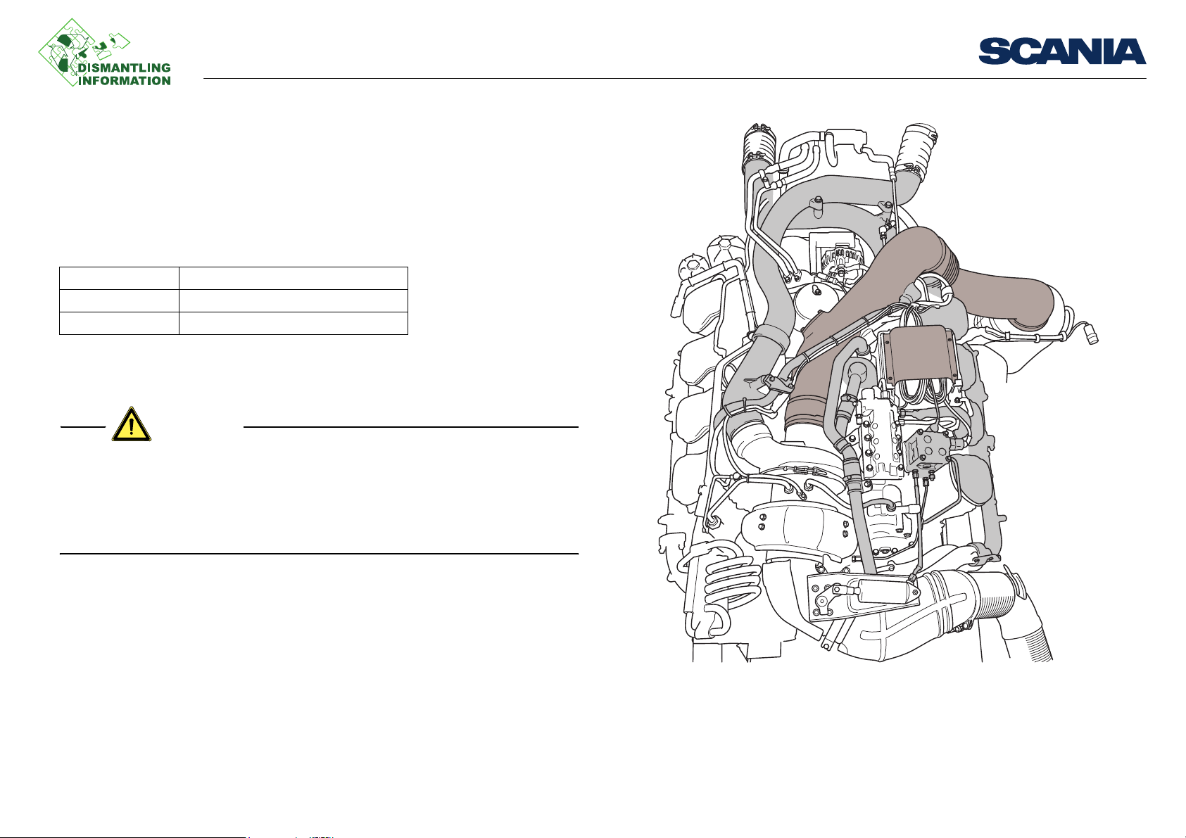
Removing the right-hand cylinder head bank
WARNING!
Remove the parts marked in grey
General
Applies to 16 litre engines with XPI and cylinder block generation 2.
Tools
Examples of suitable tools from Scania:
Part number Designation
99 614 Lifting tool
588 955 Socket
Work description
• The fuel system has a very high fuel pressure of up to 3,000 bar. The fuel system
must be depressurised using SDP3 before any work is started.
• The system should always be treated as pressurised, even when the engine is
switched off.
• Wear protective gloves and goggles.
General
Preparations
• Wash the engine
• Drain the coolant
• Evacuate the pneumatic system
03:38-00 Issue 1 en-GB 1 (8)
©
Scania CV AB 2012, Sweden
333 304
Page 2
Removing the right-hand cylinder head bank
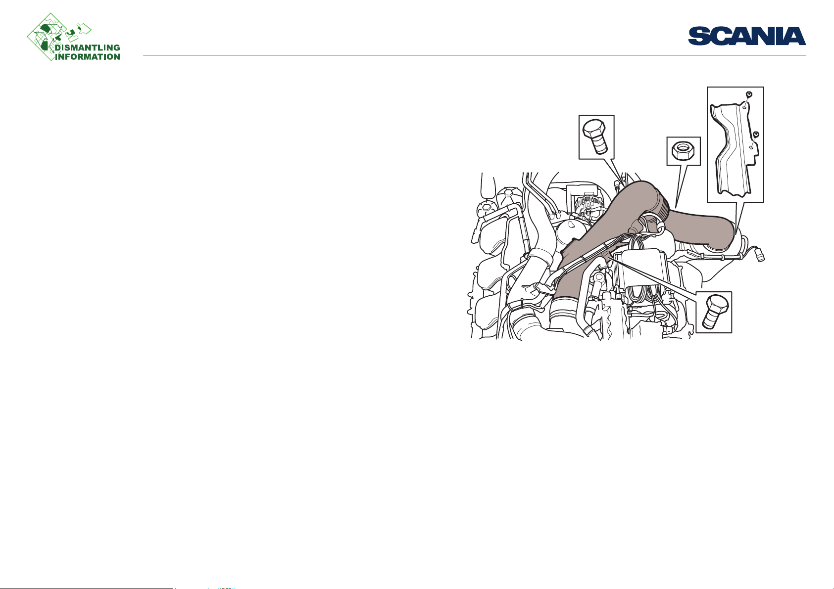
Removing various parts
Remove parts in the order below:
1. Inlet pipe between air filter and turbocharger
2. Inlet pipe to compressor
3. Control unit
4. Oil mist separator
Work description
333 299
03:38-00 Issue 1 en-GB 2 (8)
©
Scania CV AB 2012, Sweden
Page 3
Removing the right-hand cylinder head bank
212 744
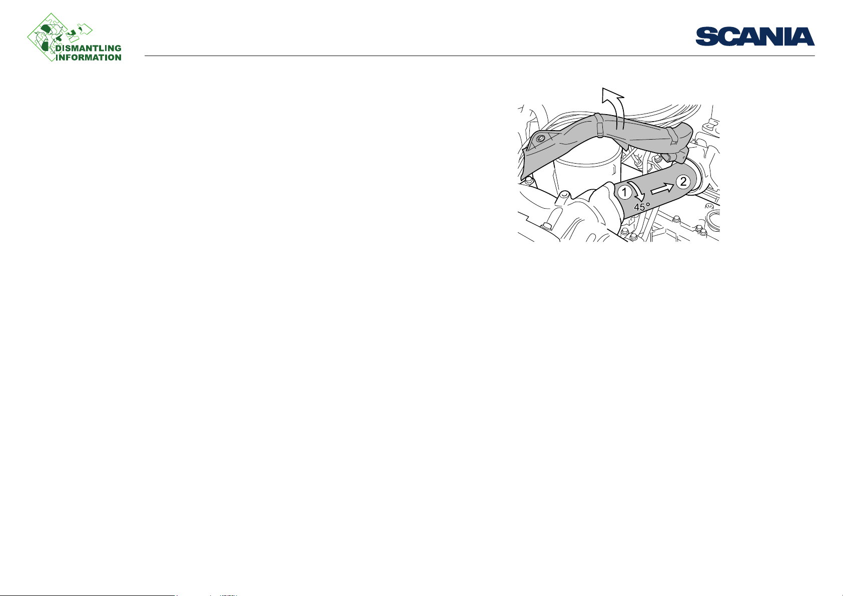
5. Connecting pipe between the intake manifolds
Work description
03:38-00 Issue 1 en-GB 3 (8)
©
Scania CV AB 2012, Sweden
Page 4

Removing the right-hand cylinder head bank
6. Bellows between charge air pipe and charge air cooler
Work description
333 301
03:38-00 Issue 1 en-GB 4 (8)
©
Scania CV AB 2012, Sweden
Page 5

Removing the right-hand cylinder head bank
7. Charge air pipe between turbocharger and charge air cooler
8. Pipe for measurement of exhaust gas pressure
9. Valve block and pressure pipe
10. Charge air pressure sensor in intake manifold
11. Temperature sensor in charge air pipe
12. Charge air pipe to intake manifolds
Work description
03:38-00 Issue 1 en-GB 5 (8)
©
Scania CV AB 2012, Sweden
Page 6

Removing the right-hand cylinder head bank
Removing the fuel system
Remove parts in the order below:
1. Test connection for fuel pressure
2. Fuel pipe between the high pressure pump and accumulator
3. Fuel pipe between the right-hand and left-hand accumulators
4. Fuel pipe between the safety valve and the high pressure pump
5. Fuel pipe between the control unit cooling coil and the high pressure pump
6. Fuel pipe between the fuel filter and the control unit cooling coil
7. Connection pipe between right-hand and left-hand fuel manifolds
Work description
330 529
03:38-00 Issue 1 en-GB 6 (8)
©
Scania CV AB 2012, Sweden
Page 7

Removing the right-hand cylinder head bank
Removing the cylinder head bank
Remove parts in the order below:
1. Fuel pipes to injectors
2. Heat shield between cylinder head 3 and exhaust manifold joint
3. Exhaust manifold on right-hand cylinder head bank
4. Upper rocker cover
5. Valve mechanism
6. Cable harness and the lower rocker cover
7. Injectors
Work description
333 302
03:38-00 Issue 1 en-GB 7 (8)
©
Scania CV AB 2012, Sweden
Page 8

Removing the right-hand cylinder head bank
333 300
8. Fit lifting tool 99 614 for removing the cylinder head bank
9. Remove bolts on the right-hand cylinder head bank and lift off the cylinder head
bank
Work description
03:38-00 Issue 1 en-GB 8 (8)
©
Scania CV AB 2012, Sweden
 Loading...