

Page 1
Removing the retarder
General
Applies to type 2 retarder.
Tools
Examples of suitable tools from Scania:
Part number Designation
87 095 Guide pins
98 257 Support drift
98 405 Bracket and fixture beam
98 765 Splined socket
99 001 Adapter
99 003 Hydraulic hole cylinder
99 004 Hydraulic pump
99 005-1 Pusher adapter
99 010 Bush, included in 99 003
99 011 Threaded bush, included in 99 003
99 012 Fully threaded spindle, see 99 006
99 040 Pusher adapter
99 497 Puller
99 497 Lifting tool
587 313 Gearbox jack
General
03:68-00 Issue 1 en-GB 1 (8)
©
Scania CV AB 2012, Sweden
Page 2
Removing the retarder
WARNING!
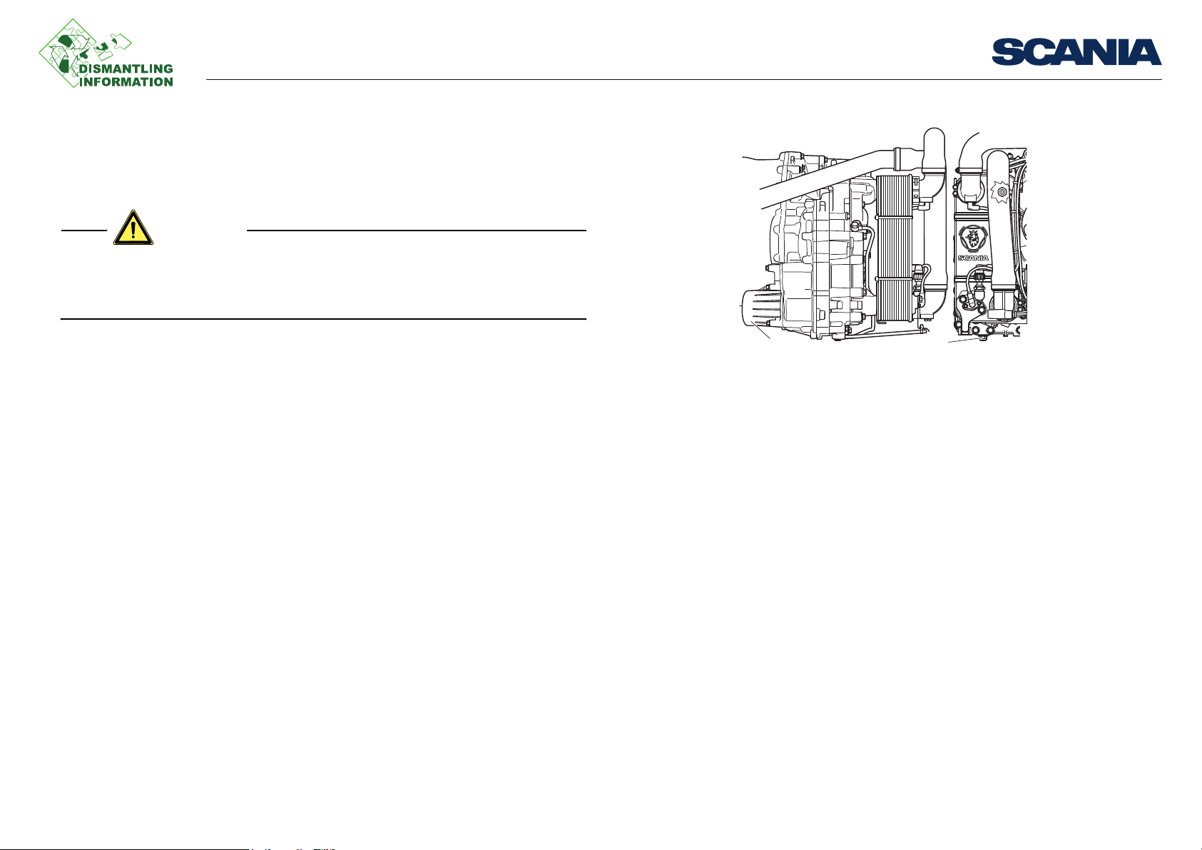
1. Plug
2. Oil filter
Work description
Draining
• Beware of hot oil after driving. Wear protective gloves and goggles.
• Make sure the compressed air tanks are empty before starting work. Oil under
pressure or blows from loose parts can cause personal injury.
Work description
R4
M1
1. Remove the plug (1) and drain the oil.
2. Drain the oil accumulator by turning the key to the drive position (pneumatic sys-
tem filled to working pressure) and move the retarder lever between the 0 position and maximum position several times, waiting for 5 seconds at each end
position.
3. Remove the oil filter (2).
2
1
311 976
03:68-00 Issue 1 en-GB 2 (8)
©
Scania CV AB 2012, Sweden
Page 3
Removing the retarder
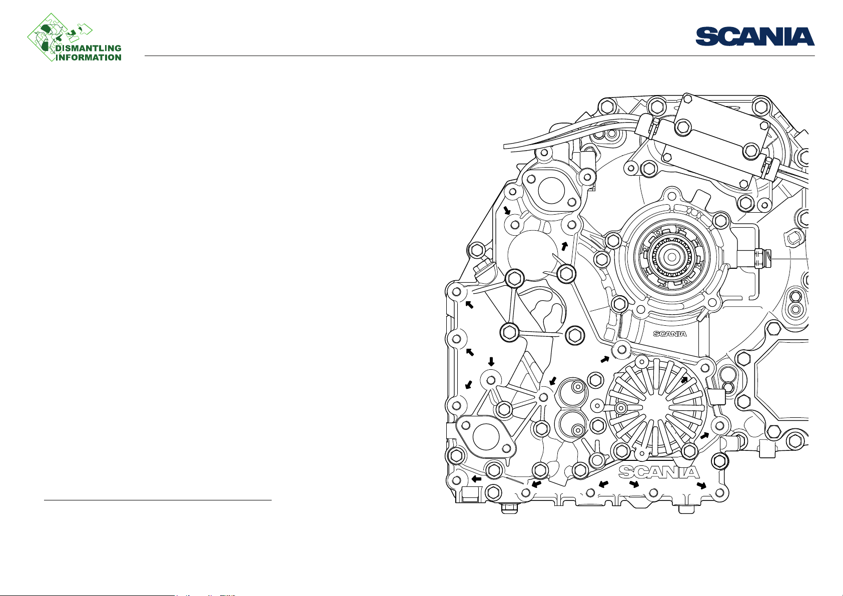
Removing
General
1. Drain the oil from the gearbox.
2. Drain the oil from the retarder.
3. Drain the coolant from the retarder.
4. Undo the hydraulic pump.
Then remove the parts as follows:
1. The upper nuts holding the coolant pipe onto the bracket.
2. Brackets for coolant pipes.
3. Connection for road speed sensor A.
4. Ventilation line.
5. 3 of the 5 screws around the output shaft.
6. All screws marked with an arrow, total 20.
1
Work description
1. Vehicles with dual-circuit steering.
03:68-00 Issue 1 en-GB 3 (8)
©
Scania CV AB 2012, Sweden
Page 4

Removing the retarder
204 096
Solenoid valve block
Solenoid valve block
1. Cut the tie straps holding the electrical cables and compressed air lines onto the
bracket on the oil cooler.
2. Remove the screws and solenoid valve block.
Work description
03:68-00 Issue 1 en-GB 4 (8)
©
Scania CV AB 2012, Sweden
Page 5

Removing the retarder
204 093
1
2
Oil cooler
1. Drain the oil and coolant. Also drain the coolant pipe between the engine and re-
tarder inlet at its lowest point.
2. Cut the tie straps securing the air lines and electrical cables to the bracket on the
oil cooler.
3. Undo and remove the clamps securing the pipe bends.
Work description
03:68-00 Issue 1 en-GB 5 (8)
©
Scania CV AB 2012, Sweden
Page 6

Removing the retarder
99498
204 094
587 313
98 405
99 498
4. Remove the lower retaining screws and bracket with sensor.
5. Fit the oil cooler in the tool as illustrated. Insert one of the attaching screws at the
arrow so that the cooler does not fall sideways.
6. Remove the upper retaining screws and remove the oil cooler.
Work description
03:68-00 Issue 1 en-GB 6 (8)
©
Scania CV AB 2012, Sweden
Page 7

Removing the retarder
98 257
99 004
99 012
99 003
99 011
99 001
99 4
99 497
A
B
End yoke
1. Remove the nut using splined socket 98 765.
2. Tighten the end yoke as indicated in alternative A or B.
Work description
03:68-00 Issue 1 en-GB 7 (8)
©
Scania CV AB 2012, Sweden
Page 8

Removing the retarder
99 498
98 405
587 313
Removed from above.
1. Hook into the retarder lifting eye.
2. Remove the remaining 2 screws around the output shaft.
3. Lower the retarder.
Removal from below
1. Fit the retarder on gearbox jack 587 313 using the tool as illustrated.
2. Remove the remaining 2 screws around the output shaft.
Work description
03:68-00 Issue 1 en-GB 8 (8)
©
Scania CV AB 2012, Sweden
 Loading...