


MODEL STHM
THIS MANUAL CONTAINS THE OPERATING INSTRUCTIONS AND SAFETY INFORMATION FOR YOUR SCAG MOWER. READING THIS MANUAL CAN PROVIDE YOU WITH ASSISTANCE IN MAINTENANCE AND ADJUSTMENT PROCEDURES TO KEEP YOUR MOWER PERFORMING TO MAXIMUM EFFICIENCY. THE SPECIFIC MODELS THAT THIS BOOK COVERS ARE CONTAINED ON THE INSIDE COVER. BEFORE OPERATING YOUR MACHINE, PLEASE READ ALL THE INFORMATION ENCLOSED.
MANUAL OPERATOR’S
© 2003 |
PART NO. 03133 |
SCAG POWER EQUIPMENT |
PRINTED 7/03 |
DIVISION OF METALCRAFT OF MAYVILLE, INC. |
PRINTED IN USA |

 WARNING:
FAILURE TO FOLLOW SAFE OPERATING PRACTICES
MAY RESULT IN SERIOUS INJURY.
*Keep all shields in place, especially the grass discharge chute.
*Before performing any maintenance or service, stop the machine and remove the spark plug wire and ignition key.
*If a mechanism becomes clogged, stop the engine before cleaning.
*Keep hands, feet and clothing away from power-driven parts.
*Read this manual completely as well as other manuals that came with your mower.
*Keep others off the tractor (only one person at a time)
REMEMBER - YOUR MOWER IS ONLY AS SAFE AS THE OPERATOR!
Hazard control and accident prevention are dependent upon the awareness, concern, prudence, and proper training of the personnel involved in the operation, transport, maintenance, and storage of the equipment.
This manual covers the operating instructions and illustrated parts list for:
STHM-23CV SM-61A SM-72A
with a serial number of 9220001 to 9229999 with a serial number of 9230001 to 9239999 with a serial number of 9240001 to 9249999
Always use the entire serial number listed on the serial number tag when referring to this product.

TABLE OF CONTENTS |
|
MODEL STHM |
|
SUBJECT |
PAGE |
Introduction .................................................................................................. |
1 |
General Safety Instructions .......................................................................... |
1 |
Signal Words ............................................................................................... |
1 |
Symbols ....................................................................................................... |
2-3 |
Before Operating ......................................................................................... |
4 |
While Operating ........................................................................................... |
4-5 |
Maintenance and Storage ........................................................................... |
5-6 |
Initial Run-In Procedures ............................................................................. |
6 |
Mower Operation ......................................................................................... |
6-7 |
Parking Brake Adjustments ......................................................................... |
8 |
Neutral Adjustment ...................................................................................... |
8-9 |
Belt Tension ................................................................................................. |
9-10 |
Belt Alignment ............................................................................................. |
10 |
Cutter Deck Adjustments ............................................................................. |
10-11 |
Cutter Blades ............................................................................................... |
11 |
Custom-Cut Baffle Adjustment..................................................................... |
11-12 |
Lubrication and Maintenance ...................................................................... |
13 |
Troubleshooting Cutting Conditions ............................................................ |
14-16 |
Technical Specifications .............................................................................. |
17-18 |
Notes .......................................................................................................... |
19 |
WE SUPPORT OPE
TECHNICIAN
CERTIFICATION

TABLE OF CONTENTS
(CONTINUED)
SUBJECT |
PAGE |
Illustrated Parts List |
|
SM 61A, 72A Cutter Deck...................................................................... |
.. 20-21 |
Engine Deck ..................................................................................... |
22-23 |
Upper Hydraulics .............................................................................. |
24-25 |
Lower Hydraulics........................................................................................ |
26-27 |
Control Linkage......................................................................................... |
. 28-29 |
Instrument Panel ............................................................................... |
30-31 |
Rider Frame Assembly ..................................................................... |
32-33 |
Brake Linkage ................................................................................... |
34-35 |
Eletrical System ................................................................................ |
36 |
Winch Lift System ............................................................................. |
37 |
Replacement Decals ........................................................................ |
|
Warranty Statement ........................................................ |
following section 8 |

INTRODUCTION |
SIGNAL WORDS |
Your mower was built to the highest standards in the industry. However, the prolonged life and maximum efficiency of your mower depends on you following the operating, maintenance and adjustment instructions in this manual.
We encourage you to contact your dealer for repairs. All Scag dealers are informed of the latest methods to service this equipment and provide prompt and efficient service in the field or at their service shop. They carry a full line of Scag service parts.
A replacement Operator's Manual is available from your Scag Servicing Dealer or by contacting Scag Power Equipment, Service Department at P.O. Box 152, Mayville, WI 53050 or contact us via the Internet at www.scag.com. Use the contact form to make your request. Please indicate the complete model and serial
number of your Scag product.
USE OF OTHER THAN ORIGINAL SCAG REPLACEMENT PARTS WILL VOID THE WARRANTY.
The “Right” and “Left”, “Front” and “Rear” of the machine are referenced from the operator’s perspective when in the normal operating position and facing the forward travel direction.
This symbol means “Attention! Become Alert! Your Safety is Involved!". The symbol is used with the following signal words to attract your attention to safety messages found on the decals and throughout this manual. The message that follows the symbol contains important information about safety. To avoid injury and possible death, carefully read the message! Be sure to fully understand the causes of possible injury or death.
Signal Word:
It is a distinctive word on safety decals and throughout this manual that alerts the viewer to the existence and relative degree of the hazard.
The signal word “DANGER” denotes that an extremely hazardous situation exists on or near the machine that could result in high probability of death or irreparable injury if proper precautions are not taken.
GENERAL SAFETY INSTRUCTIONS |
WARNING: |
|
READ THIS OPERATOR'S MANUAL and all instructions furnished with attachments.
Perform only those maintenance procedures described in this manual. If major repairs are ever needed or assistance is desired, contact an Authorized Scag Dealer. To ensure optimum performance and safety, always purchase genuine SCAG replacement parts and accessories.
Your safety and the safety of others depends significantly upon your knowledge and understanding of all correct operating practices and procedures of this machine.
The signal word “WARNING” denotes that a hazard exists on or near the machine that can result in injury or death if proper precautions are not taken.
 CAUTION:
The signal word “CAUTION” is a reminder of safety practices on or near the machine that could result in personal injury if proper precautions are not taken.
1
ISO Symbols |
CE Mark |
SYMBOL |
DESCRIPTION |
SYMBOL |
DESCRIPTION |
|
|
|
|
|
Choke |
|
Transmission |
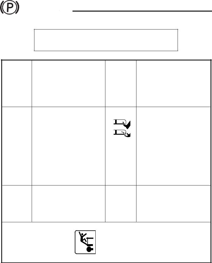
Parking Brake |
Spinning Blade |
|
48071S |
|
|
|
|
On/Start |
|
Spring Tension on Idler |
|
||
|
||
Off/Stop |
Oil |
 WARNINGFalling Hazard
FALLING HAZARD
USE ONLY SCAG APPROVED
RIDING ATTACHMENTS
SEE OPERATOR'S MANUAL 481109
2

SYMBOL |
DESCRIPTION |
SYMBOL |
DESCRIPTION |
|
|
|
|
|
Fast |
|
Slow |
Continuously Variable - Linear |
Cutting Element - Basic Symbol |
|
Pinch Point |
Cutting Element - Engage |
481039S
Hourmeter/Elapsed Operating Hours |
Cutting Element - Disengage |
Thown Object Hazard |
Read Operator's Manual |
|
|
Keep Bystanders Away |
|
3

BEFORE OPERATING |
WHILE OPERATING |
1.Know the operating controls and how to stop quickly.
2.Do not allow children to operate the machine. Do not allow adults to operate the machine without proper instruction.
3.Remove all debris or other objects that might be picked up and thrown by the cutter blades. Keep all bystanders away from the mowing area.
4.Keep all shields, safety devices, and decals in place. If a shield, safety device or decal is defective or damaged, repair or replace it before operating. Also, check all nuts, bolts and screws for proper tightness, to assure the machine is in safe operating condition.
5.Do not operate the machine while wearing sandals, tennis shoes, sneakers or shorts. Also, do not wear loose fitting clothing which could get caught in moving parts. Always wear long pants and substantial shoes. Wearing safety glasses and safety shoes is advisable and required by some local ordinances and insurance regulations.
6.Fill the fuel tank with clean, fresh gasoline, with a minimum octane rating of 87. Avoid spilling gasoline. Gasoline is highly flammable, handle it carefully.
A.Use an approved gasoline container.
B.Do not fill the tank while the engine is hot or running.
1.Start the engine when the cutter blades are disengaged, the parking brake is on and the right foot pedal is in the neutral position.
2.Do not run the engine in a confined area without adequate ventilation. Exhaust fumes are hazardous and could possibly be deadly.
3.Using the machine demands attention. To prevent loss of control:
A.Mow only in daylight or when there is good artificial light.
B.Watch for holes or other hidden hazards.
C.Do not drive close to a drop-off, ditch, creek bank, or other hazard.
D.Reduce speed when making sharp turns and when turning on hillsides.
E.Do not operate where conditions are slippery.
4.The discharge chute must always be installed and in the down position on the side discharge cutter deck except when the Scag optional grass catcher or mulching plate are properly installed. If the discharge area should plug, shut the engine off and wait for all movement to stop before removing the obstruction.
5.Disengage the blades and wait for them to stop before crossing gravel drives, walks or roads.
6.Shut the engine off and wait until the blades come to a complete stop before removing the grass catcher container.
C.Do not smoke while handling gasoline.
D.Fill the fuel tank outdoors and up to approxi- 7. Never raise the cutter deck while the blades are
mately 1" (25 mm) below the bottom of the filler neck.
E. Wipe up any spilled gasoline.
7.Before attempting to start the engine, move the blade engagement switch to the OFF position and apply the parking brake.
rotating.
8.Always park the mower and/or start the engine on a level surface. Apply the parking brake to prevent the mower from moving when you are not in the operator’s position.
4

9.If the cutting blades should strike a solid object or the equipment should start to vibrate abnormally, stop the engine, disconnect the spark plug wires, and check immediately for the cause. Vibration is generally a warning of trouble. Check the machine for damaged or defective parts. Repair any damage before starting the engine or operating the cutter deck. Be sure the blades are in good condition and the blade bolts are tight.
10.Reduce speed and exercise extreme caution on slopes and in sharp turns to prevent tipping or loss of control. Be especially cautious when changing directions on slopes.
 WARNING:
DO NOT operate on steep slopes. To check a slope, attempt to back up it (with the cutter deck down). If the machine can back up the slope without the wheels slipping, reduce speed and use extreme caution. ALWAYS FOLLOW OSHA APPROVED OPERATION.
11.Do not touch the engine or muffler while the engine is running or soon after it is stopped. These areas could be hot enough to cause a burn.
12.Before leaving the operator’s position or leaving the mower unattended, move the right foot pedal into the neutral position, apply the parking brake, and move the blade engagement switch to OFF.
Shut the engine OFF and remove the key.
13.Do not pass or stand on the grass discharge side of any mower with the engine running. Stop the cutter blades when another person approaches.
 WARNING:
Battery posts, terminals, and related accessories contain lead and lead compounds, chemicals known to the State of California to cause cancer and reproductive harm. Wash hands after handling.
MAINTENANCE AND STORAGE
1.Disconnect the spark plug wire from the spark plug to prevent accidental starting of the engine when servicing, adjusting or storing the machine.
2.If the mower must be tipped to perform maintenance or adjustment, remove the battery, drain the gasoline from the fuel tank and the oil from the crankcase.
3.To reduce potential fire hazard, keep the engine free of excessive grease, grass, leaves and accumulations of dirt.
4.Be sure the machine is in safe operating condition by keeping nuts, bolts, and screws tight. Check the blade mounting bolts and nuts frequently to be sure they are tightened.
5.If the engine must be running to perform a maintenance adjustment, keep hands, feet, clothing and other parts of the body away from the cutter deck blades and other moving parts.
6.Do not overspeed the engine by changing governor settings. To be sure of safety and accuracy, have an authorized dealer check maximum engine speed with a tachometer.
7.The engine must be shut off before checking the oil or adding oil to the crankcase.
8.Allow the engine to cool before storing the mower in any enclosure such as a garage or storage shed. Make sure the fuel tank is empty if the machine is to be stored in excess of 30 days. Do not store the mower near any open flame or where gasoline fumes may be ignited by a spark.
5

9.Always store gasoline in a safety-approved, red container.
10.Be careful when servicing the battery as it contains acid, which is corrosive and could cause burns to skin and clothing.
11.Batteries release explosive gases when being charged or discharged. Keep batteries away from any source of sparks and/or flame.
12.Make sure all hydraulic connections are tight and all hydraulic hoses and lines are in good condition before starting the machine.
13.Hydraulic fluid is under high pressure. If you need service on your hydraulic system, please see your authorized Scag dealer.
INITIAL RUN-IN PROCEDURES (FIRST DAY OF USE OR APPROXIMATELY 10 HOURS)
1.Check the belts for proper tension at 2, 4 and 8 hours. Adjust as needed. (See Belt Tension, page 9).
2.Check the neutral adjustment. (See Adjustments, page 8)
3.Check the tires for proper pressure.
Caster Wheels |
25 psi |
DriveWheels |
12 psi |
Rear Steering Wheel |
15 psi |
4.Check for loose hardware. Tighten as needed.
5.Check the safety switches for proper adjustment:
*The engine should crank and start if the machine is in neutral, the PTO engagement switch is OFF and the parking brake is ON.
7.Apply lubricant to all the grease fittings. Lubricant was applied at the factory. This is just a precautionary check to make sure that all the fittings have been lubricated.
MOWER OPERATION
1.Read and understand the safety instructions before attempting to operate this machine.
2.Before starting the engine:
*Check the oil level in the engine and the hydraulic reservoir.
*Fill the fuel tank with clean, fresh, lead-free gasoline.
*Open the fuel valve on the bottom of the fuel tank.
-NOTE-
Use gasoline with an octane rating no less than 87.
*The right hand foot pedal must be in the NEUTRAL position.
*The blade clutch switch must be in the OFF position.
*The parking brake must be ON.
3.Start the engine:
*Choke as required. If the engine is cold, pull the choke knob out. When the engine starts, slowly push the choke in. If the engine stalls, repeat the above operation. When the engine is warm, choking may not be necessary.
4.Depress the left hand operator presence pedal.
5.Engage the cutter blades by pulling the blade clutch switch into the ON position. Push the switch to the OFF position to disengage the cutter blades.
PULL UP TO ENGAGE
PUSH DOWN TO DISENGAGE
390S0138
6
-NOTE-
When the PTO is engaged or (possibly) disengaged, a squealing sound from the underside of the machine is normal. It is caused by the electric clutch plates meshing as the cutter blades come up to speed. For best equipment life, engage the clutch with the engine at 3/4 throttle, not under full load.
 WARNING:
If you are not familiar with the operation of the hydrostatic drive, practice turning and maneuvering before engaging the cutter blades.
5.Release the parking brake. Depress the right foot pedal at the toe end to drive forward (See Figure 1) or depress the pedal at the heel end to drive in reverse. (See Figure 2)
-NOTE-
The left side operator presence pedal must be depressed for operation.
sgb002
Forward Operation - Depress Toe End of Pedal
Figure 1
SGB003
Backward (Reverse) Operation - Depress Heel
End of Pedal
Figure 2
6.When driving over curbs, disengage the cutter blades and raise the cutter deck to clear the curb. Drive forward over the curb. After the curb is clear, lower the cutter deck back to normal operating position. Be sure to leave slack in the cable after lowering the cutter deck.
7.To "freewheel" or move the machine around without the engine running, rotate the dump valve lever located on the left rear of the engine deck to the freewheel position (See Figure 3). The lever must be returned to the drive position to operate the machine.
DUMP VALVE
FREE |
|
WHEEL |
DRIVE |
SGB006
Figure 3. Dump Valve Location
-NOTE-
To prevent damage to the hydraulic system, do not exceed 1MPH when moving the machine in the freewheel postion.
7

ADJUSTMENTS
PARKING BRAKE
Minor brake adjustments can be made by loosening the top nut on both brake cables (see Figure 4). Back the nuts off approximately 1/4". While pulling one cable downward, tighten the bottom nut on the cable until it touches the bottom of the brake cable mount. Tighten both the top and bottom nuts to lock the cable in place. Repeat the above steps for the second brake cable. Make sure that both cables are adjusted evenly so that the brakes do not cause the mower to pull to the left or right.
-NOTE-
This is a minor brake adjustment. If the brakes do not function properly after this adjustment, see your Scag Service Dealer before operating your mower.
Adjust
Nuts 

SGB028
Figure 4. Parking Brake Adjustment
NEUTRAL ADJUSTMENT
1.Set the engine deck up on jack stands so the wheels are free to rotate.
2.Block the caster wheels to prevent an accident should the machine fall off the jack stands.
3.Start the engine and determine if the drive wheels rotate.
If the drive wheels consistently rotate when foot pedal control is in neutral, go to step 4.
If the drive wheels inconsistently rotate, i.e. drive wheels sometimes rotate and sometimes do not when foot pedal is not depressed, then check neutral adjustment bolt for "zero free play" in neutral controlspring.
-NOTE-
If there is free play in the foot pedal have your
SCAG servicing dealer inspect the machine and repair it as needed.
4.If the drive wheels rotate in the forward travel direction, turn the adjustment bolt clockwise until the tire rotation stops. If the drive wheels rotate in the backward travel direction, turn the adjustment bolt counter-clockwise until the tire rotation stops (See Figure 5).
Neutral Control
Spring
9/16" Socket |
SGB029 |
Figure 5. Neutral Adjustment
8
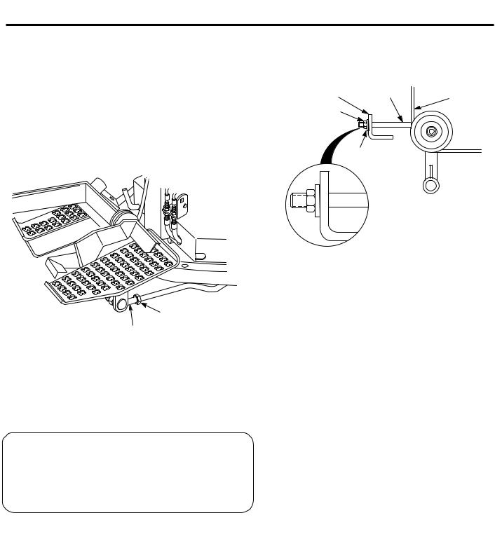
5.Check the adjustment of the right foot control pedal for full forward speed. The pedal should rest on the foot plate when the pump is stroked in the full forward position. To make an adjustment, disconnect the ball joint from the pedal arm and loosen the jam nut (See Figure 6). Place the foot control pedal forward against the foot rest and adjust the ball joint on the rod until the stud aligns with the hole in the arm. Bolt the ball joint to the arm and tighten the jamnut.
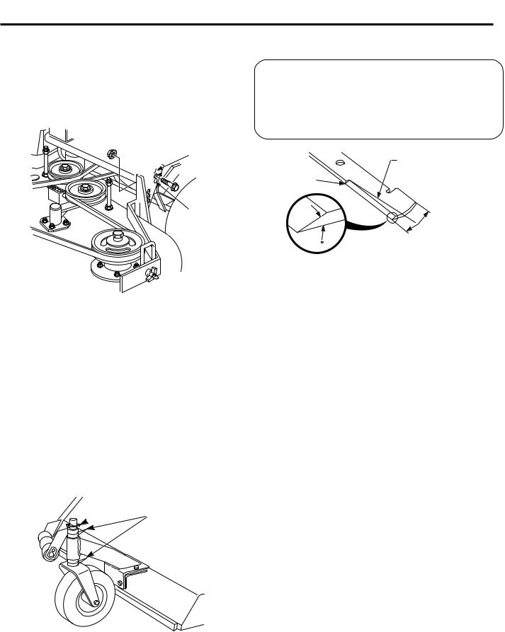
2.To adjust cutter deck drive belt: Adjust the nut so that the belt moves 1/2" with 10 pounds of pressure. (See Figure 7).
End Of L-Shaped |
"J" Bolt |
Belt |
Bracket |
|
|
|
|
|
Nut |
|
|
Washer
Jam Nut
Ball Joint |
SGB030 |
Figure 6. Foot Control Pedal Adjustment
SGB044
Figure 7. Cutter Deck Drive Belt Tension
3.To adjust blade drive belt: Using a belt tension gauge, check the belt tension so that the belt moves 1/2" with 10 pounds of pressure. (See Figure 8).
6.Start the engine. The wheels should rotate only when the foot control pedal is depressed.
BELT TENSION
 CAUTION:
Stop engine and remove the key from the ignition before making any adjustments. Wait for all moving parts to come to a complete stop before beginning work.
-NOTE-
The Hydro Drive Belt is spring-loaded and does not require adjustment.
To adjust cutter deck drive and blade belts:
1. Remove belt cover.
Use of Tension Gauge |
sgb007 |
Figure 8. Blade Drive Belt Tension Check
9

Adjust the tension by tightening or loosening the nut on the J-bolt.
Nut
 Deck
Deck
"J" Bolt
Adjusting the blade height can be done by moving any number of the five smaller spacers on the blade mounting bolts to the top or to the bottom of the spindle shaft. All blades should be positioned equally (See Figure 10).
The unit is shipped with one spacer on top of spindle and four underneath (See Figure 10).
This adjustment does not affect blade pitch.
Washer
Belt
SGB031
Figure 9. Blade Belt Tension Adjustment
4. Replace the belt covers.
BELT ALIGNMENT
Belt alignment is important for proper performance of your Scag mower. If you experience frequent belt wear or breakage, see your authorized Scag Service Dealer for belt adjustment.
Hex Nut-Torque |
Cutter Blade |
|
to 75 Lb-Ft |
||
Spacer 1/4" |
||
|
Spindle |
Cutter |
|
Deck |
||
Shaft |
||
|
Spindle |
Hex Head |
|
Assembly |
||
Bolt / Nut |
||
|
Cutter Blade
Spacers1/4"
CUTTER DECK ADJUSTMENTS
Due to the many conditions that exist, it is difficult to suggest a setting that will work for every lawn. There are, however, two adjustments that should be made on the cutter deck: pitch and height.
PITCH is the angle of the blades (comparing front to rear).
HEIGHT is the nominal distance that the blade is off the ground. This measurement is made with the blades pointed side to side and distance is measured between cutting tip and ground.
Washer
Cutter Blade
Hex Head Bolt
Figure 10. Cutter Blade Adjustment
-NOTE-
For best results, keep the cutter deck high in relation to the engine deck and the blades low in the cutter deck; ie. 4 or
5 spacers below the spindle shaft.
Additional range to the cutting height can be achieved by repositioning the cutter deck in relationship to the engine deck. This adjustment also affects the pitch of the deck.
10
There are three positions for mounting the cutter deck (See Figure 11). For cutting in the lowest position, mount the cutter deck in the top hole (A). For cutting in the highest position, mount the deck in the lowest hole
(C). Setting the cutter deck height will be determined by the type of cutting conditions.
A
 B
B
C
SGB032
Figure 11. Cutter Deck Height Adjustment
Caster spacers also can be repositioned to change the cutting heights and to change the pitch of the deck (See Figure 12).
To adjust the caster spacers, raise the deck and remove the pin and caster wheel. Reposition the caster spacers as needed, then replace the caster, top spacers and pin. Make the same adjustments on the other caster wheel.
To adjust the blade height, move any number of the five 1/4" thick spacers on the blade mounting bolts to the top of the spindle shaft or below the spindle shaft.
Pin
 Spacers
CUTTER BLADES
 CAUTION:
Blades have a sharp cutting edge. Wear protective gloves or wrap blades with protective material when removing, sharpening and installing blades.
Angle Blade Back
Do Not Cut In
X
|
X Must NOT Exceed |
|
30 |
1/3 Blade Width |
|
SGB033 |
||
|
Figure 13. Blade Sharpening
Do not sharpen beyond 1/3 of the width of the blade. (See Figure 13).
-NOTE-
Dress the blade with a file. Using a wheel grinder may burn the blade. Check the balance of the blade. If blades are out of balance, vibration and premature wear can occur. See your authorized Scag Dealer for blade balance tools.
CUSTOM-CUT BAFFLE ADJUSTMENT
The Custom-Cut Baffle is designed to deliver optimum airflow and superior cutting performance in any type of grass. The Custom-Cut Baffle can be raised or lowered to precisely tailor the deck's performance for the type of grass being cut. The baffle can be set in three (3) different positions for optimum performance.
2002SGB005
Figure 12. Repositioning Spacers
11

A.3" Position - baffle is installed using the top set of holes on the front baffle welded inside the cutter deck. (See Figure 15). The Advantage cutter deck will deliver the best quality-of-cut in very tall, wiry, tough to cut grass.
B.3-1/2" Position (factory setting) - baffle is installed using the middle set of holes on the front baffle welded inside the cutter deck. (See Figure 16). For general purpose cutting, place the Custom Cut Baffle in the 3-1/2" position. This gives the best mix of cutting performance in all types of grass.
C.4" Position - baffle is installed using the bottom set of holes on the front baffle welded inside the cutter deck . (See Figure 17). Placing the baffle in the 4" setting will enhance fall cutting (leaf pickup) and reduce cutter deck "blowout".
To adjust the Custom-Cut Baffle height:
1.Place the cutter deck in the transport position.
2.Remove the hardware securing the Custom-Cut Baffle to the cutter deck. (See Figure 14).
-NOTE-
Hardware location used in the illustrations are for reference only. Location of hardware may vary depending on cutter deck size.
MOUNTING |
MOUNTING |
|
HARDWARE |
||
HARDWARE |
||
|
2004 CCB
Figure 14. Custom-Cut Baffle
3.Move the Custom-Cut Baffle to desired position. (See Figures 15through 17 for position).
4.Reinstall the mounting hardware as shown. (See Figures 15 though 17). Torque hardware to 39ft.lbs.
TOP SET OF HOLES |
CARRIAGE BOLT |
|
FOR 3" SETTING |
||
|
|
2004 CCB - 3" Setting |
|
FLATWASHER |
ELASTIC STOP |
|
|
||
|
NUT |
|
Figure 15. 3" Custom-Cut Baffle Position |
||
MIDDLE SET OF HOLES |
CARRIAGE BOLT |
|
FOR 3-1/2" SETTING |
||
|
||
|
2004 CCB - 3-1/2" Setting |
|
FLATWASHER |
ELASTIC STOP |
|
|
||
|
NUT |
|
Figure 16. 3-1/2" Custom-Cut Baffle Position |
||
BOTTOM SET OF HOLES |
CARRIAGE BOLT |
|
FOR 4" SETTING |
||
|
||
|
2004 CCB - 4" Setting |
FLATWASHER |
ELASTIC STOP |
|
|
|
NUT |
Figure 17. 4" Custom-Cut Baffle Position
12

LUBRICATION & MAINTENANCE
|
|
|
|
|
|
|
|
|
|
|
|
* Lubrication may be required every 8 to 40 hours, depending on climate and environment. |
||||
Break-In |
|
|
||||||||||||||
|
|
|
|
|
|
+ Compatible Greases: |
Mobilux #2 found at Mobil Service Stations |
|||||||||
(1st 10 Hours) |
|
|
|
|
|
|
|
|
|
Ronex MP found at Exxon Service Stations |
||||||
|
8 Hours (Daily) |
|
|
|
|
|
|
|
|
|
Super Lube MEP #2 & Super Stay-M #2 found at Conoco Service Stations |
|||||
|
|
25 Hours |
|
|
|
|
|
|
|
|
|
Shell Alvania #2 found at Shell Service Stations |
||||
|
|
|
40 Hours (Weekly) |
|
|
|
|
|
Lidok EP #2 found at industrial shops |
|||||||
|
|
|
|
100 Hours (Biweekly) |
|
|
|
|
|
|
||||||
|
|
|
|
|
200 Hours (Monthly) |
|
|
|
|
|
||||||
|
|
|
|
|
|
500 Hours or Annually |
|
|
|
|||||||
|
|
|
|
|
|
|
|
|
|
|
|
|
|
PROCEDURE |
|
COMMENTS |
X |
|
|
|
|
|
|
|
Check all hardware |
for proper tightness |
|
||||||
X |
|
|
|
|
|
|
|
Change engine oil and filter at 5 hours |
|
|||||||
X |
|
|
|
|
|
|
|
Check hydrostatic oil level |
|
Add oil as needed - SAE 10W30 |
||||||
X |
|
|
|
|
|
|
|
Check belt tension |
|
|
||||||
|
X |
|
|
|
|
|
|
Fill fuel tank before starting |
|
|
||||||
|
X |
|
|
|
|
|
|
Check engine oil |
|
Do not over fill |
||||||
|
X |
|
|
|
|
|
|
Clean blower screen |
|
|
||||||
|
X |
|
|
|
|
|
|
Remove debris from under belt cover |
|
|||||||
|
X |
|
|
|
|
|
|
Sharpen cutter blades |
|
MORE OFTEN IF NEEDED |
||||||
|
* |
|
|
|
|
|
|
Grease spindle bearings 2 pumps of hand gun |
US Lithium MP White Grease 2125+ |
|||||||
|
X |
|
|
|
|
|
|
Clean air filter/check for damage or loose parts |
MORE OFTEN IF NEEDED |
|||||||
|
X |
|
|
|
|
|
|
Check/clean air intake and cooling areas1 |
MORE OFTEN IF NEEDED |
|||||||
|
X |
|
|
|
|
|
|
Check tire pressure |
|
Add or adjust as required |
||||||
|
|
X |
|
|
|
|
|
Service precleaner element1 |
|
|
||||||
|
|
|
X |
|
|
|
|
Check battery electrolyte level |
|
Distilled water only |
||||||
|
|
|
|
X |
|
|
|
|
|
|
||||||
|
|
|
|
|
|
|
Grease caster wheel bearings |
|
Chassis grease |
|||||||
|
|
|
|
X |
|
|
|
Grease caster wheel pivots |
|
Chassis grease |
||||||
|
|
|
|
X |
|
|
|
Grease idler arm pivots |
|
Chassis grease |
||||||
|
|
|
|
X |
|
|
|
Service air cleaner element1 |
|
See engine mfg. information |
||||||
|
|
|
|
X |
|
|
|
Change engine oil |
|
|
||||||
|
|
|
|
X |
|
|
|
Check spark plug condition and gap |
See engine mfg. information |
|||||||
|
|
|
|
X |
|
|
|
Clean cooling areas1 |
|
|
||||||
|
|
|
|
|
X |
|
|
|
|
|||||||
|
|
|
|
|
|
|
Check all hardware for proper tightness |
|
||||||||
|
|
|
|
|
X |
|
|
|
||||||||
|
|
|
|
|
|
|
Change engine oil filter |
|
See engine mfg. information |
|||||||
|
|
|
|
|
X |
|
|
Check hydro fluid reservoir level |
|
|
||||||
|
|
|
|
|
X |
|
|
Clean and adjust spark plugs |
|
See engine mfg. information |
||||||
|
|
|
|
|
X |
|
|
Grease rider frame pivot |
|
Chassis Grease |
||||||
|
|
|
|
|
|
|
|
|||||||||
|
|
|
|
|
X |
|
|
Grease control bell cranks |
|
Chassis Grease |
||||||
|
|
|
|
|
X |
|
|
Grease steering handle bearing |
|
Chassis Grease |
||||||
|
|
|
|
|
X |
|
|
Grease foot pedal bearings |
|
Chassis Grease |
||||||
|
|
|
|
|
X |
|
|
Grease rear wheel pivot (vertical) |
|
Chassis Grease |
||||||
|
|
|
|
|
|
|
|
|||||||||
|
|
|
|
|
X |
|
|
Grease rear wheel bearing |
|
US Lithium MP White Grease 2125+ |
||||||
|
|
|
|
|
|
X |
|
|
|
|
|
|
|
|
|
|
|
|
|
|
|
|
|
Drain hydraulic system and replace fluid |
Use SAE 10W30 motor oil |
||||||||
|
|
|
|
|
|
X |
|
|||||||||
|
|
|
|
|
|
|
Change hydrostatic oil filter |
|
Clean area before removing filter |
|||||||
|
|
|
|
|
|
|
||||||||||
|
|
|
|
|
|
|
|
|
||||||||
|
|
|
|
|
|
|
|
|
|
|
|
|
|
|
|
|
1. Perform these maintenance procedures more frequently under extreme dusty or dirty conditions.
13

TROUBLESHOOTING CUTTING CONDITIONS
CONDITION |
CAUSE |
CURE |
Stringers - Occasional |
Low engine RPM |
Run engine at full 3600 RPM |
Blades of Uncut |
|
|
Grass |
Ground speed too fast |
Slow speed to adjust for conditions |
|
Wet grass |
Cut grass after it has dried out |
|
Dull blades, incorrect sharpening |
Sharpen blades |
|
Deck plugged, grass accumulation |
Clean underside of deck |
Width of Deck |
Belts slipping |
Adjust belt tensions |
SGB020 |
|
|
Streaking - Strips of |
Dull, worn blades |
Sharpen blades |
Uncut Grass in Cutting |
|
|
Path |
Incorrect blade sharpening |
Sharpen blades |
|
Low engine RPM |
Run engine at full 3600 RPM |
|
Belt slipping |
Adjust belt tension |
|
Deck plugged, grass accumulation |
Clean underside of deck |
|
Ground speed too fast |
Slow speed to adjust for conditions |
|
Wet grass |
Cut grass after it has dried out |
Width of Deck |
Bent blades |
Replace blades |
|
||
SGB018 |
|
|
Streaking - Strips of |
Not enough overlapping |
Increase the overlap of each |
Uncut Grass Between |
between rows |
pass |
Cutting Paths |
|
|
Width |
Width |
of |
of |
Deck |
SGB019 Deck |
14

TROUBLESHOOTING
CONDITION |
CAUSE |
CURE |
Uneven Cut on Flat |
Lift worn off of blade |
Replace blade |
Ground - Wavy |
|
|
High-Low |
Blade upside down |
Mount with cutting edge toward |
Appearance, |
|
ground |
Scalloped Cut, or |
|
|
Rough Contour |
Deck plugged,grass accumulation |
Clean underside of deck |
|
Too much blade angle (deck pitch) |
Adjust pitch and level |
|
Deck mounted improperly |
See your authorized SCAG dealer |
|
Bent spindle area |
See your authorized SCAG dealer |
|
Dull blade |
Sharpen blade |
Width of Deck |
|
|
SGB020 |
|
|
Uneven Cut on |
Uneven ground |
May need to reduce ground speed, |
Uneven Ground - |
|
raise cutting height, and/or change |
Wavy Appearance, |
|
direction of cut |
High-Low Scalloped |
|
|
Cut, or Rough Contour |
|
|
Width of Deck |
|
|
SGB021 |
|
|
Sloping Ridge Across |
Tire pressures not equal |
Check and adjust tire pressure |
Width of Cutting Path |
|
|
|
Wheels uneven |
Check and adjust tire pressure |
|
Deck mounted incorrectly |
See your authorized SCAG dealer |
 Width of Deck
SGB023
15

TROUBLESHOOTING
CONDITION |
CAUSE |
CURE |
Scalping - Blades |
Low tire pressures |
Check and adjust pressures |
Hitting Dirt or |
|
|
Cutting Very Close to |
Ground speed too fast |
Slow speed to adjust for conditions |
the Ground |
|
|
|
Cutting too low |
May need to reduce ground speed, |
|
|
raise cutting height, change direction |
|
|
of cut, and/or change pitch and level |
|
Rough terrain |
May need to reduce ground speed, |
|
|
raise cutting height, and/or change |
|
|
direction of cut |
|
Ground speed too fast |
Slow speed to adjust for conditions |
Width of Deck |
Wet grass |
Cut grass after it has dried out |
SGB022 |
|
|
Step Cut |
Blades not mounted evenly |
Adjust pitch and level |
Ridge in Center of |
|
|
Cutting Path |
Bent blade |
Replace blade |
|
Internal spindle failure |
See your authorized SCAG dealer |
|
Mounting of spindle incorrect |
See your authorized SCAG dealer |
|
|
Width of Deck |
|
|
|
|
|
|
|
|
|
|
|
||
|
|
|
|
|
|
|
|
|
|
|
|
SGB024 |
|
|
|
|
|
|
|
|
|
|
|
Slope Cut - Sloping |
Bent spindle mounting area |
See your authorized SCAG dealer |
|||||
Ridges Across Width |
|
|
|||||
of Cutting Path |
Internal spindle failure |
See your authorized SCAG dealer |
|||||
|
|
|
|
|
|
Bent deck housing |
See your authorized SCAG dealer |
 Width of Deck
SGB025
16
 Loading...