

Sawstop Rt-tgi User Manual

INDUSTRIAL IN-LINE ROUTER TABLE
OWNER’S MANUAL
MODEL RT-TGI

Copyright SawStop, LLC
All Rights Reserved
1st printing, January 2018
Updates of this manual may be
available at www.sawstop.com
The saw shown on the front cover is the Industrial Cabinet Saw, Model ICS
with Industrial Mobile Base. Your saw may look different.
The ICS In-Line Router Table Assembly shown on the front cover includes the Stock
Guide for Router Table Fence (RT-STP). This is an optional accessory that does not
come included with your ICS In-Line Router Table Assembly. The Four-Post Router Lift
with Lock and Downdraft Dust Collection Box for Router Lift are also shown installed
on the ICS In-Line Router Table Assembly. The Four-Post Router Lift with Lock and
Downdraft Dust Collection Box for Router Lift are not included with your ICS In-Line
Router Table Assembly and your setup may look different.
SawStop, the SawStop blade logo, and the conguration of this product are either
registered trademarks or trademarks of SawStop, LLC. Software copyright by
SawStop, LLC. All rights reserved.

TO OUR CUSTOMERS
Thank you for purchasing the SawStop ICS In-Line Router Table Assembly. We are condent
you will be pleased with the quality and performance.
This manual tells you more about your ICS In-Line Router Table Assembly and how to
operate and maintain it. Please read the manual carefully. The manual also includes our
warranty and important safety information.
If you ever have any questions or comments, feel free to contact us at the address below.
SawStop, LLC
11555 SW Myslony Street | Tualatin, Oregon 97062 USA
Phone: (503) 570-3200
Fax: (503) 570-3303
Email: info@sawstop.com
www.sawstop.com

HOW TO GET HELP
Missing Parts? Have Questions?
Our technical support team is standing by
M-F, 6:30am-5pm PST
to help with whatever you need.
Give us a call at
503.582.9934
Email us at
SERVICE@SAWSTOP.COM

TABLE OF CONTENTS
Assembly Options................................................................................
Before You Begin..................................................................................
Product Specications.........................................................................
Parts Inventory.....................................................................................
Cast Iron Table Parts and Hardware.............................................................................
Support Legs Parts and Hardware...............................................................................
Power Switch Parts and Hardware................................................................................
Fence Assembly Parts and Hardware............................................................................
Assembly & Installation........................................................................
Assembling the Cast Iron Table......................................................................................
Hold-Down Strap Installation........................................................................................
Assembling and Installing the Support Legs and Power Switch...................................
In-Line Installation Left of Left Wing..............................................................................
Rail Requirements: In-Line Right of ICS Right Wing.....................................................
In-Line Installation Right: Between 36” Rails.................................................................
In-Line Installation Right: Between 52” Rails.................................................................
Assembling the Fence Assembly...................................................................................
1
4
5
6
6
7
8
9
11
11
12
16
20
22
23
25
31
Reference............................................................................................
Warranty.........................................................................................................................
Safety.............................................................................................................................
Warnings........................................................................................................................
Exploded View 1: Cast Iron Table (RT-C30) ....................................................................
Parts List 1: Cast Iron Table (RT-C30).............................................................................
Exploded View 2: Support Legs (RT-ST2).....................................................................
Parts List 2: Support Legs (RT-ST2)................................................................................
Exploded View 3: Power Switch (RT-PSW)..................................................................
Parts List 3: Power Switch (RT-PSW)...........................................................................
Exploded View 4: 32” Fence Assembly (RT-F32)...........................................................
Parts List 4: 32” Fence Assembly (RT-F32)....................................................................
Available Accessories..........................................................................
36
36
37
37
39
40
41
42
43
44
45
46
47
PAGES:
ASSEMBLY OPTIONS
1-3
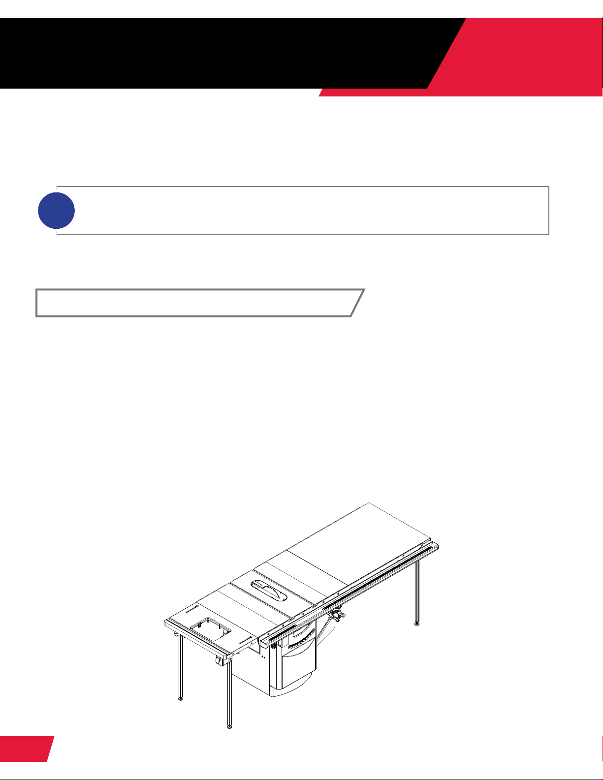
The 30” x 16” Cast Iron Router Table with 32" Fence Assembly can be mounted to your
SawStop Industrial Cabinet Saw (ICS) with T-Glide Fence System-Industrial Series II
(TGI2) rails in any of three different congurations depending on your needs.
The between-rail installation of the 30” x 16” router table is only compatible with T-Glide Fence System
i
– Industrial Series II (TGI 2) rails. If you wish to use the T-Glide Fence System – Industrial Series (CBFR)
rails, you will have to modify them signicantly.
In-Line Left of Left Wing
This conguration increases the available table space of your SawStop table saw and
provides the maximum ripping capacity to the left of the saw blade.
Required Components:
• 30” x 16” Cast Iron Router Table (RT-C30)
• Power Switch (RT-PSW)
• Support Legs (RT-ST2)
Compatible With:
• T-Glide Fence System – Industrial Series I or II (CBFR or TGI2) rails
Option 1 of 3
1
RT-TGI OWNER’S MANUAL
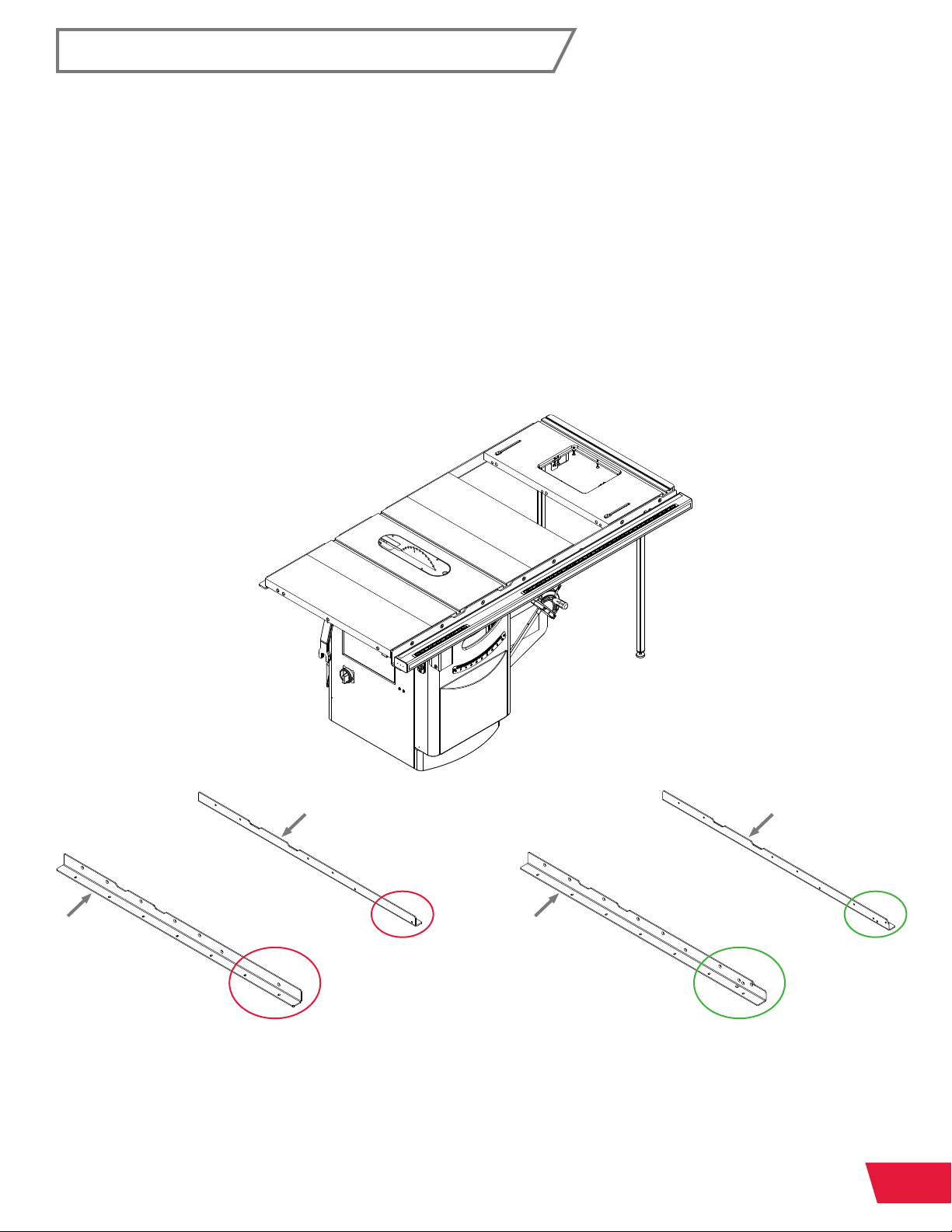
In-Line Right: Between 36” Rails
Option 2 of 3
This conguration minimizes the total footprint of your SawStop table saw and router
table. Users may choose to build an intermediate table to ll the gap between the right
extension wing and the router table (no intermediate table for this conguration is offered
by SawStop). The gap in the table measures 210mm wide.
Required Components:
• 30” x 16” Cast Iron Router Table (RT-C30)
• Power Switch (RT-PSW)
• Support Legs (RT-ST2)
Compatible With:
• T-Glide Fence System – Industrial Series II (TGI2) 36” Rails
REAR RAIL REAR RAIL
FRONT RAIL FRONT RAIL
36” CBFR105 3600 Rails
NOT COMPATIBLE
(Unless user modifies rails)
Refer to page 22 for more information on rail requirements.
36” TGI2 Rails
COMPATIBLE
RT-TGI OWNER’S MANUAL
2
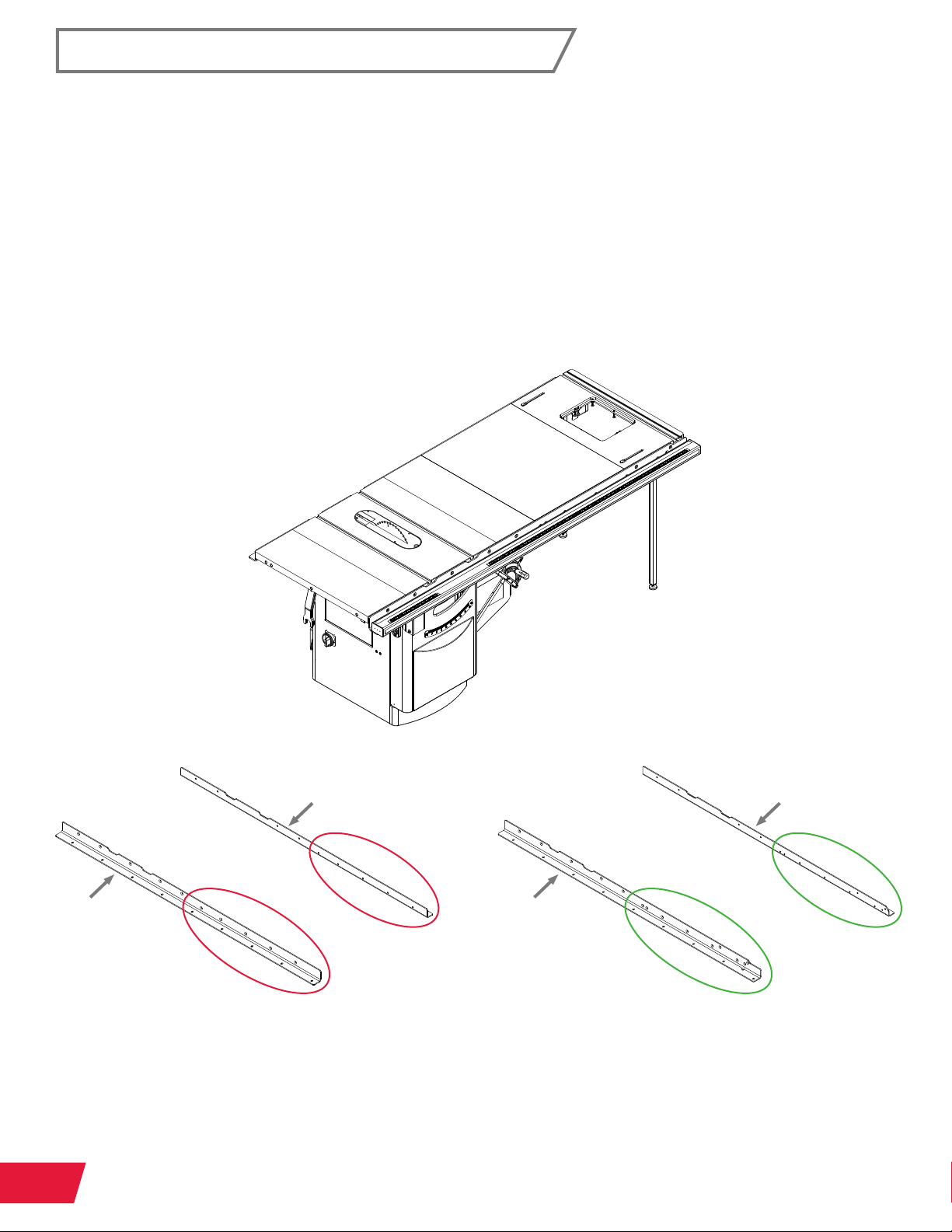
In-Line Right: Between 52” Rails
Option 3 of 3
This conguration maximizes the utility of the existing 52" rip capacity footprint.
Required Components:
• 30” x 16” Cast Iron Router Table (RT-C30)
• Power Switch (RT-PSW)
• Support Legs (RT-ST2) (Also included with 36” Extension Table)
Compatible With:
• T-Glide Fence System – Industrial Series II (TGI2) 52” Rails
• 36” Extension Table (CBFT105 3600) (NOT 52" Extension Table)
REAR RAIL REAR RAIL
FRONT RAIL FRONT RAIL
52” CBFR104 5200 Rails
NOT COMPATIBLE
(Unless user modifies rails)
Refer to page 22 for more information on rail requirements.
3
RT-TGI OWNER’S MANUAL
52” TGI2 Rails
COMPATIBLE

BEFORE YOU BEGIN
Before mounting the Cast Iron Router Table, you may need to replace or modify your rails
or other saw components. See Page 2 for compatibility notes.
Some of the steps involve removing/installing your rails and/or extension wings.
For those steps, please refer to your table saw manual and table saw fence manual.
(Download copies of your manuals at www.sawstop.com.)
DISCONNECT YOUR TABLE SAW FROM ELECTRICAL POWER BEFORE
BEGINNING ANY MODIFICATIONS.
For Unassembled Saws:
If your saw has not yet been assembled, begin by installing and aligning the right and left
extension wings as described in the installation documentation for your table saw. Then,
install the RT-compatible front and rear rails as described in your table saw fence manual,
but do not install the tube or tighten the hardware.
RT-TGI OWNER’S MANUAL
4
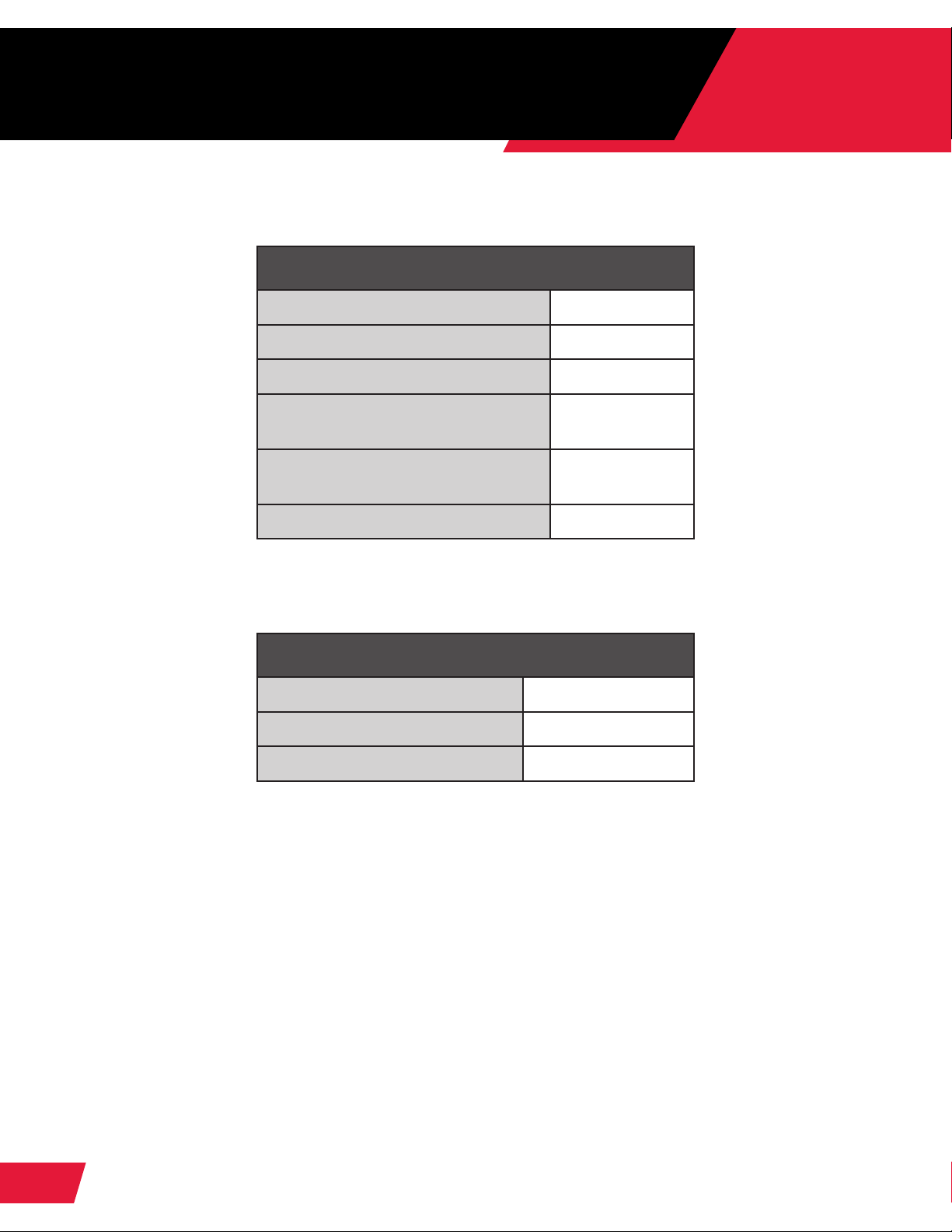
PRODUCT SPECIFICATIONS
30” x 16” Cast Iron Router Table
Cast Iron Table 30” x 16”
Maximum Fence Travel 5 ½”
Front T-slot to Arbor Center 6 ½”
Width of Front T-slot
Width of Rear T-slot
Rear T-slot to Arbor Center 5”
½” at top,
3
⁄8" at bottom
1” at top,
¾" at bottom
32” Fence Assembly for Router Tables
Length 56 ½”
Height 3 ½”
Depth 4”
5
RT-TGI OWNER’S MANUAL
PARTS INVENTORY
Please unpack the parts carefully and conrm you have received each item on
the list below.
IF YOU CANNOT FIND AN ITEM ON THIS LIST, CHECK THE MOUNTING
LOCATIONS OR EXAMINE THE PACKAGING MATERIALS VERY CAREFULLY.
CERTAIN COMPONENTS MAY HAVE BEEN PRE-INSTALLED FOR
SHIPPING PURPOSES.
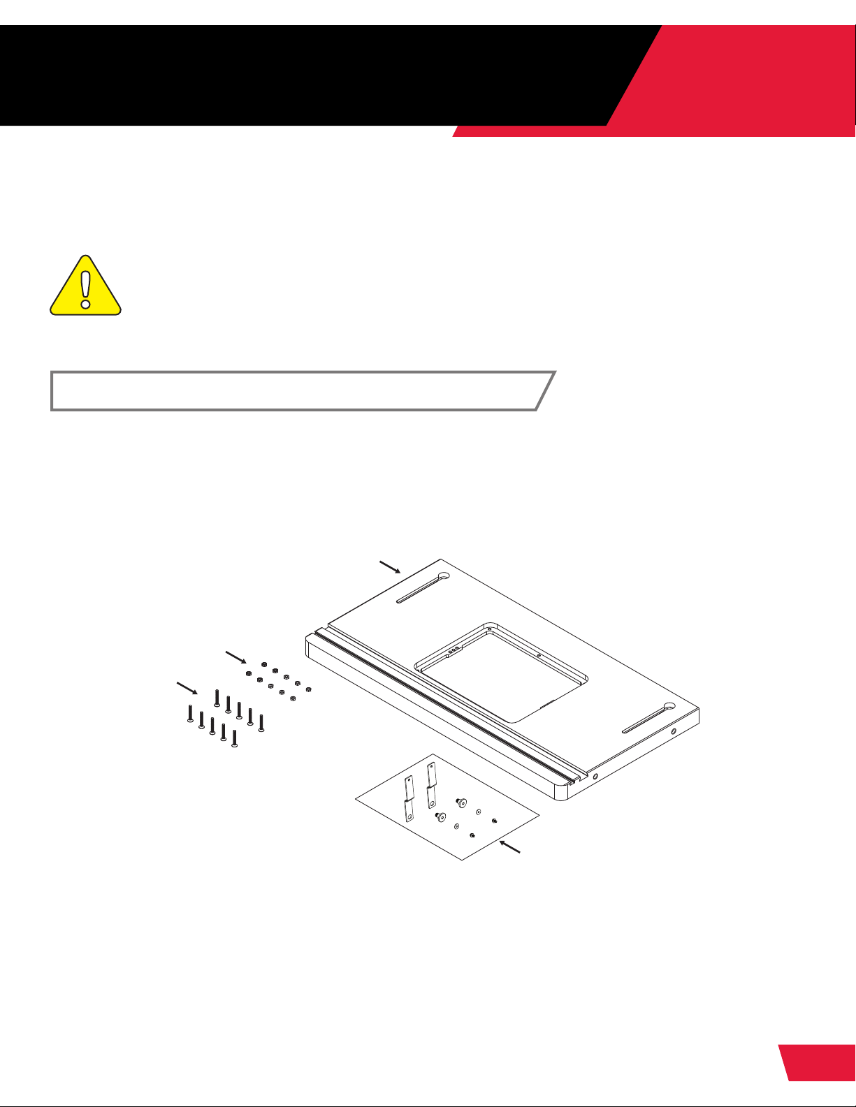
30” x 16” Cast Iron Router Table (RT-C30)
A.
30” x 16” Cast Iron Router Table (1)
B.
M6 x 1.0 Hex Nut (10)
PAGES:
6-10
C.
M6 x 1.0 x 40 Flat Head Phillips Screw (10)
D.
Mobile Base Cabinet Hold-Down Kit for Router Tables (1)
A
B
C
You will also need the following tools:
D
• Phillips Head Screwdriver
See Exploded View #1 on page 39 for more information.
RT-TGI OWNER’S MANUAL
6
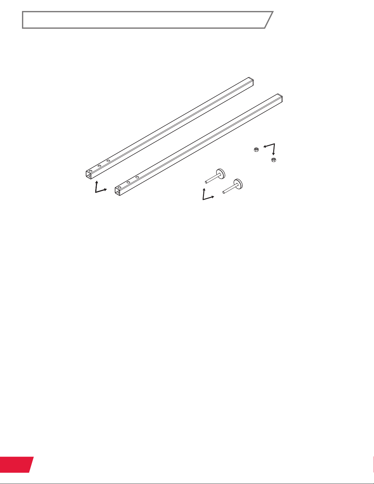
Support Legs for In-Line Router Tables (RT-ST2)
A.
Support Leg (2)
B.
M8 x 1.25 Hex Nut (2)
C.
Foot (2)
AAA
C
B
You will also need the following tools to complete the Support Legs:
• 13mm Wrench
See Exploded View #2 on page 41 for more information.
7
RT-TGI OWNER’S MANUAL
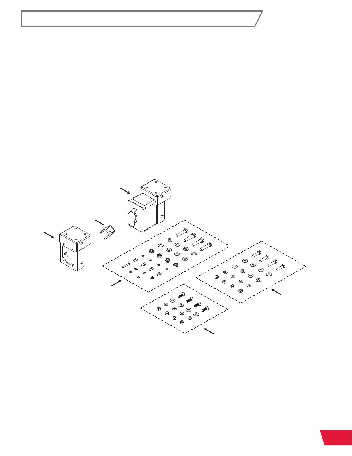
Power Switch for In-Line Router Tables (RT-PSW)
A.
In-Line Switch Box Mounting Bracket
Assembly (1)
B.
Handle Mounting Bracket (1)
C.
Leg Mounting Bracket (1)
D.
Leg Mounting Hardware Pack (1)
• M10 x 1.5 x 45 Hex Head Bolt (4)
• M10 x 19 x 2 Washer (8)
• M10 x 1.5 Lock Nut (4)
• M6 Lock Washer (4)
• M6 x 1.0 x 12 Socket Head Cap Screw (4)
• M5 x 0.8 x 30 Pan Head Phillips Screw (1)
• M5 Lock Washer (2)
• M5 x 12 x 1 Washer (2)
• M5 x 0.8 x 8 Pan Head Phillips Screw (1)
A
E.
Wing Mounting Hardware Pack (1)
• M8 x 1.25 x 45 Hex Head Bolt (4)
• M8 x 19 x 2 Washer (8)
• M8 Lock Washer (4)
• M8 x 1.25 x 12 Hex Nut (4)
Rail Mounting Hardware Pack (1)
F.
• M8 x 1.25 x 25 Flat Head Socket
Screw (4)
• M8 x 19 x 2 Washer (4)
• M8 Lock Washer (4)
• M8 x 1.25 x 12 Hex Nut (4)
B
C
D
F
You will also need the following tools to complete the Power Switch:
• Phillips Head Screwdriver
• 5mm Hex Wrench
• 16mm Wrench (x2)
• Level or Straight Edge
• 13mm Wrench (x2)
E
See Exploded View #3 on page 43 for more information.
RT-TGI OWNER’S MANUAL
8
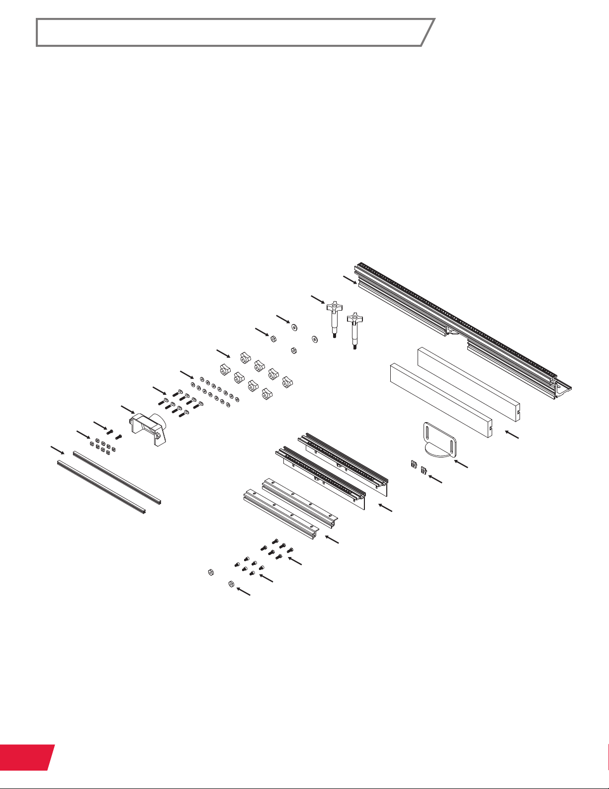
32” Fence Assembly for Router Tables (RT-F32)
A.
32” Router Table Fence (1)
B.
Fence Lock Knob (2)
C.
M8 x 23 x 2 Washer (2)
D.
23mm Lock Knob Nut (2)
E.
Fence Face Plate Lock Knob (8)
F.
M6 x 16 x 2 Washer (14)
G.
M6 x 1.0 x 35 T-Bolt (8)
H.
2 ½” Dust Port (1)
I.
¼”-20 x ¾” Pan Head Phillips Screw (2)
J.
¼”-20 Square Nut (8)
E
K.
Face Plate Space Bar (2)
L.
Router Fence Face Plate (2)
M.
Router Fence Guard (1)
N.
Router Fence Guard Spacer (2)
O.
32” Table Rail with Ruler and Lock Knob (2)
P.
Rail Mounting Bracket (2)
Q.
¼”-20 x 5⁄8” Hex Head Bolt (6)
R.
M6 x 1.0 x 12 Socket Head Cap Screw (8)
S.
19mm Lock Knob Nut (2)
A
B
C
D
F
G
H
I
J
K
N
O
P
Q
R
S
You will also need the following tools to complete the 32” Fence Assembly:
L
M
• Phillips Head Screwdriver
See Exploded View #4 on page 45 for more information.
9
RT-TGI OWNER’S MANUAL

i
Throughout the manual, the exploded views are referenced to clarify the location and
name of each part. There are multiple exploded views in this manual, so a
decimal point system is used. The number before the decimal point refers to the
exploded view number (in this case, 1 through 4). The number after the decimal point
refers to the part number (as indicated by the number in the balloon in the exploded
view). For example, a part referenced as “1.1” would be the part labeled with a “1”
balloon in the exploded view #1.
• Exploded View #1: 30” x 16” Cast Iron Router Table – See page 39
• Exploded View #2: Support Legs for In-Line Router Tables – See page 41
• Exploded View #3: Power Switch for In-Line Router Tables – See page 43
• Exploded View #4: 32” Fence Assembly for Router Tables – See page 45
Important Part Identification Note:
RT-TGI OWNER’S MANUAL
10
ASSEMBLY AND INSTALLATION
Assembling the 30” x 16” Cast Iron Router Table
Requires: 30” x 16” Cast Iron Router Table Hardware
Phillips Head Screwdriver
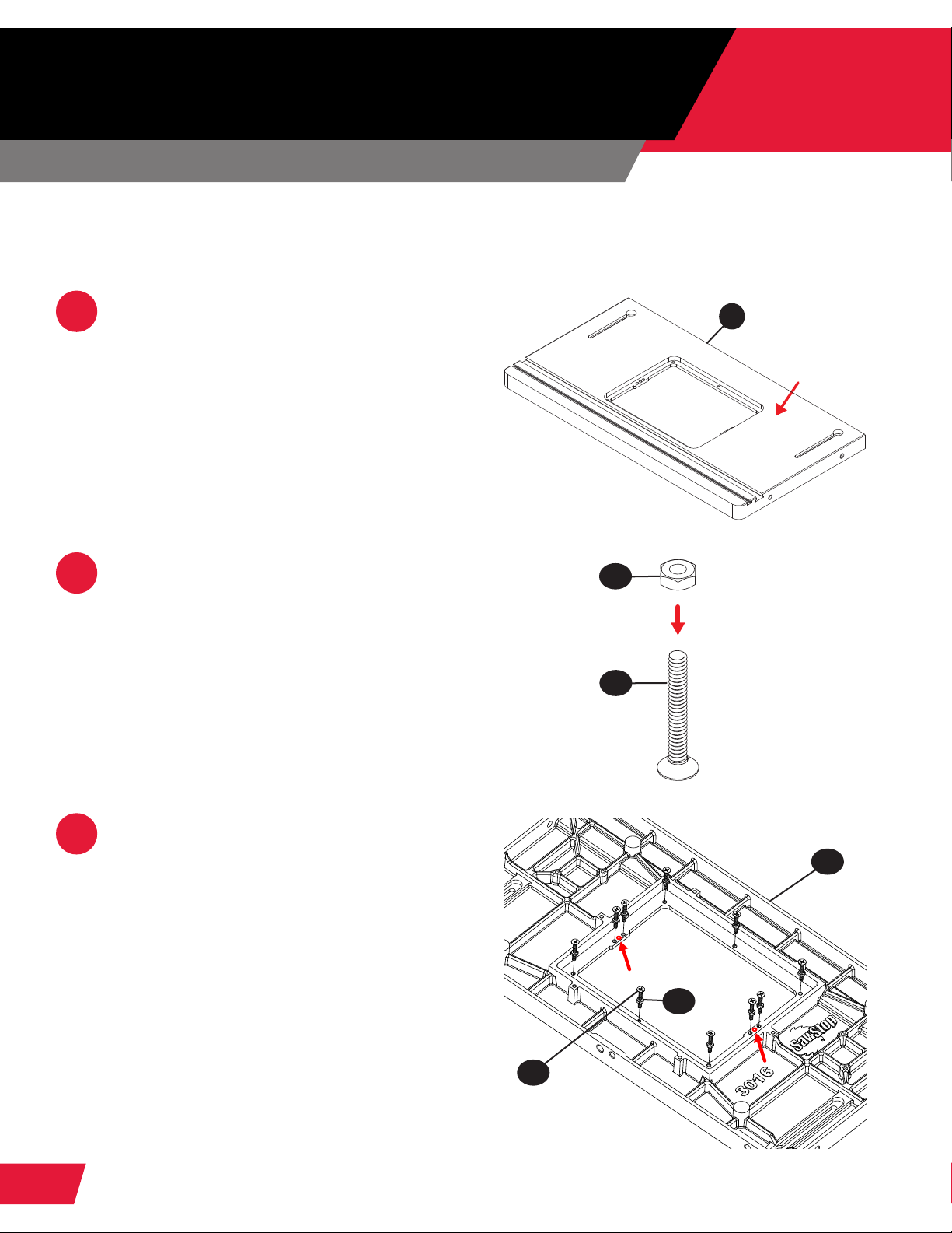
Remove the protective covering from
1
the table (1.1) and wipe off the oil with a
soft, clean cloth.
PAGES:
11-35
1.1
Thread ten M6 hex nuts (1.2) partway
2
onto ten M6 at head Phillips screws
(1.3).
Place the router table (1.1) upside down
3
on a at surface and thread the
M6 at head Phillips screws (1.3) with
prethreaded nuts into the threaded
holes around the insert opening in the
table until they extend about ¼” below
the table’s top surface. These screws
will support and level the router lift
relative to the table top. The 2 holes in
the center of the opening (shown in red)
do not receive leveling screws; they will
be used later to attach the router lift to
the router table.
1.2
x10
1.3
1.1
1.2
1.3
11
RT-TGI OWNER’S MANUAL
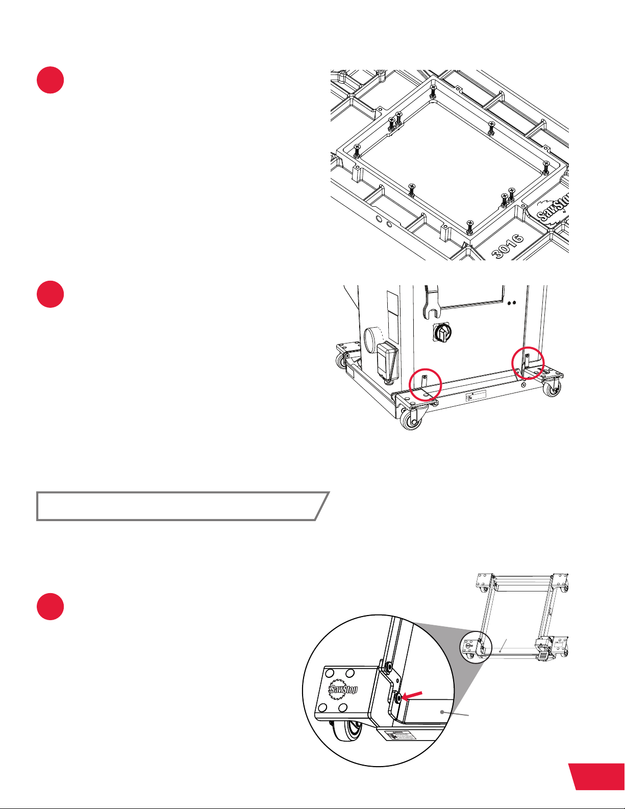
Finger tighten the hex nuts up against
Never place fingers,
toes or other body parts
under the mobile base.
!
WARNING
1. Never place fingers, toes or other
body parts under the mobile base.
2. Always use the saw and the mobile
base on a level surface.
3. Do not continue to step on the foot
pedal once the upper limit is reached.
4. Lower the saw before use. Never use
the saw when it is raised off the floor.
!
WARNING
Low
Raise
Never place fingers,
toes or other body parts
under the mobile base.
!
WARNING
4
the bottom of the table. You will adjust
the screws and fully tighten the hex nuts
later, after you install your router lift.
Your router table includes a Mobile Base
5
Hold-Down Kit (1.5). These should be
attached to your Industrial Mobile Base
now to ensure stability. If your mobile
base already has hold-down straps, the
ones included with your router table
can be discarded. Otherwise, please
complete the following steps to install
the hold-down straps. If the hold-
down straps are already installed,
or you do not have a mobile base,
proceed to page 16.
WARNING
!
Never place fingers,
toes or other body parts
under the mobile base.
Hold-Down Strap Installation
If your saw already has the Industrial Mobile Base installed without the
hold-down straps, you will need to remove the saw from the mobile base
to install the hold-down straps before proceeding.
Unscrew the M8 x 1.25 x 18 shoulder
1
socket screw at the front-left of the
mobile base in the front support strap,
as shown by the red arrow in the gure.
FRONT
SUPPORT
STRAP
WARNING
!
Never place fingers,
toes or other body parts
under the mobile base.
FRONT SUPPORT STRAP
RT-TGI OWNER’S MANUAL
WARNING
!
Never place fingers,
toes or other body parts
under the mobile base.
WARNING
!
1. Never place fingers, toes or other
body parts under the mobile base.
2. Always use the saw and the mobile
base on a level surface.
3. Do not continue to step on the foot
pedal once the upper limit is reached.
4. Lower the saw before use. Never use
Raise
the saw when it is raised off the floor.
Low
12
 Loading...