

Sawstop PCS175 User Manual
®
SawStop
10” PROFESSIONAL
CABINET SAW
OWNER’S MANUAL
Model PCS175

Copyright SawStop, LLC
All Rights Reserved.
2nd Printing, November 2012
Updates of this manual may be
available at www.sawstop.com.
The saw on the front cover is shown with the optional 36 inch
Professional Series II Fence Assembly. Your saw may look different.
SawStop, the SawStop blade logo, and the confi guration of this product are either registered
trademarks or trademarks of SawStop, LLC. Software copyright by SawStop, LLC. All rights reserved.
Protected by the following U.S. patents: 6857345, 6997090, 7024975, 7055417, 7098800, 7100483,
7197969, 7210383, 7225712, 7228772, 7284467, 7308843, 7350445, 7472634, 7481140, 7525055,
7536238, 7600455, 7610836, 7640835, 7661343, 7681479, 7707918, 7707920, 7788999, 7789002,
7827890, 7832314, 7895927, 7921754, 7958806, 7971613, 7991503, 8006595, 8011279, 8051759,
8061245, 8079292, 8087438, 8122807, 8151675, 8191450, 8196499, 8266997, 8291797, 8371196,
8402869, 8408106, 8438958, 8459157, 8469067, 8489223, 8490527, 8498732, 8505424, 8522655.
Also protected by: Australia patents 785422 and 2007201914, Canada patents 2389596 and 2660280,
China patent ZL00816099.6, India patent 212026, Japan patent 5043267, Mexico patent 250009 and
Taiwan patent 143466. Additional U.S. and foreign patents pending.

To Our Customers
Thank you for purchasing a SawStop® Professional Cabinet Saw! Your saw includes our revolutionary, awardwinning safety system that tells the difference between cutting wood and cutting a person. If you ever accidentally
contact the moving blade, the safety system will detect that contact and stop the blade in milliseconds to minimize
any injury.
This manual tells you more about your Professional Cabinet Saw and how to operate and maintain it. Please
read the manual carefully. The manual also includes our warranty and important safety information.
Again, thanks for purchasing a SawStop® Professional Cabinet Saw. W e are confi dent you will be pleased with
its performance. If you ever have any questions or comments, feel free to contact us at the address below.
SawStop, LLC
9564 S.W. Tualatin Road
Tualatin, Oregon 97062 USA
www.sawstop.com
Main Phone - (503) 570-3200
Service - (503) 582-9934
Fax - (503) 570-3303
Email - info@sawstop.com
SawStop 10” Professional Cabinet Saw 1

Table of Contents
Warranty 5
No Warranty of Safety 5
If You Have an Accident 5
Safety and Warnings 6
Warning Labels 10
The SawStop® Safety System 11
Unpacking Your Saw 14
Standing Up Your Saw 16
Assembling Your Saw 18
Installing the Elevation Handwheel 19
Installing the Tilt Handwheel 20
Installing the Dust Port 21
Installing the Motor Cover 22
Mounting the Extension Wings 23
Mounting the Switch Box 24
Mounting the Accessory Holders 25
Get to Know Your Saw 26
Preparing Your Saw for Use 28
Saw Placement 28
Table Insert Removal and Installation 28
Blade or Dado Installation 29
Brake Position Adjustment 30
Blade Guard and Riving Knife Installation 32
Dust Collection 34
Electrical Power Connection 35
Re-Wiring a PCS175 Saw for 208-240V Power 36
Changing the Plug or Power Cord on a 208-240V Saw 38
2 SawStop 10” Professional Cabinet Saw

Table of Contents
Using Your Saw 42
Adjusting the Blade Height 42
Adjusting the Blade Tilt Angle 42
Turning on Main Power and Starting the Motor 43
System Status Codes 45
Using the Blade Guard 48
Using the Riving Knife 50
Using the Miter Gauge 50
Cross-Cutting 52
Using a Fence 53
Rip Cutting 54
Using the Saw in Bypass Mode 57
Using a Mobile Base 58
Using an Out-Feed Table 59
Changing the Brake Cartridge 60
Installing a Brake Cartridge 63
What to do if the SawStop® Safety System Activates 64
Making Adjustments to Your Saw 65
Aligning the Table 65
Aligning the Blade to the Tilt Axis 69
Aligning the Blade Elevation Assembly 72
Adjusting the Elevation Limit Stops 74
Adjusting the Tilt Limit Stops and Tilt Angle Indicator 75
Adjusting the Table Insert 77
Aligning the Riving Knife and Spreader to the Blade 79
Adjusting the Quick-Release Clamp 82
Adjusting the Miter Gauge 83
Adjusting the Motor Belt Tension 84
Adjusting the Tilt Gearing 84
Adjusting the Elevation Gearing 85
SawStop 10” Professional Cabinet Saw 3

Table of Contents
Maintenance 86
SawStop Safety System 86
Brake Cartridge 86
Elevation and Tilt Mechanisms 86
Cabinet 86
Table and Extension Wings 86
Belts 86
Lubrication Points 87
Troubleshooting 88
Professional Cabinet Saw Specifi cations 91
Professional Cabinet Saw Dimensions 92
Push Stick Construction 94
Auxiliary Fence Construction 95
Push Block Construction 96
Featherboard Construction 97
Drawings and Parts Lists 98
Cabinet and Table Exploded View 98
Cabinet and Table Parts List 99
Internal Assembly Exploded View 102
Internal Assembly Parts List 103
Arbor Assembly Exploded View 106
Arbor Assembly Parts List 107
Blade Guard and Miter Gauge Exploded View 110
Blade Guard and Miter Gauge Parts List 111
Literature, Hardware and Tools Parts List 112
Accessories 113
Index 114
4 SawStop 10” Professional Cabinet Saw

Warranty
SawStop warrants to the original retail purchaser of a new Professional Cabinet Saw accompanying this
manual and purchased from an authorized SawStop distributor that the saw and any accessories purchased with
the saw will be free from defects in material and workmanship for TWO YEARS from the date of purchase.
SawStop warrants to the original retail purchaser of a refurbished, demonstration or fl oor model Professional
Cabinet Saw from an authorized SawStop distributor that the saw will be free from defects in material and
workmanship for ONE YEAR from the date of purchase.
This warranty does not apply to defects arising from misuse, abuse, negligence, accidents, normal wear-andtear, unauthorized repair or alteration, or lack of maintenance. This warranty is void if the saw or any portion of the
saw is modifi ed without the prior written permission of SawStop, LLC, or if the saw is located or has been used
outside of the country of residence of the authorized SawStop distributor from whom the saw was purchased.
Please contact SawStop to take advantage of this warranty. If SawStop determines the saw or an accessory
is defective in material or workmanship, and not due to misuse, abuse, negligence, accidents, normal wear-andtear, unauthorized repair or alteration, or lack of maintenance, then SawStop will, at its expense and upon proof
of purchase, send replacement parts to the original retail purchaser necessary to cure the defect. Alternatively,
SawStop will repair the saw or accessory provided the saw or accessory is returned to SawStop, shipping prepaid,
with proof of purchase and within the warranty period.
SawStop disclaims any and all other express or implied warranties, including merchantability and fi tness for a
particular purpose. SawStop shall not be liable for death, injuries to persons or property , or incidental, consequential,
contingent or special damages arising from the use of the saw.
This warranty gives you specifi c legal rights. You may have other rights which vary from state to state.
No Warranty of Safety
It is important to understand that the braking technology in SawStop table saws does not prevent contact
with the blade-it minimizes the effect of the contact. If you do contact the blade, the braking technology will stop
the blade, and in most cases there will be no injury or only a small nick. However, you may incur a serious injury
on a SawStop saw depending on factors such as the speed and direction your hand is moving when it contacts the
blade and the type of blade you are using. Also, if you decide to use the saw in Bypass Mode, the safety system will
be disabled and will not activate in the event you contact the spinning blade.
If You Have an Accident
We at SawStop hope you never have an accident with your saw, and strongly encourage you to always follow
safe practices and to use all the safety equipment provided with this saw. However, if you ever accidentally contact
the spinning blade, the safety system will detect that contact and stop the blade within milliseconds to minimize any
injury. If this happens, please contact us with information regarding the accident because it is very important to our
on-going research and development. The more we know about what happens during an accident, the better we are
able to ensure that the safety system will react as quickly as possible in all accident situations. In addition, the brake
cartridges store electronic data measured during an accident. If you return the activated cartridge to SawStop,
we can retrieve that data to learn how the electronics and software performed. If we confi rm that your cartridge
activated due to skin contact, we will send you a free replacement cartridge. Thanks for your help.
SawStop 10” Professional Cabinet Saw 5

Safety
A table saw is a dangerous tool and there are hazards inherent with using this saw. Some of these hazards
are discussed below. Use common sense when operating the saw and use the saw only as instructed. You are
responsible for your own safety!
!
WARNINGS
1. Read and understand the instruction manual and all safety warnings before operating this saw. Failure to follow
instructions or heed warnings may result in electric shock, fi re, serious personal injury or property damage.
Save these instructions and refer to them whenever necessary.
2. WARNING: This product contains one or more chemicals known to the State of California to cause cancer and
birth defects or other reproductive harm. In addition, some types of dust created by sawing, power sanding,
grinding, drilling, and other construction activities also contain chemicals known to cause cancer, birth defects
or other reproductive harm. Some examples of these chemicals are lead from lead-based paints, crystalline
silica from bricks, cement, and other masonry products, and arsenic and chromium from chemically treated
lumber. In addition, wood dust has been listed as a known human carcinogen by the U.S. government. The
risk from exposure to these chemicals and to dust varies depending on how often you do this type of work. To
reduce your exposure, work in a well ventilated area and work with approved safety equipment including dust
masks or respirators designed to fi lter out such dust and chemicals.
3. THIS SAW MUST BE CONNECTED TO A GROUNDED WIRING SYSTEM or to a system having an equipment-
grounding conductor. In the event of a malfunction or breakdown, grounding provides a path of least resistance for
electric current to reduce the risk of electric shock. This saw is equipped with an electric cord having an equipment-
grounding conductor and a grounding plug. The plug must be plugged into a matching outlet that is properly installed
and grounded in accordance with all local codes and ordinances. Do not modify the plug provided - if it will not fi t the
outlet; have the proper outlet installed by a qualifi ed electrician. Improper connection of the equipment-grounding
conductor can result in a risk of electric shock and/or malfunction. The conductor with insulation having an outer
surface that is green with or without yellow stripes is the equipment-grounding conductor. If repair or replacement of
the electric cord or plug is necessary , do not connect the equipment-grounding conductor to a live terminal.
Check with a qualifi ed electrician or service personnel if the grounding instructions are not completely understood or
if in doubt as to whether the saw is properly grounded. Use only 3-wire extension cords that have 3-prong grounding
plugs and 3-pole receptacles that accept the saw’s plug. Repair or replace a damaged or worn cord immediately.
4. USE PROPER EXTENSION CORD. Make sure your
extension cord is in good condition. When using an
extension cord, be sure to use one heavy enough to carry
the current your saw will draw. An undersized cord will
cause a drop in line voltage resulting in loss of power and
overheating. For a cord length of up to 25 feet on 110-
120V power, use a cord of 12 gauge. For a cord length of
25 to 50 feet on 1 10-120V power, use a cord of 10 gauge.
A cord length over 50 feet is not recommended for 110-
120V power. If in doubt, use the next heavier gauge. The
smaller the gauge number the heavier the cord.
Minimum Extension Cord Gauge
for 110-120V
Length Gauge
0 - 25 Feet 12 AWG
25 - 50 Feet 10 AWG
over 50 Feet Not Recommended
6 SawStop 10” Professional Cabinet Saw
!
WARNINGS
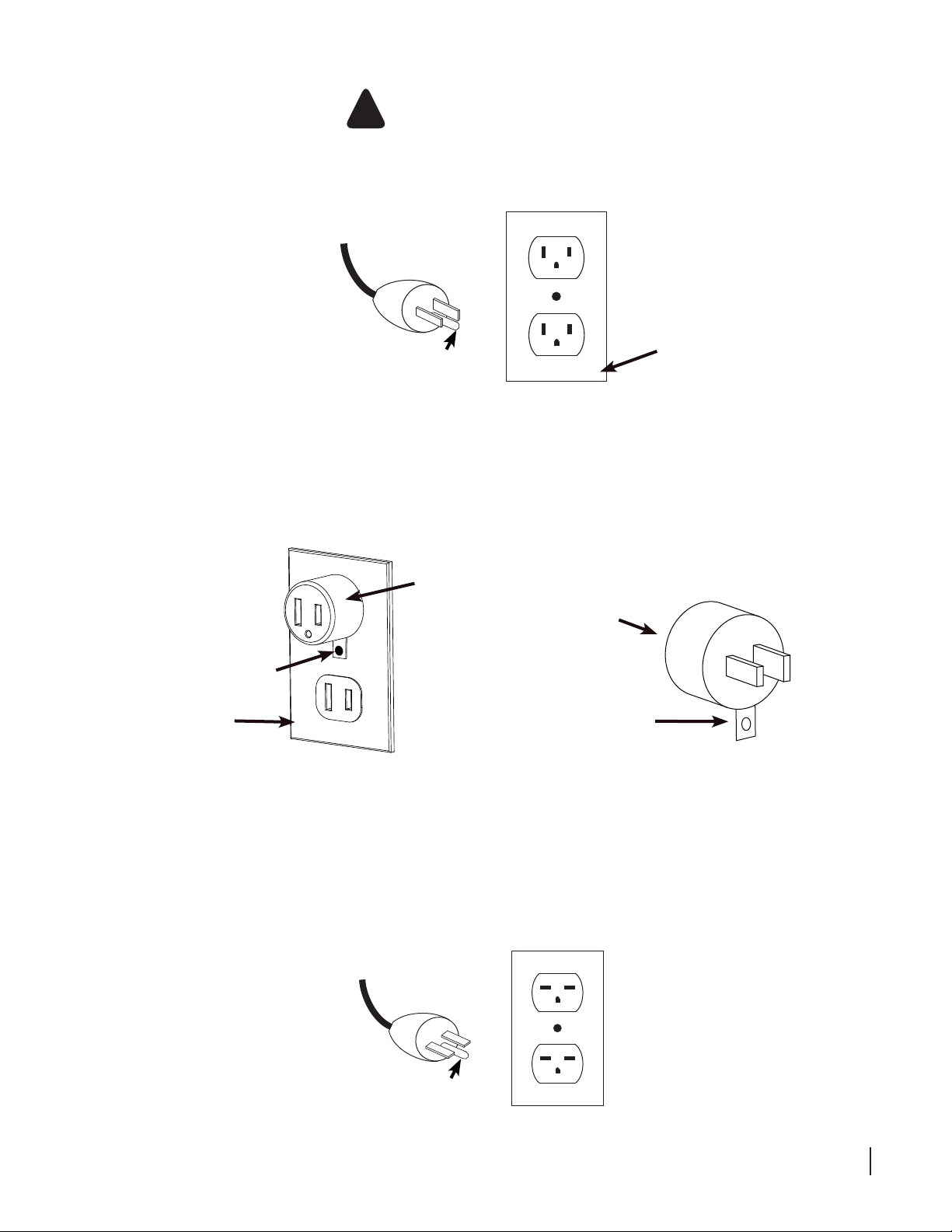
5. Professional Cabinet Saw Model PCS175 in its standard confi guration is intended for use on a 110-120V
supply circuit that has an outlet that looks like the one illustrated in Sketch A below.
Sketch A
cover of grounded
grounding pin
A temporary adapter , which looks like the adapter illustrated in Sketch B and C, may be used to connect this plug
to a 2 pole receptacle as shown in Sketch B if a properly grounded outlet is not available. The temporary adapter
should be used only until a properly grounded outlet can be installed by a qualifi ed electrician. This adapter
is not permitted in Canada. The green-colored rigid ear, lug, and the like, extending from the adapter must be
connected to a permanent ground such as a properly grounded outlet box.
outlet box
Sketch B
adapter
adapter
metal screw
cover of grounded
outlet box
6. Professional Cabinet Saw Model PCS175 re-wired for 208-230V power is intended for use on a circuit that has
an outlet that looks like the one illustrated in Sketch D. The saw has a grounding plug that looks like the plug
illustrated in Sketch D. Make sure the saw is connected to an outlet having the same confi guration as the plug.
No adapter is available or should be used with this saw. If the saw must be reconnected for use on a different
type of electric circuit, the reconnection should be made by qualifi ed service personnel; and after reconnection,
the saw should comply with all local codes and ordinances.
Sketch C
grounding
means
Sketch D
grounding pin
SawStop 10” Professional Cabinet Saw 7

!
WARNINGS
7. KEEP CHILDREN AWAY from the saw. All visitors should be kept at a safe distance from the work area. Make
the workshop kid-proof with padlocks, master switches, or by removing starter keys.
8. Do not use the saw in dangerous environments. For example, do not use the saw in damp or wet locations or
expose it to rain, and keep the work area well lighted.
9. Check to make sure the saw is in proper working order before using the saw. For example, check the alignment
of moving parts, look to see whether moving parts are binding or rubbing, check to see whether parts are broken,
make sure accessories are properly mounted in the saw, and check any other conditions that may affect the
operation of the saw. A guard or other part that is damaged should be properly repaired or replaced.
10. Keep guards in place and in working order. Never operate the saw with the motor cover or access panels open.
11. Wear eye protection. Always wear safety glasses when using the saw. Everyday eyeglasses are not safety
glasses. Also use a face or dust mask if the cutting operation is dusty.
12. Wear proper apparel when using the saw. Do not wear loose clothing, gloves, neckties, rings, bracelets, or
other jewelry which may get caught in moving parts. Non-slip footwear is recommended. Wear a protective hair
covering to contain long hair.
13. You must install a rip fence before using this saw. Attempting to use the saw for rip cutting without the rip fence
could result in serious personal injury.
14. REDUCE THE RISK OF UNINTENTIONAL STARTING. Make sure the power switch is in the OFF position
before plugging in the saw. Also, remove adjusting keys and wrenches from the saw before turning it on.
15. Keep hands out of the line of the saw blade. Never reach around or over the saw. Do not overreach or stretch
to get something when using the saw. Keep proper footing and balance at all times.
16. Never stand on the saw. Serious injury could occur if the saw is tipped or if the cutting tool is unintentionally contacted.
17. Feed work into the blade against the direction of rotation of the blade only. Feeding the work in the direction of
rotation may cause the work to be thrown by the blade and could result in serious personal injury.
18. Do not perform any operation freehand. Freehand means not using a fence (for rip cuts) or a miter gauge (for
cross-cuts) to guide the work piece as it is being cut. Always maintain fi rm control over the material being cut.
19. Use a blade guard and spreader for every operation for which it can be used, including all through sawing.
Use a push stick when required.
20. Secure your work. Use clamps or a vise to hold work when practical. It’s safer than using your hand and it frees
both hands to operate tool.
21. Pay particular attention to instructions on reducing the risk of kickback. Kickback occurs when a work piece
contacts the downstream edge of the blade as it is being cut and is propelled back towards the user at high
velocity.
22. DON’T FORCE THE TOOL. It will do the job better and safer at the rate for which it was designed. For example,
do not try to cut wood faster than the motor can handle.
8 SawStop 10” Professional Cabinet Saw

!
WARNINGS
23. USE THE RIGHT TOOL. Do not try to force the saw to do something it was not designed to do. Don’t force a
tool or attachment to do a job for which it was not designed. Use the right blade for the job.
24. Never leave the saw running unattended. Wait until the blade comes to a complete stop and then turn the main
power switch to OFF and unplug the power cord when you are fi nished using the saw.
25. Turn the main power switch to OFF and unplug the power cord before servicing the saw and when changing
components or accessories such as blades, brake cartridges, and the like.
26. MAINTAIN TOOLS WITH CARE. Maintain the saw as specifi ed in this manual. Keep tools sharp and clean for
best and safest performance. Follow instructions for lubrication and changing accessories.
27. Use only recommended accessories with the saw. Consult this manual for recommended accessories. The use
of improper accessories may cause risk of injury. When servicing, use only identical replacement parts.
28. Keep the top of the saw clean and free from clutter. Cluttered areas invite accidents.
SawStop 10” Professional Cabinet Saw 9

Warning Labels
Warning labels are mounted on the right and back sides of the saw , on the
table insert, on the switch box, and on the motor cover. Some of the warnings
on those labels may be additional to the warnings listed above. Be sure to
read the warning labels before using the saw. Copies of the English text of the
warning labels are reproduced below:
!
WARNING
To avoid loss of SawStop
protection during coast down,
do not turn off Main Power until
blade has stopped spinning.
WARNING
!
Do not operate with door open.
The blade can retract and cause
a severe injury if you touch it inside
the cabinet. Also, moving parts can
cut, pinch or crush.
WARNING
!
Moving gears and parts
can pinch, cut or crush.
Do not operate with
door open.
Thank you for
purchasing this
SawStop
This saw is equipped with the
SawStop
reduce the potential for a serious injury
in the event of accidental contact with the
®
safety system, designed to
®
table saw.
saw blade.
!
WARNING
For your own safety,
read the instruction manual
before operating this saw.
1. Wear eye protection.
2. Use the blade guard and spreader
for every operation for which it can
be used, including all through
sawing.
3. Keep hands out of the line of the
saw blade.
4. Use a push-stick when required.
5. Know how to reduce the risk
of kickback.
6. Do not perform any operation
freehand.
7. Never reach around or over the
saw blade.
8. Never try to test fire the brake
system.
9. Never adjust the position of the
brake cartridge while the blade is
spinning.
10. Do not try to disable the brake
system.
11. Unplug the saw before changing
the blade, changing the brake
cartridge or servicing.
12. Do not connect the motor directly
to a power supply.
13. Use the bypass switch only when
necessary.
14. Do not expose to rain or use in
damp locations.
15. Do not put your hands inside or
underneath the cabinet while the
blade is spinning.
16. Do not unplug or disconnect the
saw from electrical power before
the blade has stopped spinning.
17. If connected to a circuit protected
by fuses, use time delay fuse
marked D.
WARNING
!
This saw operates differently than
ordinary table saws. Each operator
must read and understand the
Owner’s Manual before
operating this saw.
10 SawStop 10” Professional Cabinet Saw
Moving belts and parts
can pinch, cut or crush.
Do not operate with
door open.
The SawStop Safety System
This Professional Cabinet Saw is equipped with the SawStop® safety system. This revolutionary technology
was developed to reduce the potential for a serious injury in the event of accidental contact with the saw blade.
SawStop® saws are the only saws smart enough to know the difference between you and the wood you are
cutting.
The SawStop® safety system includes two components, an electronic detection unit and a fast-acting brake.
The electronic detection unit detects when a person contacts the blade. A small electrical signal is induced onto the
blade by electrodes placed around the arbor. Although
this low voltage, high frequency signal is too small to
feel, it can be measured by the detection system. When
human skin comes into contact with the blade (or arbor),
a portion of the signal is absorbed by the body due to
the inherent electrical capacitance of the human body.
As a result, the signal on the blade gets smaller and the
detection unit recognizes this as contact.
Wood and other non-conductive materials such as
plastic, foam, cardboard, Corian®, melamine, etc., do
not cause a drop in the signal because those materials
do not absorb the signal on the blade. Conductive
materials such as aluminum and other metals, carbon
fi ber materials, mirrored acrylic, carbon-fi lled materials,
etc., will typically cause the brake to activate. If you need
to cut these conductive materials, the safety system can
be placed in “Bypass Mode” to temporarily disable the
brake. (The Bypass Mode is discussed on page 57.)
®
Brake Cartridge
The fast-acting brake includes a small fuse that holds a strong spring in compression. If the electronic detection
unit detects contact while the blade is spinning (including during coast down), the fuse is burned by a surge of
electric current. The spring then pushes an aluminum pawl into the teeth of the spinning blade. The teeth cut into
the pawl, stopping the blade. The total time between the detection of contact and stopping the blade is just a few
milliseconds. If the brake is activated while the blade is at or near full speed, the blade will also quickly retract below
the table. The system will not activate the brake when the blade is stopped–even if you spin the blade by hand. This
allows you to touch or change the blade when the motor is off just as with ordinary table saws. However , for safety,
always turn the main power switch to OFF and unplug the power cord when changing the blade.
The SawStop® safety system is active whenever the main power is on. The safety system continuously performs
many different self-checks to ensure that the components of the system are operating properly. If any problems are
detected, the safety system will disable the motor and display a system status code to identify the problem (see
page 45 for a description of the system status codes and the corrective action). If the problem is detected while
the motor is spinning, the motor will be shut off. The safety system will not allow the motor to start, even in Bypass
Mode, as long as a problem is detected.
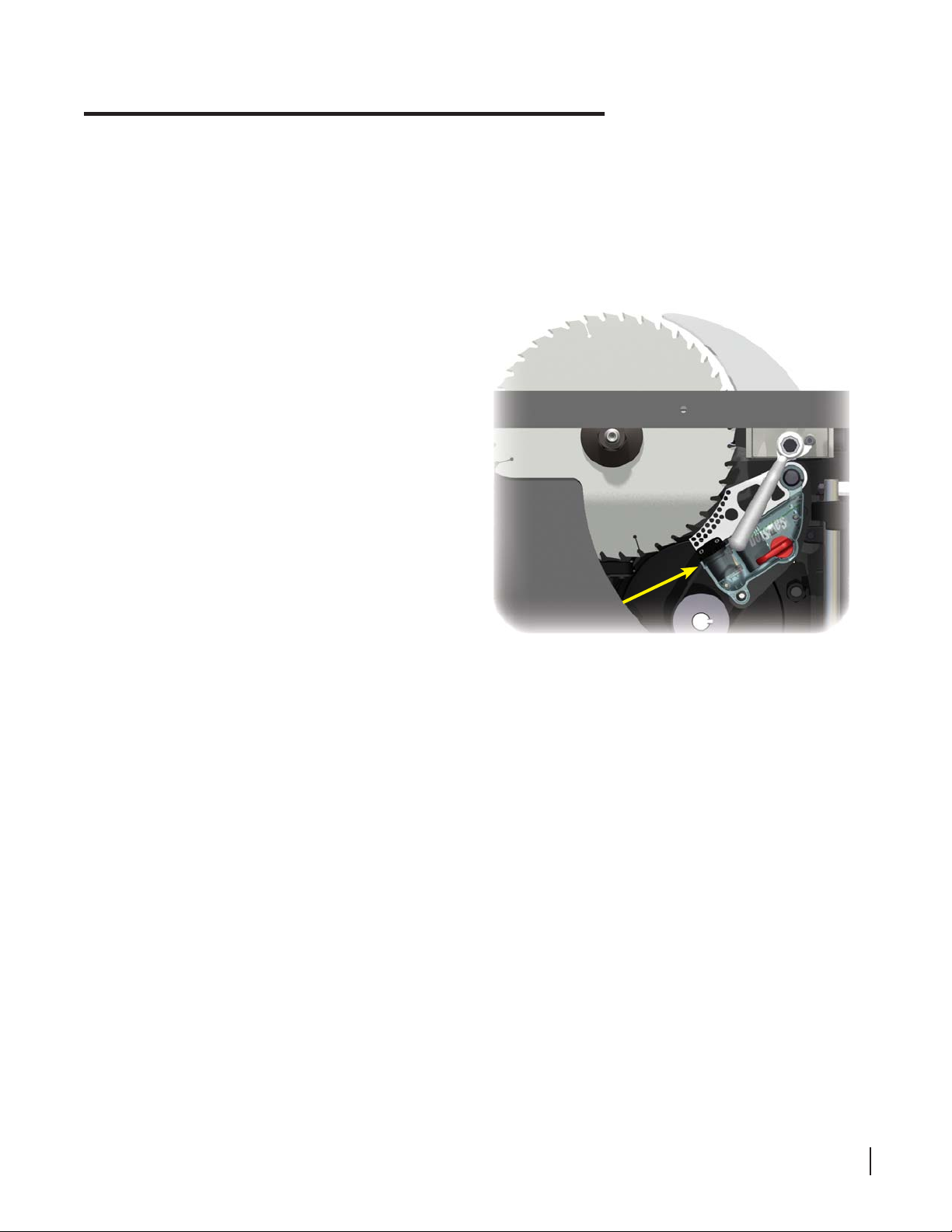
The electronic detection unit and fast-acting brake are contained in the “brake cartridge,” which is positioned
under the table and just behind the blade, as shown above. The brake cartridge must be correctly installed before
the motor can be started (see page 61 for instructions on removing and installing the brake cartridge). In the event
that the brake is activated, a new brake cartridge must be installed before the saw can be used again.
SawStop 10” Professional Cabinet Saw 11

The SawStop Safety System
®
The SawStop® safety system does not interfere with your use of the saw. You can still make all the cuts that
you can with ordinary saws including 0° to 45° bevels, non-through cuts, and dado cuts (with the optional dado
brake cartridge and the optional dado table insert).
Your SawStop® saw operates differently than ordinary table saws, and there are a few important points to keep
in mind as you use the saw.
1. Do not rely on the SawStop® safety system to protect against unsafe operation. Although the system is
designed to react and stop the blade very quickly in the event of accidental contact, it cannot react until contact
is detected. This means that you may receive at least a minor injury even with the SawStop® safety system.
Therefore, always use safe operating practices, and use the blade guard, push stick and other safety devices
whenever possible. The SawStop® safety system, like the airbag in a car, should be considered as a last
measure to minimize injury when all other safety practices and devices have failed to prevent an accident.
2. In the event of contact, the blade will be stopped in about 3–5 milliseconds (coarse toothed blades stop more
quickly than fi ne-toothed blades such as plywood blades). Therefore, the seriousness of the injury incurred will
depend on the speed at which a person’s hand or other body part is moving toward the blade. For example, if
a person’s hand is moving toward the blade at 1
ft.
(1
⁄
0.005 sec. = 0.005 ft. or 1⁄16 inch). At faster speeds, the cut will be proportionally deeper. Therefore,
sec.*
it is possible to be seriously injured even with the SawStop® safety system.
3. Do not operate the saw in Bypass Mode unless you are cutting electrically conductive material. When Bypass
Mode is engaged, the SawStop® safety system will not activate the brake if contact is detected and a serious
injury could result if you contact the blade.
ft.
⁄
, then the depth of the cut will be approximately 1⁄16 inch
sec.
4. The motor cannot be started without a blade installed. Since the safety system disables the motor if the blade
is spaced too far from the brake, a missing blade will be detected as a blade-to-brake spacing error and the
motor will be disabled.
5. Blades
Y ou can use any standard 10 inch saw blade or 8 inch dado set with your SawStop® saw, although the following
precautions should be observed:
i. Never attempt to use a blade other than a single 10 inch blade with the standard SawStop® brake cartridge.
Never attempt to use a dado set or blade other than an 8 inch dado set with the SawStop® dado cartridge.
The use of smaller diameter blades with a brake cartridge designed for larger blades could result in a
serious injury because the brake cannot be positioned correctly to stop the smaller blades.
ii. Never stack dado blades thicker than 13⁄16 inch. The 8 inch dado brake cartridge is not designed to stop
dado stacks thicker than 13⁄16 inch.
iii. Do not use molding heads. The use of molding heads could result in a serious injury because neither the
standard brake cartridge nor the dado brake cartridge is designed to stop a molding head.
iv. Never use a blade with damaged or missing teeth as this can result in a more serious injury or a false activation
of the brake. Blades with variable spacing between teeth are compatible with the SawStop® safety system,
however you must ensure the brake is positioned correctly by rotating the blade at least one full revolution to be
certain that none of the teeth touch the brake (see page 30 for more information on setting the brake position).
v. Never install the blade backwards. The brake might not stop a blade that is installed backwards.
vi. Do not use saw blades or dado sets that have a lacquer or other coating on the teeth. These coatings
are non-conductive and therefore can reduce the speed at which the system detects contact. In other words,
a coated tooth must cut slightly deeper into the skin for contact to be detected, resulting in a somewhat
more serious injury . Used blades that originally had a coating are OK to use since the coating is worn away
within a few uses. However, SawStop recommends that you examine each tooth on such blades to confi rm
that no coating remains.
12 SawStop 10” Professional Cabinet Saw

The SawStop Safety System
vii. Blades with depth-limiting shoulders may take longer to stop in the event of an accident than standard
blades, and you could receive a more serious injury . Therefore, SawStop recommends using blades without
depth-limiting shoulders.
viii. The SawStop safety system is designed for use with standard 10 inch blades with kerfs from 3⁄32 inch to
3
⁄16 inch. Blades with kerfs much thinner than 3⁄32 inch should not be used because those blades might not
be strong enough to withstand the force applied by the brake when it activates. As a result, those blades
might deform and stop more slowly in the event of an accident, resulting in a more serious injury. Blades
with kerfs much thicker than 3⁄16 inch are heavier than standard 1⁄8 inch kerf blades, and should not be used
because they may stop more slowly than standard blades in the event of an accident, resulting in a more
serious injury. Similarly, stacks of two or more 10 inch blades should never be used on your SawStop saw
as the combined weight of the blades may be too heavy to stop quickly. If you need to use a blade with a
kerf thicker than 3⁄16 inch, use an 8 inch dado set with the optional Sawstop 8 inch dado brake cartridge.
ix. Do not use non-conductive blades, including abrasive blades, blades with plastic hubs, or blades that
have non-conductive teeth. The safety system cannot induce the electrical signal onto a non-conductive
blade, and blades with non-conductive teeth may prevent the system from detecting contact. Only standard
steel blades with either steel or carbide teeth should be used.
6. Do not use table inserts, guards, fences or other devices which have metal parts that may come into contact
with the blade. Any metal part that contacts the blade may cause the brake to activate. All SawStop® accessories
are specifi cally designed to prevent metal contact with the blade.
®
7. Wet, pressure-treated wood may cause the brake to activate. The chemicals used to pressure treat wood often
contain large amounts of copper, which is conductive. When pressure-treated wood is wet, the combination of
copper and water substantially increases the conductivity of the wood. Therefore, allow wet pressure-treated
wood to fully dry before cutting. Typically, the wood will be suffi ciently dry if left unstacked in a dry location for
24 hours. If you must cut wet pressure-treated wood, you can make several cuts in the wettest piece(s) using
the Bypass Mode to test whether the wood is too wet. See page 57 for instructions on using Bypass Mode and
page 47 for information on testing the conductivity of a material. If the test indicates the wood is too wet to cut with
the safety system active, you must either allow the wood to dry or make the remaining cuts in Bypass Mode.
8. Do not replace the arbor belt with a non-SawStop® belt. The SawStop® arbor belt is custom designed to dissipate
static electricity that may build up on the spinning blade which could cause a false activation of the brake.
9. Never touch the arbor, arbor pulley, arbor nut or arbor washer when the blade is spinning because you may
receive a serious injury . These parts are all electrically coupled to the blade and the brake will activate if contact
with these parts is detected.
10. Never reach under the blade while it is spinning. In the event the brake is activated, the retraction of the blade
may cause a serious injury if you contact the bottom of the blade.
11. Do not remove the dust shroud because a large portion of the blade will be exposed. If you contact the blade
under the table, the blade may retract toward you and cause a severe injury.
12. Do not unplug or disconnect the saw from electrical power before the blade has stopped spinning. If the power
is interrupted while the blade is moving, the safety system will not be active and therefore the brake will not
activate in the event of accidental contact. You may receive a serious injury if you contact the spinning blade
while the electrical power has been interrupted.
13. Never attempt to disable the SawStop® safety system or modify the electrical wiring of the saw in any way . Any
change or modifi cation or disablement of the safety system or other wiring could result in a serious injury and
will void all warranties.
14. Never attempt to repair, adjust, modify or otherwise service a brake cartridge. There are no user-servicable
parts inside the brake cartridge. The brake cartridge is permanently sealed against dust and other contaminants.
Destruction, removal, or alteration of this seal voids all warranties.
SawStop 10” Professional Cabinet Saw 13
Unpacking Y our Saw
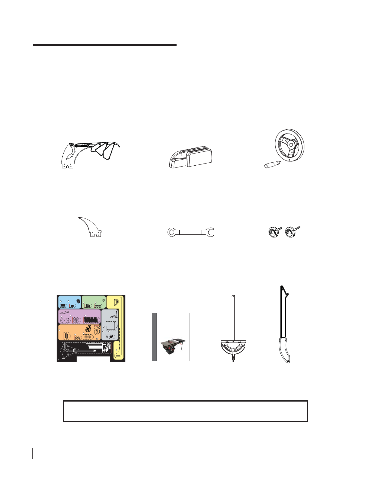
Remove all packing materials and accessories before removing the saw from the shipping pallet. While
unpacking your saw verify that all the components shown on this page and the following page are included. Use
care when unpacking your saw to prevent damage to any of the saw components or accessories. If the saw or
the accessories have been damaged during shipping, report the damage to your shipper before proceeding with
unpacking. Read and understand this manual fully before assembling and operating your saw.
blade guard assembly
riving knife
(installed in saw)
Installing the Handwheels
Hardware for Steps 2-3
1
Keys,
5 x 5 x 25 (2)
Washers,
6
M8 (8)
Mounting the Switch Box
9
Button Head Socket Screws,
M6 x 20 (2)
F
Mounting the Dust Port
2
Button Head Screws,
Set Screws,
M5 x 3 x 15 (3)
M6 x 8 (2)
3
Mounting the Extension Wings
Hardware for Step 6
8
7
Lock Washers, M8 (8)
Hardware for Step 7
Washers, M6 (2)
11
Lock Washers,
M6 (2)
10
Blade Spacing
Adjustment Gauge (1)
Hex Key, M8 (1)
Tools
Hardware for Step 4
Lock Washers,
M5 (3)
4
Hex Bolts, M8 x 16 (8)
Switch Box
Keys (2)
12
Hex Keys: M3 (1), M4 (1), M5 (1), M6 (1)
Mounting
the
Motor
Cover
Hardware for Step 5
Mounting the
Wrench & Tool
Holders
Hardware for Step 8
Blade
Wrench
Holder
13
15
14
Lock
Washers,
M6 (2)
Button Head
Screws,
M6 x 12 (2)
Motor
Cover
Rod
5
accessory tool holder
blade wrenches
(two)
CABINET SAW
OWNER’S MANUAL
Model PCS175
®
SawStop
10”PROFESSIONAL
owner’s manualtable saw hardware pack
miter gauge
handwheel package
(two)
lock knobs
(two)
push stick
WARNING! The saw weighs approximately 247 pounds without the extension wings and
317 pounds with the extension wings. Be careful in handling the saw to avoid injury.
14 SawStop 10” Professional Cabinet Saw
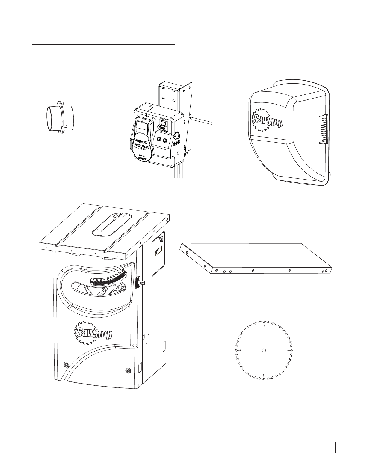
Unpacking Y our Saw
dust port
(attached to the end
of the flexible hose
inside of the saw)
switch box assembly
(connected to the saw
by electrical cables)
motor cover
ith door open.
w
WARNING
ct and cause
!
ou touch it inside
t operate
Do no
The blade can retra
a severe injury if y
the cabinet. Also, moving parts can
cut, pinch or crush.
table saw
(with pre-installed zero-clearance table insert,
brake cartridge, and brake cartridge key)
extension wings
(two)
10” blade
SawStop 10” Professional Cabinet Saw 15
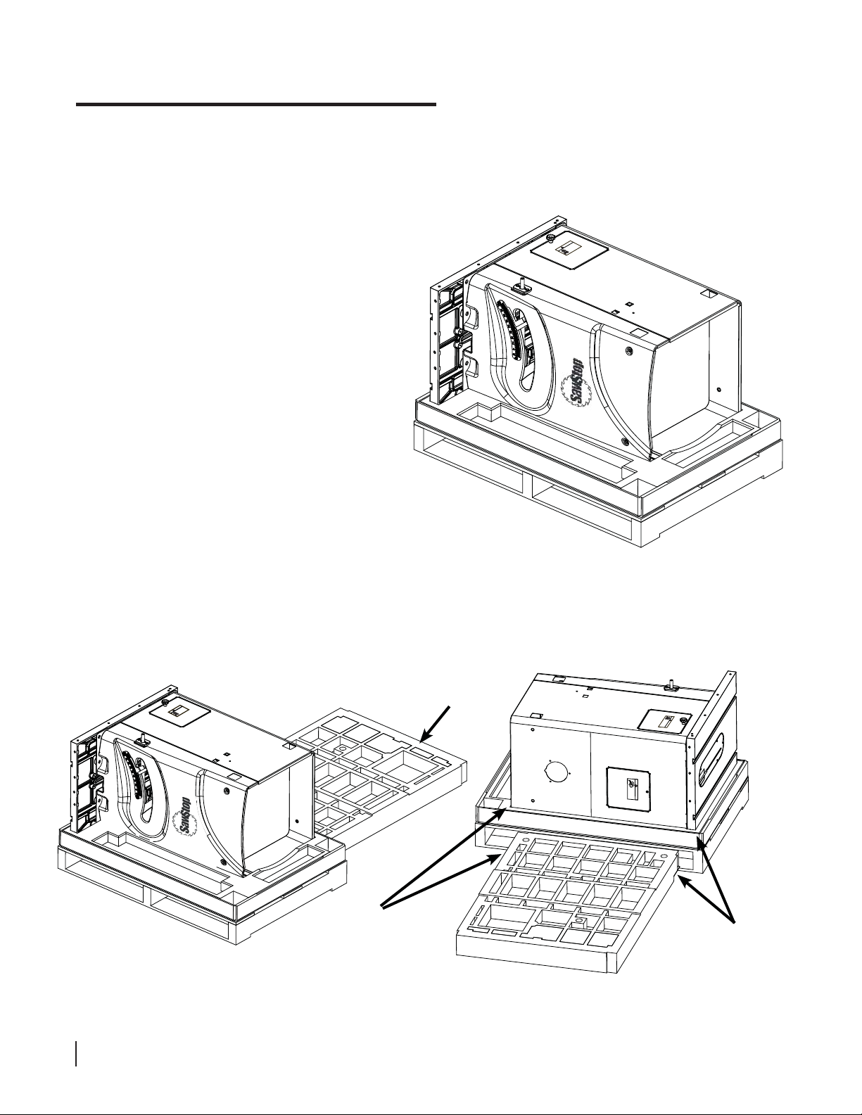
Standing Up Your Saw
1. Your saw is shipped horizontal to protect it from tipping during transit. To stand up your saw, fi rst remove all
packing materials and accessories from the shipping pallet (see Fig. 1). There is a poster that ships with the
saw that shows where all of the accessories are located in the packaging.
h it inside
uc
to
WARNING
ou
y
!
not operate with door open.
.
njury if
i
Do
sh
cru
The blade can retract and cause
or
h
a severe
the cabinet. Also, moving parts can
ut, pinc
c
Fig. 1
2. Take the top piece of Styrofoam and place one of its short sides next to the pallet by the back of the saw, as
shown in Fig 2a. Place the Styrofoam so that the top edge of the table and the bottom edge of the saw both
overhang the edges of the Styrofoam (see Fig. 2b).
top piece of
door open.
ts can
with
uch it inside
ar
o
p
t
g
WARNING
retract and cause
perate
!
t o
no
.
Do
ush
The blade can
cr
a severe injury if you
the cabinet. Also, movin
cut, pinch or
the bottom edge
of the saw should
overhang the edge
of the Styrofoam
Styrofoam
cut, pin
the ca
a severe
The blade can retract
!
D
o n
WARNING
ot
b
c
inet. Also,
h or crus
o
injury if you touch it in
perate wit
h
mov
.
h
door o
in
and cause
g parts can
pen.
side
!
WARNING
door ope
Do not ope
can pinch,
Moving gea
n.
cut or crush
rate with
rs and parts
.
the edge of the
table should
overhang the edge
of the Styrofoam
Fig. 2a
16 SawStop 10” Professional Cabinet Saw
Fig. 2b
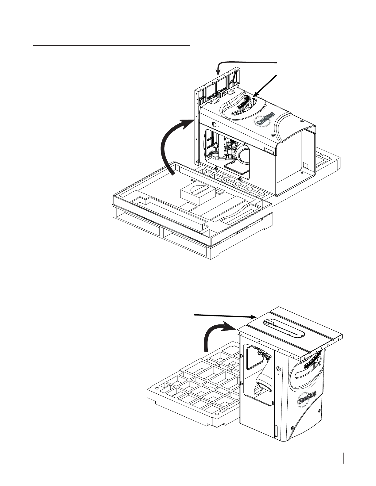
Standing Up Your Saw
3. With the help of another person, carefully roll the saw
off the pallet and onto the top piece of Styrofoam, as
shown in Fig. 3. You can use the cast iron table and
the elevation control shaft as lifting points to help
you roll the saw. Wear safety gloves and be careful
to use proper lifting technique to avoid injury.
use the table and the
elevation control shaft
as lifting points to help
roll the saw
Fig. 3
If you have a Professional Cabinet Saw Mobile Base ...
install it now while the saw is on its side. Refer to the manual that comes with your Professional Cabinet Saw
Mobile Base for instructions. Once the mobile base is installed, continue with step 4 to stand up your saw.
4. With the help of another person,
carefully tip the saw to the
upright position by lifting under
the rear edge of the cast iron
table (see Fig. 4). Lift the saw
slowly so that it slides off the
Styrofoam and onto the fl oor
without damaging the cabinet.
lift under the rear
edge of the table
Fig. 4
SawStop 10” Professional Cabinet Saw 17
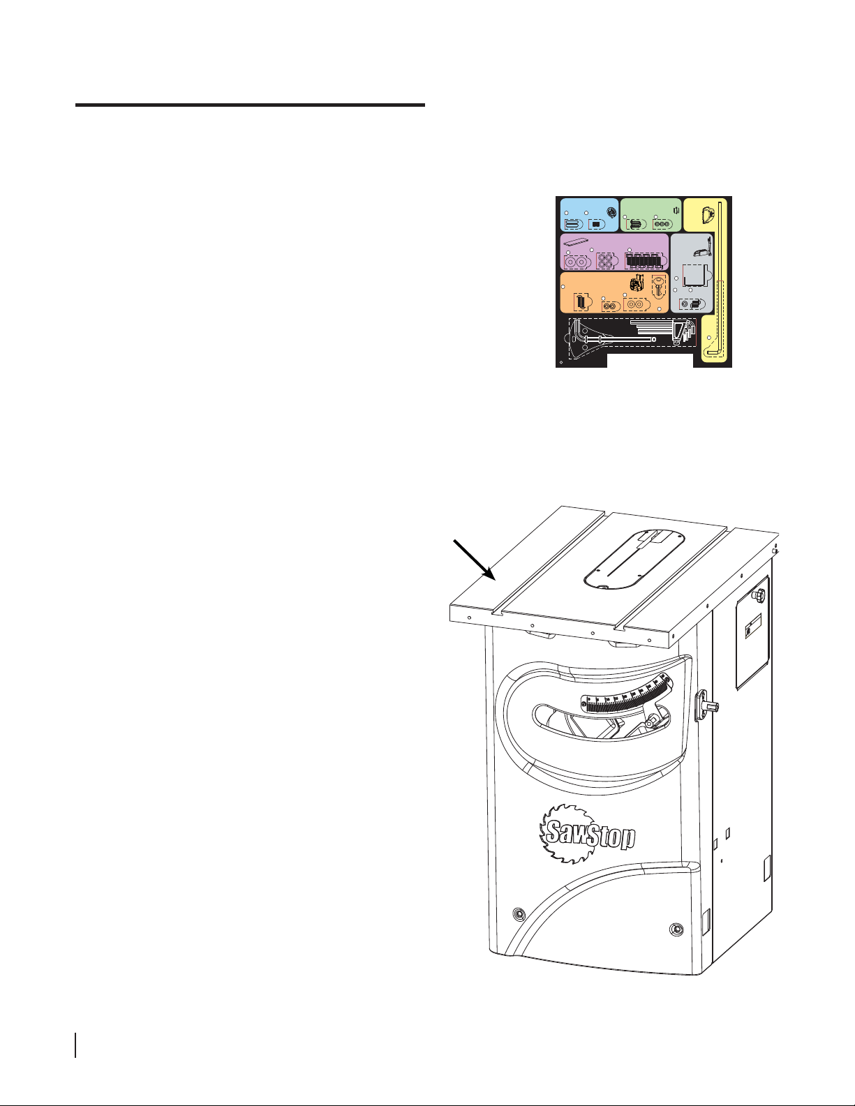
Assembling Y our Saw
The instructions to assemble your Professional Cabinet Saw are listed below. In addition to the tools included
with the Table Saw Hardware Pack (shown in Fig. 5 below) you will also need the following tools to complete the
assembly:
Installing the Handwheels
Hardware for Steps 2-3
1
• a Phillips screwdriver
Keys,
5 x 5 x 25 (2)
• a 13 mm wrench
• a 14 mm wrench
• a level or straight edge
Washers,
6
M8 (8)
Mounting the Switch Box
9
Button Head Socket Screws,
M6 x 20 (2)
F
1. Once the saw is in the upright position, remove the plastic covering from the cast iron table top and remove
the yellow label from the top of the table insert. Wipe the oil off the table top with a soft, clean cloth (see
Fig. 6). Do the same for the extension wings. The table top and extension wings are shipped with a coating of
oil to prevent the cast iron from rusting.
Mounting the Dust Port
2
Set Screws,
Button Head Screws,
M6 x 8 (2)
M5 x 3 x 15 (3)
3
Mounting the Extension Wings
Hardware for Step 6
8
7
Lock Washers, M8 (8)
Hex Bolts, M8 x 16 (8)
Hardware for Step 7
Lock Washers,
M6 (2)
10
Blade Spacing
Adjustment Gauge (1)
Tools
11
Hex Key, M8 (1)
Washers, M6 (2)
Fig. 5
Hardware for Step 4
Lock Washers,
M5 (3)
4
Mounting the
Wrench & Tool
Holders
Blade
Wrench
Holder
13
14
Washers,
M6 (2)
Switch Box
Keys (2)
12
Hex Keys: M3 (1), M4 (1), M5 (1), M6 (1)
Mounting
the
Motor
Cover
Hardware for Step 5
Hardware for Step 8
15
Lock
Button Head
Screws,
M6 x 12 (2)
Motor
Cover
Rod
5
NOTE: Before assembling the saw,
make sure that all packaging has been
removed and all parts unpacked.
In particular, DO NOT PROCEED with
the assembly of the saw until the switch
box has been moved to the outside of
the cabinet. (See unpacking poster).
When unpacking the switch box
assembly , be careful not to damage the
power cord or the cords attached to the
switch box when cutting the cable ties.
Be sure to remove all cardboard pieces
from the inside of the cabinet.
wipe the table top with
a soft, clean cloth
WARNING
!
Do not operate with door open.
The blade can retract and cause
a severe injury if you touch it in
the cabinet. Also, moving parts can
cut, pinch or crush.
side
18 SawStop 10” Professional Cabinet Saw
Fig. 6
Assembling Y our Saw
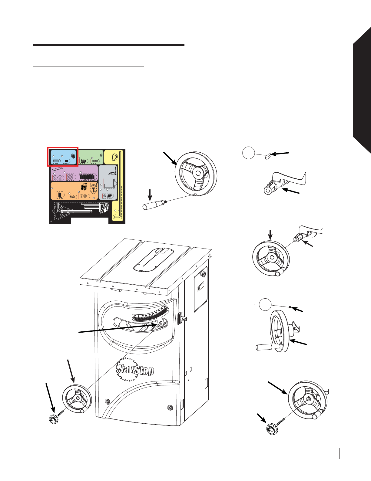
Installing the Elevation Handwheel
2. Open one of the handwheel packages included with your saw and screw the handle into the handwheel (see
Fig. 7). Tighten the handle with a 14 mm wrench. The hardware required to install the elevation handwheel is
located in the area with the blue background on the Table Saw Hardware Pack. Remove a key from the Table
Saw Hardware Pack and insert it into the slot at the end of the elevation control shaft (see Fig. 8). Slide the
handwheel onto the end of the elevation control shaft (see Fig. 9) until the face of the handwheel is fl ush with
the end of the shaft. Remove a set screw from the Table Saw Hardware Pack and insert it into the small hole
located on the side of the handwheel (see Fig. 10). Use a 3 mm hex key to fully tighten the set screw. Locate
the lock knob with the longer shaft. Screw the lock knob into the end of the elevation control shaft (see Fig. 1 1),
but don’t tighten it completely . The lock knob is used to prevent the handwheel from turning after the blade has
been set to a new elevation.
Assembling Your Saw
Installing the Handwheels
Hardware for Steps 2-3
1
2
Keys,
Set Screws,
5 x 5 x 25 (2)
M6 x 8 (2)
Mounting the Extension Wings
7
Lock Washers, M8 (8)
Washers,
6
M8 (8)
Mounting the Switch Box
Hardware for Step 7
9
Button Head Socket Screws,
M6 x 20 (2)
Lock Washers,
10
Blade Spacing
Adjustment Gauge (1)
Tools
F
Mounting the Dust Port
Button Head Screws,
M5 x 3 x 15 (3)
3
Hardware for Step 6
Washers, M6 (2)
11
M6 (2)
Hex Key, M8 (1)
Hardware for Step 4
Lock Washers,
M5 (3)
4
8
Hex Bolts, M8 x 16 (8)
Switch Box
Keys (2)
12
Hex Keys: M3 (1), M4 (1), M5 (1), M6 (1)
Mounting
the
Motor
Cover
Hardware for Step 5
Mounting the
Wrench & Tool
Holders
Hardware for Step 8
Blade
Wrench
Holder
13
15
14
Lock
Washers,
M6 (2)
Button Head
Screws,
M6 x 12 (2)
handwheel
1
key
handle
elevation
control shaft
Motor
Cover
Rod
5
Fig. 7
Fig. 8
handwheel
elevation
control shaft
en.
de
ith door op
WARNING
!
Do not operate w
The blade can retract and cause
a severe injury if you touch it insi
the cabinet. Also, moving parts can
cut, pinch or crush.
Fig. 9
2
set screw
elevation
control shaft
elevation
lock knob
handwheel
Fig. 12
handwheel
Fig. 10
handwheel
elevation
lock knob
Fig. 11
SawStop 10” Professional Cabinet Saw 19
Assembling Y our Saw
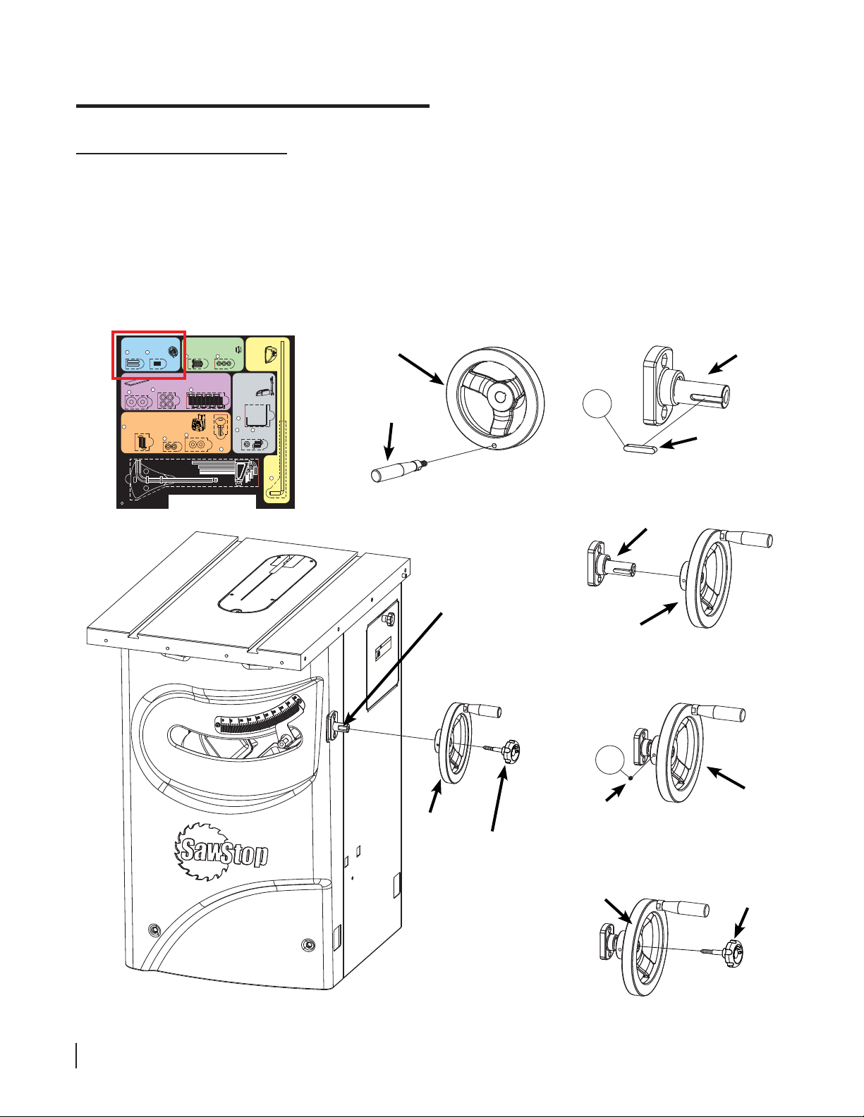
Installing the Tilt Handwheel
3. Open the other handwheel package and screw the handle into the handwheel (see Fig. 13). Tighten the handle
with a 14 mm wrench. The hardware required to install the tilt handwheel is located in the area with the blue
background on the Table Saw Hardware Pack. Remove a key from the Table Saw Hardware Pack and insert it
into the slot at the end of the tilt control shaft (see Fig. 14). Slide the handwheel onto the end of the tilt control
shaft (see Fig. 15) until the face of the handwheel is fl ush with the end of the tilt control shaft. Remove a set
screw from the Table Saw Hardware Pack and insert it into the small hole located on the side of the handwheel
(see Fig. 16). Use a 3 mm hex key to fully tighten the set screw. Locate the lock knob with the shorter shaft.
Screw the lock knob into the end of the tilt control shaft (see Fig. 17), but don’t tighten it completely. The lock
knob is used to prevent the handwheel from turning after the blade has been set to a new tilt angle.
Installing the Handwheels
Hardware for Steps 2-3
1
2
Keys,
Set Screws,
5 x 5 x 25 (2)
M6 x 8 (2)
Mounting the Extension Wings
7
Lock Washers, M8 (8)
Washers,
6
M8 (8)
Mounting the Switch Box
Hardware for Step 7
9
Button Head Socket Screws,
M6 x 20 (2)
Lock Washers,
10
Blade Spacing
Adjustment Gauge (1)
Tools
F
Mounting the Dust Port
Button Head Screws,
M5 x 3 x 15 (3)
3
Hardware for Step 6
8
Washers, M6 (2)
11
M6 (2)
Hex Key, M8 (1)
Hardware for Step 4
Lock Washers,
M5 (3)
4
Hex Bolts, M8 x 16 (8)
Switch Box
Keys (2)
12
Hex Keys: M3 (1), M4 (1), M5 (1), M6 (1)
Mounting
the
Motor
Cover
Hardware for Step 5
Mounting the
Wrench & Tool
Holders
Hardware for Step 8
Blade
Wrench
Holder
13
15
14
Lock
Washers,
M6 (2)
Button Head
Screws,
M6 x 12 (2)
handwheel
tilt control
shaft
handle
1
key
Motor
Cover
Rod
5
Fig. 13
Fig. 14
tilt control
shaft
tilt control
shaft
handwheel
WARNING
!
Do not operate with door open.
The blade can retract and cause
a severe injury if you touch it inside
the cabinet. Also, moving parts can
cut, pinch or crush.
Fig. 15
Fig. 18
20 SawStop 10” Professional Cabinet Saw
handwheel
tilt lock
knob
2
set screw
handwheel
handwheel
Fig. 16
tilt lock
knob
Fig. 17
Assembling Y our Saw
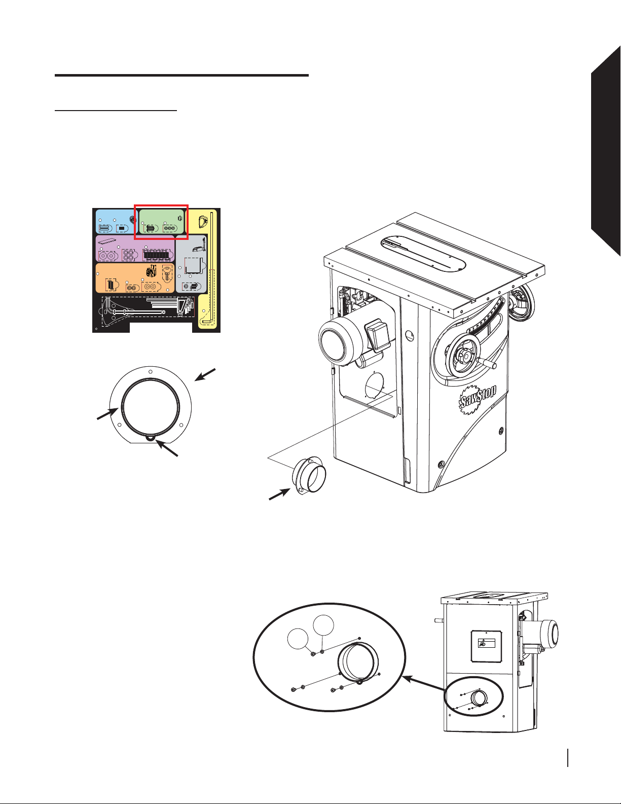
Installing the Dust Port
4. The dust port comes attached to the end of a fl exible hose residing within the cabinet. Notice that there is a
small semicircle on the dust port fl ange (see Fig. 19). The dust port must be inserted into the four inch diameter
hole at the back of the cabinet from the inside of the cabinet as shown in Fig. 20. The semicircle acts as a key to
correctly orient the dust port. The hardware required to install the dust port is located in the area with the green
background on the Table Saw Hardware Pack. Remove the three dust port screws and lock washers from the
Table Saw Hardware Pack and place a lock washer on each screw. Keep the screws nearby.
fl ange
Installing the Handwheels
Hardware for Steps 2-3
1
2
Keys,
Set Screws,
5 x 5 x 25 (2)
M6 x 8 (2)
Mounting the Extension Wings
7
Lock Washers, M8 (8)
Washers,
6
M8 (8)
Mounting the Switch Box
Hardware for Step 7
9
Button Head Socket Screws,
M6 x 20 (2)
Lock Washers,
10
Blade Spacing
Adjustment Gauge (1)
Tools
F
Mounting the Dust Port
Button Head Screws,
M5 x 3 x 15 (3)
3
Hardware for Step 6
8
Hex Bolts, M8 x 16 (8)
Washers, M6 (2)
11
M6 (2)
Hex Key, M8 (1)
Fig. 19
Hardware for Step 4
Lock Washers,
M5 (3)
4
Mounting the
Wrench & Tool
Holders
Hardware for Step 8
Blade
Wrench
Holder
13
14
Lock
Washers,
M6 (2)
Switch Box
Keys (2)
12
Hex Keys: M3 (1), M4 (1), M5 (1), M6 (1)
semicircle
Mounting
the
Motor
Cover
Hardware for Step 5
15
Button Head
Screws,
M6 x 12 (2)
Assembling Your Saw
Motor
Cover
Rod
5
dust
port
dust
port
Fig. 20
Holding the dust port in your hand, reach inside the cabinet through the opening on the side of the cabinet
through which the motor protrudes and fi t the dust port in the hole so that the semicircle fi ts in the cabinet and
the fl ange around the dust port lies fl at against the inside of the cabinet. When correctly installed, the three
holes in the cabinet surrounding the dust port will line up with the three bosses in the dust port.
While holding the dust port fi rmly in
place on the inside of the cabinet,
insert each of the three screws into
the holes surrounding the dust port
on the outside of the cabinet, as
shown in Fig. 21. Using a Phillips
screwdriver, tighten each screw
a little bit at a time until all three
screws are securely in place.
4
WARNING
!
3
Fig. 21
SawStop 10” Professional Cabinet Saw 21
Moving gears and parts
can pinch, cut or crush.
Do not operate with
door open.
Assembling Y our Saw
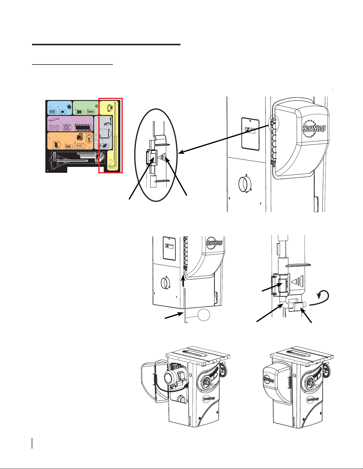
Installing the Motor Cover
5. Locate the motor cover and remove the motor cover rod from the area with the yellow background on the Table
Saw Hardware Pack. Hold the motor cover against the side of the saw over the motor such that the two arrows
on the side of the cover point to the two metal tubes on the side of the cabinet (see Fig. 22).
Installing the Handwheels
Hardware for Steps 2-3
1
Keys,
5 x 5 x 25 (2)
Washers,
6
M8 (8)
Mounting the Switch Box
9
Button Head Socket Screws,
M6 x 20 (2)
F
Mounting the Dust Port
2
Set Screws,
Button Head Screws,
M6 x 8 (2)
M5 x 3 x 15 (3)
3
Mounting the Extension Wings
Hardware for Step 6
8
7
Lock Washers, M8 (8)
Hardware for Step 7
Lock Washers,
M6 (2)
10
Blade Spacing
Adjustment Gauge (1)
Tools
11
Hex Key, M8 (1)
Washers, M6 (2)
Hardware for Step 4
Lock Washers,
M5 (3)
4
Hex Bolts, M8 x 16 (8)
Switch Box
Keys (2)
12
Hex Keys: M3 (1), M4 (1), M5 (1), M6 (1)
Mounting
the
Motor
Cover
Hardware for Step 5
Mounting the
Wrench & Tool
Holders
Hardware for Step 8
Blade
Wrench
Holder
13
15
14
Lock
Washers,
M6 (2)
Button Head
Screws,
M6 x 12 (2)
Motor
Cover
Rod
5
upper tube
on cabinet
Slip the straight end of the motor
cover rod up through the bottom
tube then through the row of halfcylinders along the edge of the
motor cover and fi nally through the
upper tube (see Fig. 23). Rotate the
motor cover rod so that the bent end
of the rod fi ts into the hook on the
motor cover just below the bottom
metal tube (see Fig. 24).
arrow on
motor cover
!
WARNING
Moving gears and parts
can pinch, cut or crush.
Do not operate with
door open.
Fig. 22
!
WARNING
Moving gears and parts
can pinch, cut or crush.
Do not operate with
door open.
lower tube
on cabinet
To open the motor cover press
on the ribbed section on the
front of the motor cover until it
unlatches and swing the cover
away from the cabinet. Reverse
the process to close the cover
(see Fig. 25).
22 SawStop 10” Professional Cabinet Saw
rod
5
rod
Fig. 23 Fig. 24
Fig. 25
hook on
motor
cover
Assembling Y our Saw
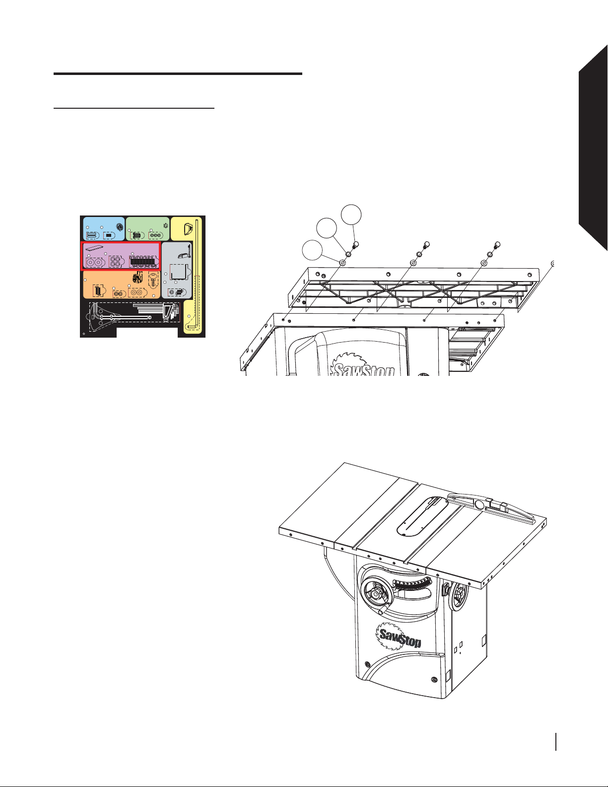
Mounting the Extension Wings
6. The hardware required to mount the cast iron extension wings to the cast iron table top is located in the area
with the purple background on the Table Saw Hardware Pack. Position one of the extension wings next to
the left side of the cast iron table with the chamfer toward the front and align the holes in the side of the wing
with the four threaded holes on the side of the table (see Fig. 26). Mount the left extension wing with four M8
washers, four M8 lock washers and four M8 x 20 hex bolts, but do not tighten. Repeat the same procedure to
mount the other extension wing to the right side of the table.
Installing the Handwheels
Hardware for Steps 2-3
1
Keys,
5 x 5 x 25 (2)
Washers,
6
M8 (8)
Mounting the Switch Box
9
Button Head Socket Screws,
M6 x 20 (2)
F
Mounting the Dust Port
2
Set Screws,
Button Head Screws,
M6 x 8 (2)
M5 x 3 x 15 (3)
3
Mounting the Extension Wings
Hardware for Step 6
8
7
Lock Washers, M8 (8)
Hex Bolts, M8 x 16 (8)
Hardware for Step 7
Washers, M6 (2)
11
Lock Washers,
M6 (2)
10
Blade Spacing
Adjustment Gauge (1)
Hex Key, M8 (1)
Tools
Hardware for Step 4
Lock Washers,
M5 (3)
4
Mounting the
Wrench & Tool
Holders
Hardware for Step 8
Blade
Wrench
Holder
13
14
Lock
Washers,
M6 (2)
Switch Box
Keys (2)
12
Hex Keys: M3 (1), M4 (1), M5 (1), M6 (1)
Mounting
the
Motor
Cover
Hardware for Step 5
15
Button Head
Screws,
M6 x 12 (2)
Motor
Cover
Rod
5
Use a straight-edge to level the extension
wings with the cast iron table top and
tighten all of the M8 x 20 hex bolts with a
13 mm wrench (see Fig. 27).
8
Assembling Your Saw
7
6
Fig. 26
Fig. 27
SawStop 10” Professional Cabinet Saw 23
Assembling Y our Saw
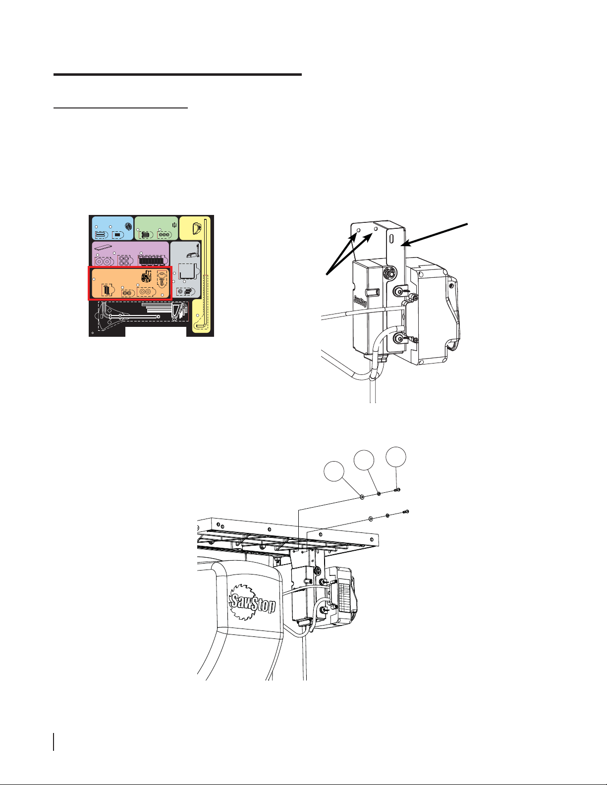
Mounting the Switch Box
7. The hardware required to mount the switch box is located in the area with the orange background on the Table
Saw Hardware Pack. Remove two M6 x 20 button head socket screws, two M6 lock washers and two M6
washers and place a lock washer followed by a washer on the end of each screw. Mount the switch box under
the left extension wing by inserting the screws into the two holes at the upper end of the switch box mounting
bracket (see Fig. 28) and threading them into the holes towards the front of the left extension wing (see
Fig. 29). Tighten the screws with a 4 mm hex key.
Installing the Handwheels
Hardware for Steps 2-3
1
2
Keys,
Set Screws,
5 x 5 x 25 (2)
M6 x 8 (2)
Mounting the Extension Wings
7
Lock Washers, M8 (8)
Washers,
6
M8 (8)
Mounting the Switch Box
Hardware for Step 7
9
Button Head Socket Screws,
M6 x 20 (2)
Lock Washers,
10
Blade Spacing
Adjustment Gauge (1)
Tools
F
Mounting the Dust Port
Button Head Screws,
3
Hardware for Step 6
11
M6 (2)
Hex Key, M8 (1)
Hardware for Step 4
Lock Washers,
M5 (3)
M5 x 3 x 15 (3)
4
8
Hex Bolts, M8 x 16 (8)
Washers, M6 (2)
Switch Box
Keys (2)
12
Hex Keys: M3 (1), M4 (1), M5 (1), M6 (1)
Mounting
the
Motor
Cover
Hardware for Step 5
Mounting the
Wrench & Tool
Holders
Hardware for Step 8
Blade
Wrench
Holder
13
15
14
Lock
Washers,
M6 (2)
Button Head
Screws,
M6 x 12 (2)
switch box
mounting
bracket
mounting
holes
Motor
Cover
Rod
5
Fig. 28
10
9
11
24 SawStop 10” Professional Cabinet Saw
Fig. 29
System Status Codes
• • • • • •
¯
¯
¯
• • • • • •
• • • • • •
¯
¯
¯
¯
¯
¯
SawStop
RedGrn
Status
¯
¯
¯
System Initia
lizing
System Ready
Replace Cartri
dge
Coasting Down
Bypass Mode O
n
Turn Start Swi
• • • • • •
tch
To “Off”
Turn Cartridge
¯
¯
¯
Key To “On”
Close Access
Doors
Adjust Position
of
Brake
Contact Detec
• • • • • •
ted
During Standby
Contact Dete
• • • • • •
cted
During Bypas
s
Overload Due To
• • • • • •
Wet Wood
Assembling Y our Saw
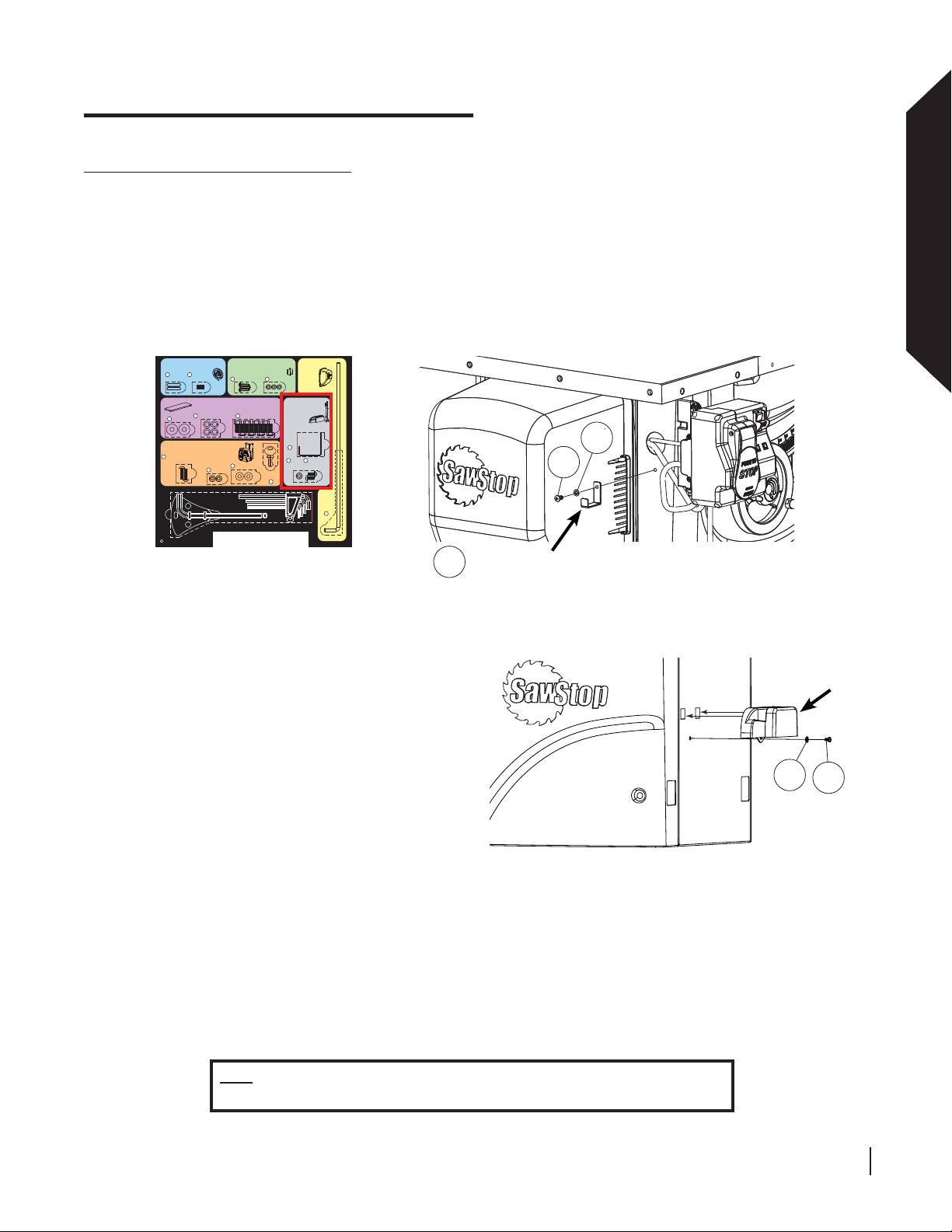
Mounting the Accessory Holders
8. Your saw comes with two tool holders to store saw accessories. The blade wrench holder provides a place to
hang the wrenches that came with your saw. The accessory tool holder provides a place to store your riving
knife, miter gauge and blade guard. The hardware required to mount the two accessory holders is located
in the area with the gray background on the Table Saw Hardware Pack. To mount the blade wrench holder,
remove the blade wrench holder, one M6 x 12 button head screw and one M6 lock washer from the Table Saw
Hardware Pack. Place the lock washer on the screw, insert the screw through the hole in the blade wrench
holder and then thread the screw into the hole on the left side of the cabinet behind the switch box (see Fig. 30)
Tighten the screw with a 4mm hex key.
Installing the Handwheels
Hardware for Steps 2-3
1
Keys,
5 x 5 x 25 (2)
Washers,
6
M8 (8)
Mounting the Switch Box
9
Button Head Socket Screws,
M6 x 20 (2)
F
Mounting the Dust Port
2
Set Screws,
Button Head Screws,
M6 x 8 (2)
M5 x 3 x 15 (3)
3
Mounting the Extension Wings
Hardware for Step 6
8
7
Lock Washers, M8 (8)
Hardware for Step 7
Lock Washers,
10
Blade Spacing
Adjustment Gauge (1)
Tools
Washers, M6 (2)
11
M6 (2)
Hex Key, M8 (1)
Hardware for Step 4
Lock Washers,
M5 (3)
4
Hex Bolts, M8 x 16 (8)
Switch Box
Keys (2)
12
Hex Keys: M3 (1), M4 (1), M5 (1), M6 (1)
Mounting
the
Motor
Cover
Hardware for Step 5
Mounting the
Wrench & Tool
Holders
Hardware for Step 8
Blade
Wrench
Holder
13
15
14
Lock
Washers,
M6 (2)
Button Head
Screws,
M6 x 12 (2)
14
15
Motor
Cover
Rod
5
blade wrench holder
13
Assembling Your Saw
To install the accessory tool holder, locate the
accessory tool holder and remove the
other M6 x 12 button head screw and M6 lock
washer from the Table Saw Hardware Pack.
Place the lock washer on the screw and insert
the screw through the hole at the bottom of the
accessory tool holder. Mount the accessory tool
holder to the cabinet by slipping the ends of
the hooks on the side of the tool holder into the
corresponding slots on the front lower corner of
the right side of the cabinet and threading the
screw into the hole in the cabinet (see Fig. 31).
Tighten the screw with a 4mm hex key.
Congratulations, your saw is now assembled.
Fig. 30
Fig. 31
accessory
tool holder
14
15
Note: Y ou must install a rip fence prior to using the saw . Refer to the manual
accompanying your rip fence for instructions on how to install the fence.
SawStop 10” Professional Cabinet Saw 25
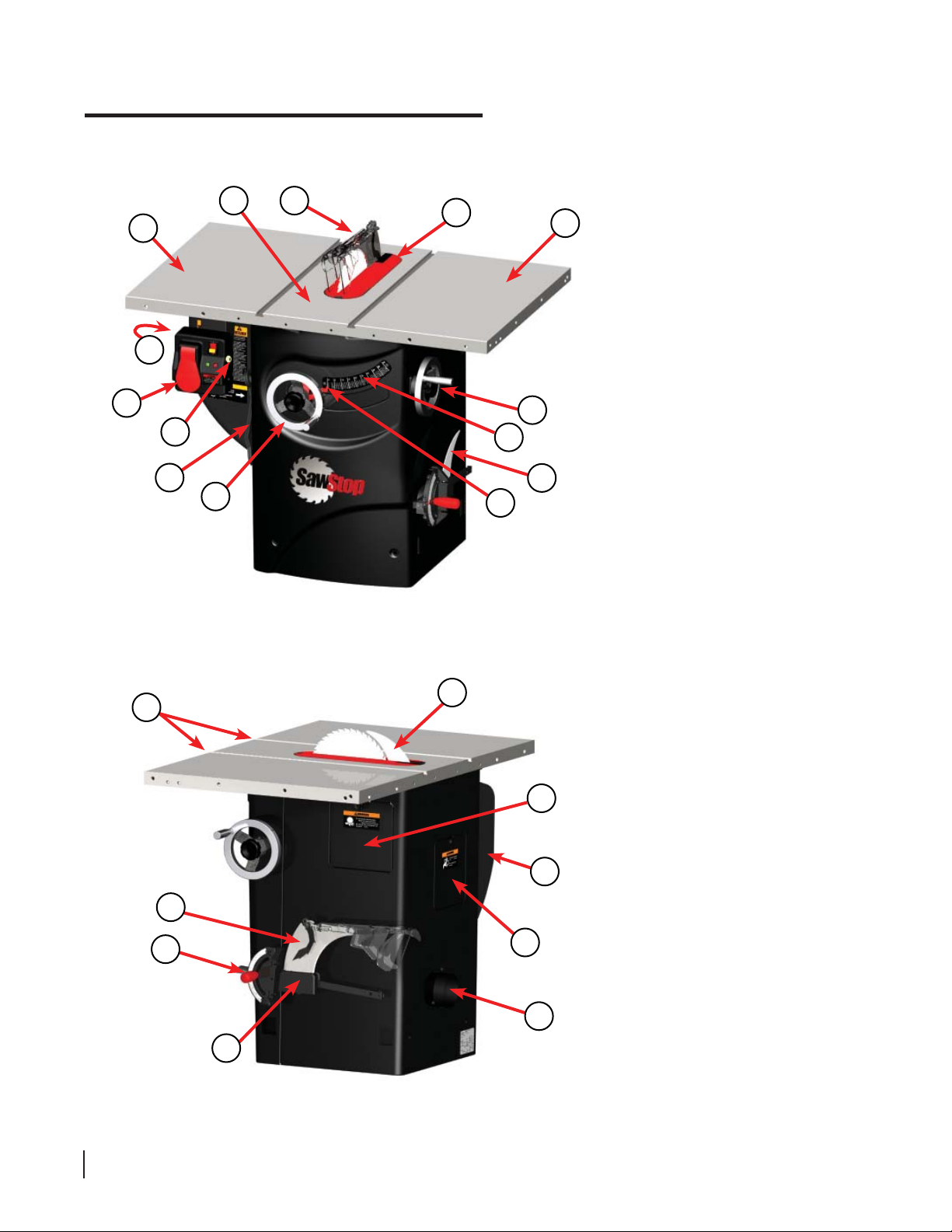
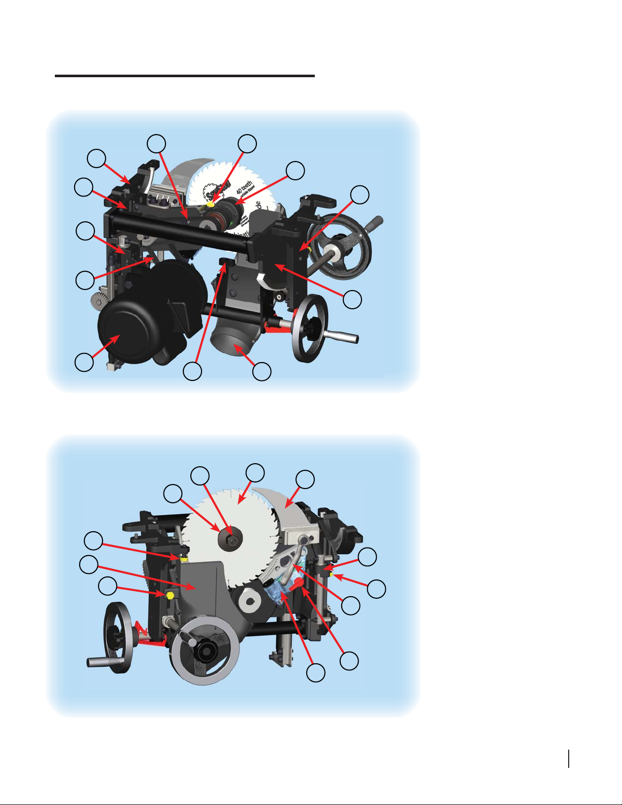
Get to Know Your Saw
The major components of your saw are identifi ed below. Make sure you can identify these components in order
to follow the instructions in this manual.
1
2
3
4
2
11
9
10
12
5
6
8
16
7
Fig. 32
External Components
1. Table Top
2. Extension Wings
3. Blade Guard Assembly
4. Standard Table Insert
5. Elevation Handwheel
6. Tilt Handwheel
7. Tilt Angle Indicator
8. Tilt Angle Scale
14
13
9. Switch Box
16
17
10. Bypass Key
11. Thermal Overload Switch
12. Blade Wrenches (2)
13. Miter Gauge
14. Miter Gauge Slots
15. Accessory Tool Holder
16. Riving Knife
18
17. Side Access Panel
3
20
18. Motor Cover
19. Dust Port
20. Rear Access Panel
19
15
Fig. 33
26 SawStop 10” Professional Cabinet Saw
Get to Know Your Saw
24
25
27
26
23
28
31
30
Fig. 34
40
29
22
21
Internal Components
21. Front Trunnion Bracket
22. Front Trunnion
23. Rear Trunnion Bracket
24. Rear Trunnion
25. Elevation Plate
26. Motor
27. Motor Belt
28. Arbor Belt
29. Arbor Block
30. Brake Positioning Bolt
31. Arbor Bumper
39
43
42
36
35
Fig. 35
32
33
37
34
38
25
32. Saw Blade
33. Riving Knife
34. Quick-Release Clamp Handle
35. Arbor Nut
36. Arbor Washer
37. Brake Cartridge
38. Cartridge Key
39. Dust Shroud
41
40. Dust Port
41. Upper Elevation Limit Stop
42. 0º Tilt Limit Stop
43. 45º Tilt Limit Stop
SawStop 10” Professional Cabinet Saw 27
Preparing Your Saw for Use
Saw Placement
Position the saw on a level surface away from sources of moisture and electrical noise. Make sure there is
suffi cient room to allow free access to all sides of the saw.
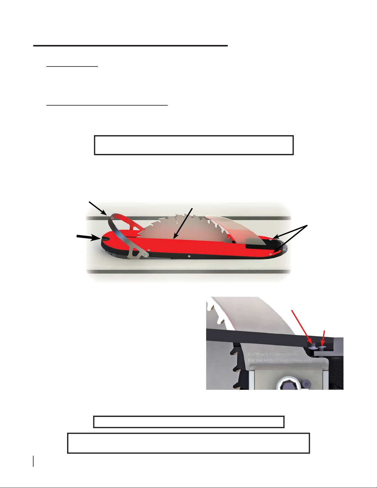
Table Insert Removal and Installation
Y our saw is shipped with a high-quality, zero-clearance table insert. The insert is factory-adjusted to fi t securely
in the table opening and below the table surface. If you wish to perform additional adjustment on the insert,
see page 77 for instructions.
WARNING! Always turn off the main power switch and unplug the power
cord before removing or installing the table insert on your saw.
The rear of the table insert is held in place by two lock-down screws in the bottom rear of the insert and two
lock-down screws in the table opening. It is held down in the front by latches formed at the ends of a rotating
lock-down lever. The lock-down lever allows you to easily remove the insert without the use of tools.
lock-down lever
To install the table insert, hold it at a slight angle, with
the lock-down lever rotated upwards and the rear of
the insert lower than the front (see Fig. 36). Slide the
rear of the insert around the spreader or riving knife
and against the back of the table opening so that the
heads of the rear lock-down screws in the bottom of the
insert slide under the heads of the lock-down screws
in the table opening (see Fig. 37). Then, with the lockdown lever rotated upwards, lower the front end of the
insert into the table opening until the insert lies fl at.
Finally, rotate the lock-down lever all the way down so
that it fi ts along the edge of the table insert. Be certain
that no part of the table insert extends up beyond the
table surface; it should be fl ush or just below the table
surface.
hold insert at a slight angle to table
when installing or removing
Fig. 36
rear
lock-down
screws
rear lock-down
screw in insert
rear lock-down
screw in table
opening
Fig. 37
WARNING! Never operate the saw without the table insert in place.
CAUTION! Do not use table inserts with metal or other electrically-conductive parts that
could contact the blade. This can cause the brake to be activated unnecessarily.
28 SawStop 10” Professional Cabinet Saw
 Loading...