

Page 1

Infinity &
Infinity HD
RESIDENTIAL ELEVATORS
Planning Guide
Applicable Codes:
ASME A17.1/CSA-B44
Safety Code for Elevators and Escalators
Section 5.3 – Private Residential Elevators
Part No. 000783
24-m09-2015
2015 Savaria Corporation
Page 2

Copyright 2015 Savaria Corporation
All Rights Reserved
Printed in Canada
Page 3

Purpose of this guide
This planning guide is designed to assist architects, contractors and lift professionals in planning for an
Infinity/Infinity HD Residential Elevator to meet the requirements of the following codes:
• ASME A17.1/CSA B44 2000, Section 5.3
• ASME A17.1/CSA B44 2004, Section 5.3
• ASME A17.1 2004, Addendum 2005, Section 5.3
• ASME A17.1/CSA B44 2007, Section 5.3
• ASME A17.1/CSA B44, Addendum 2008, Section 5.3
• ASME A17.1/CSA B44 2010, Section 5.3
• ASME A17.1/CSA B44 2013, Section 5.3
• ASME A17.1 1996, Part 5
We strongly recommend that you contact the code authority having jurisdiction in the area where the lift
will be installed to become familiar with all the legal requirements governing the installation and use of lifts
in commercial applications. It is extremely important for you to know and adhere to all regulations
pertaining to the installation and use of lifts.
How to use this guide
1 Determine your client’s intended use of the lift.
2 Determine the local code requirements.
3 Determine the site installation parameters.
4 Determine the cab type and hoistway size requirements.
NOTE: If the Infinity/Infinity HD also has Auto Slim Doors, do not refer to the tables on pages 6 and 7; refer
instead to Appendix A.
5 Plan for machine room and electrical requirements.
History
January 10, 2011 - Initial release
February 23, 2011
• Added note to step 4 above, under “How to use this guide”
• Added “Auto slim doors” to “Options” in specification table on page 5
• Added IMPORTANT note on page 10 and pages 12 through 23
• Condensed drawings to two per page to reduce book size (pages 12 through 23)
• Added Appendix A with Auto Slim Doors planning information
April 19, 2011 - Updated Auto Slim Door entrance assembly and elevation drawings in Appendix A
August 12, 2011 - Revised Auto Slim Door entrance assembly drawings in Appendix A
September 15, 2011 - Revised Auto Slim Door entrance assembly drawings in Appendix A
August 30, 2012 - Revised Auto Slim Door elevation and plan view drawings in Appendix A
November 6, 2012 - Added door recommendation on page 31
July 9, 2013 - Added Noise Level to specifications table on page 5
March 12, 2014 - Revised specifications table on page 5
November 5, 2014 - Revised Applicable Codes on page 3
December 9, 2014 - Revised all drawings on pages 12 to 23 and in Appendix A on pages 46, 48, 50, 52, 54, and 56
May 25, 2015 - Revised tables on page 42
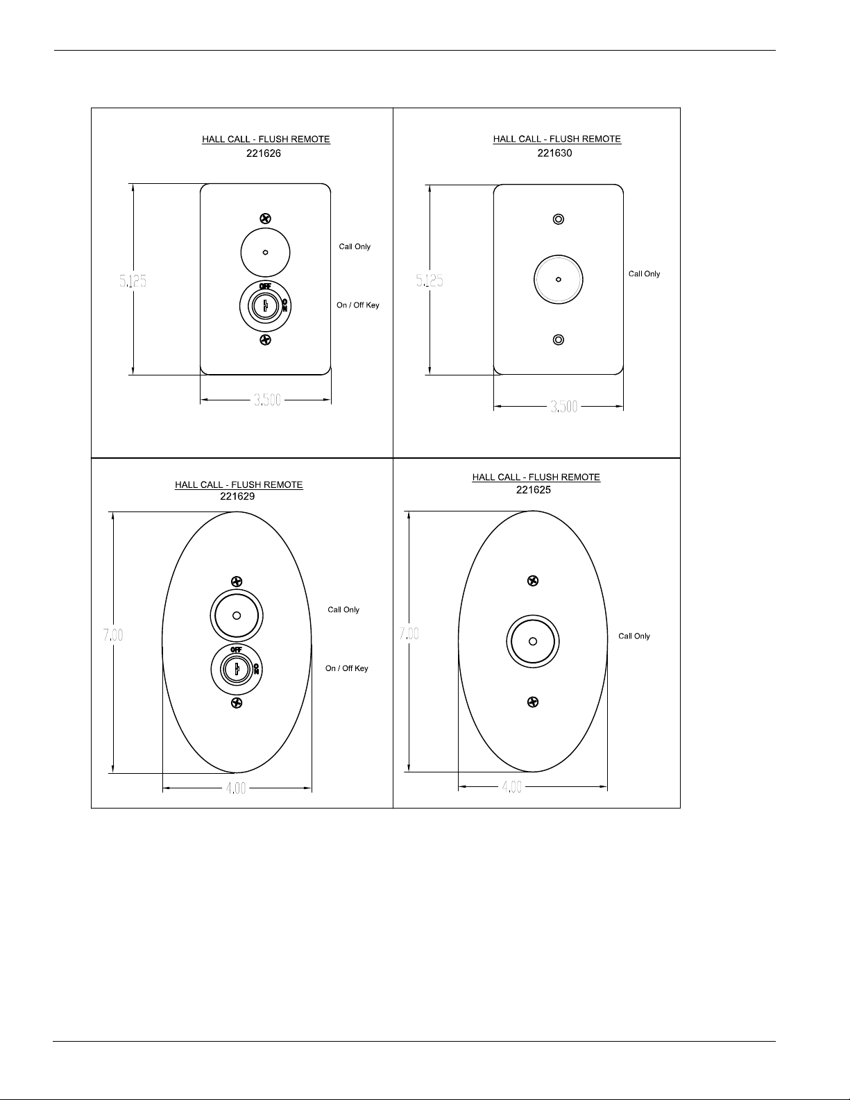
August 7, 2015 - Added COP and Hall Call dimensions on pages 43 and 44
August 31, 2015 - Revised load capacity in specs table on page 5
September 24, 2015 - Added Daily Cycle to specs table on page 5
3
IMPORTANT NOTICE
This Planning Guide provides nominal dimensions and specifications useful for the initial planning of a
project. Before beginning actual construction, make sure you have the installation (shop) drawings
customized with specifications and dimensions for your specific project.
Lift configurations and dimensions are in accordance with our interpretation of the standards set forth by
the codes listed on the front cover of this Planning Guide. Please consult Savaria or the authorized Savaria
dealer in your area for more specific information pertaining to your project, including any discrepancy
between referenced standards and those of any local codes or laws.
The dimensions and specifications in this Planning Guide are subject to change (without notice) due to
product enhancements and continually evolving codes and product applications.
Visit our website www.savaria.com for the most current Infinity drawings and dimensions.
Part No. 000783, 24-m09-2015 Infinity and Infinity HD Planning Guide
Page 4

4
Cab
Cab operating panel
(COP)
Overhead
clearance
Hydraulic cylinder
Guide rails
Aircraft cables
INFINITY IN HOISTWAY
Product description 1-
Meets Americans with Disabilities Act (ADA) requirements
The Infinity and Infinity HD meet the requirements of the ADA Accessibility Guidelines as a means
to provide public building access.
Design assistance
With over 30 years of experience. Savaria has the expertise to provide solutions to practically
every design challenge you face. Please call our Customer Service Department for professional
advice at (800) 661-5112 or (905) 791-5555.
Infinity and Infinity HD Planning Guide Part No. 000783, 24-m09-2015
Page 5

Infinity/Infinity HD specifications 2-
Specification type Specification data
Load capacity Infinity: 750 lb (341 kg), 950 lb (431 kg) or 1000 lb (454 kg)
Rated speed 36 ft/min (0.18 m/s) nominal
Maximum travel 50 ft (15.24 m) – confirm with local code
Maximum # of stops 6 stops
Pit depth required Infinity: 8” (203 mm) minimum up to 96” (2438 mm)
Minimum overhead clearance 92” (2337 mm) for standard 80” cab; 96” (2438 mm) for 84” cab, 108” (2743 mm) for 96” cab
Power supply (circuit to be supplied by others)
NOTE: Amperage may vary depending on
individual units. Verify requirements prior to
installation of power supply.
Lighting supply (circuit to be supplied by
others)
Motor Infinity: 3 HP (2.24 kW)
Drive system 1:2 cable hydraulic
Control system Automatic user interface
Noise level (for typical installation) 74.0 dBA; measured at a height of 1m, distance of 1m, in front of tank, in closed machine room
Daily cycle Normal: 30
Cab size Infinity Type 1L, 1R, 2, 3, 4, and 5:
Cab panel finish Solid melamine or MDF panels (standard)
Hall call station and control panel finish Clear or bronze anodized aluminum (standard)
Standard features Anti-creep device
Options 84” (2133 mm) or 96” (2438 mm) high cab
Infinity HD: 1400 lb (635 kg)
Infinity HD: 12” (305 mm) minimum up to 96” (2438 mm)
North American: 208 volt, three-phase, 30 amps, 60 Hz or 230 volt, single-phase, 30 amps, 60 Hz
NOTE: 60 Amps for Infinity HD
International: 220 volt, single-phase, 40 amps, 50 Hz
North American: 115 volt, 60 Hz, 15 amps
International: 220 volt, 50 Hz 15 amps
Infinity HD: 5 HP (3.73 kW)
Solid state electronics with relay logic motor controls
Heavy: 75
Excessive: 100
Maximum starts in 1 hour on standard installation: 15
NOTE: Please consult your Sales Representative if there a chance you may exceed these amounts.
• 36” x 48” (914 mm x 1219 mm)
• 36” x 54” (914 mm x 1372 mm)
• 36” x 60” (914 mm x 1524 mm)
• 40” x 54” (1016 mm x 1372 mm)
Infinity HD Type 1L, 1R, 2, 3, 4 and 5:
• 48” x 60” (1219 mm x 1524 mm)
Unfinished veneer (optional)
Solid hardwood raised panels (optional)
Stainless steel or brass (optional)
Rectangular (standard) or oval (optional) hall stations, keyless (standard) or keyed (optional)
Alpha-numeric button marking (optional)
Automatic cab on/off lighting
Cab gate safety switch
Car top stop switch
In car digital floor indicator
Clear or bronze anodized aluminum cab entrance trim and handrail
Data plates, capacity tags and rope tags
Emergency stop and alarm buttons
Emergency battery back-up for lighting, alarm and emergency lowering
Upper and lower terminal limits
Magnetic floor selection, stopping and re-levelling
Manual reset slack rope safety switch
Mechanical rail shoring blocks
Negative pressure switch
Pit switch
Pump run timer
Rail sections (8 ft optional or 16 ft standard)
Two 12 V, 4 AH, sealed no maintenance batteries with 24 V, 4 amp Smart Charge™ battery charge
Unfinished plywood sub-floor
Variable speed pressure compensated valve with manual lowering
White ceiling with recessed incandescent down lights
Automatic gate operator (accordion gates only)
Automatic swing door operator
Phone cabinet
Hose with flow control valve (15 ft, 20 ft or 25 ft)
Interlocks for doors by others
Keyed on/off control panel and hall stations
Light screens
Pipe rupture valve
Buffer springs (13” pit depth minimum)
Split cylinder for travel over 384” (9754 mm)
Auto slim doors
5
Part No. 000783, 24-m09-2015 Infinity and Infinity HD Planning Guide
Page 6
6
4YPE,
4YPE2
4YPE
4YPE
4YPE
4YPE
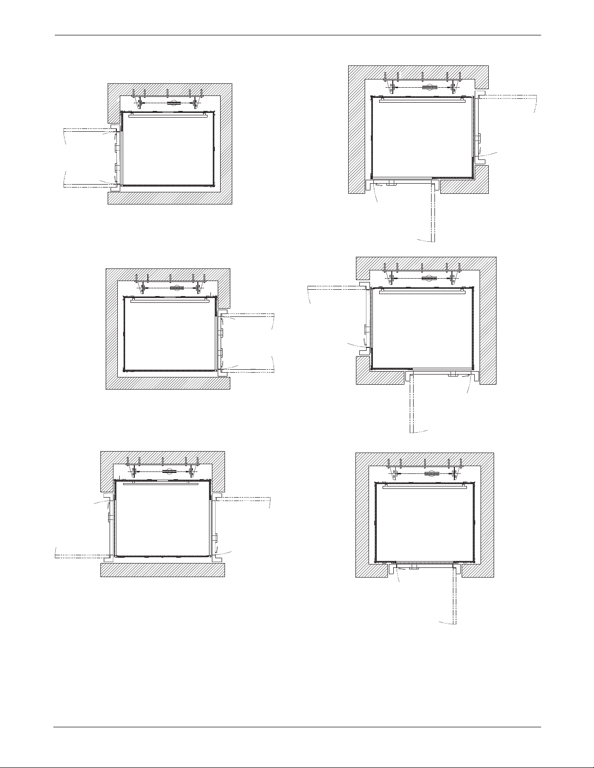
Infinity/Infinity HD cab types 3-
Finished hoistway dimensions must include the drywall. Determine the fire rating of the
IMPORTANT
hoistway, the type and layers of sheet rock and build only off the final installation (shop)
drawings specific to your project.
Infinity and Infinity HD Planning Guide Part No. 000783, 24-m09-2015
Page 7
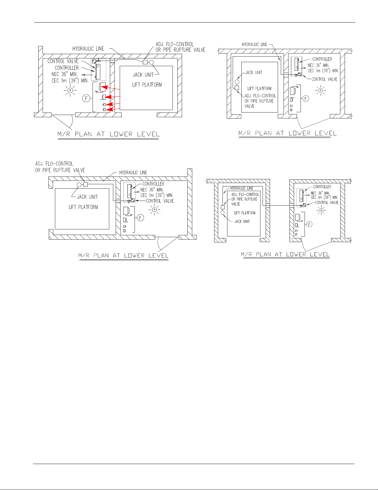
Machine room options 4-
Remote position
Back position
Left-hand position
Right-hand position
230/208V disconnect
115V cab lighting disconnect
Machine room light switch
GFI duplex wall receptacle
7
•The machine room must be built in accordance with local, state/provincial and national codes. Adequate
ventilation is required to maintain a temperature of 50°F to 100°F for output of 3600 BTU per hour.
• Power supply must be 208V three-phase with 30 amp or 230V single-phase with 40 amp dedicated
circuit with equipment ground. A lockable fused disconnect with an auxiliary normally open interlock
switch must be located next to the controller. The electrical circuit must terminate on the line side
terminal lugs of the disconnect. It is provided and installed by others.
• The machine room lighting shall be a minimum of 19 foot candles (204 lux) at working surfaces.
• The switch for the light must be within 18” (457 mm) of the strike side of the machine room door.
• The switch, light and wiring are provided and installed by others. The light must be guarded to prevent
accidental breakage of contact with the hot bulb. The switch, light, wiring and guard are provided and
installed by others.
• A convenience outlet of 115V single-phase 15 amp with G.F.I. shall be located next to the light switch in
the machine room (provided and installed by others).
• A telephone line circuit is to be provided and installed by others. This circuit must be connected to an
outside line or a 24 hour central exchange.
• The machine room access door must be self closing, self locking with a key and spring return latch. Door
and hardware are provided and installed by others. Consult local building codes for door construction.
• The machine room must be free of any pipes, wiring and obstructions not related to the operation of the
lift. Provide a 4 inch conduit from the lift shaft to the remote machine room.
Part No. 000783, 24-m09-2015 Infinity and Infinity HD Planning Guide
Page 8

8
Machine room dimensions 5-
Infinity and Infinity HD Planning Guide Part No. 000783, 24-m09-2015
Page 9
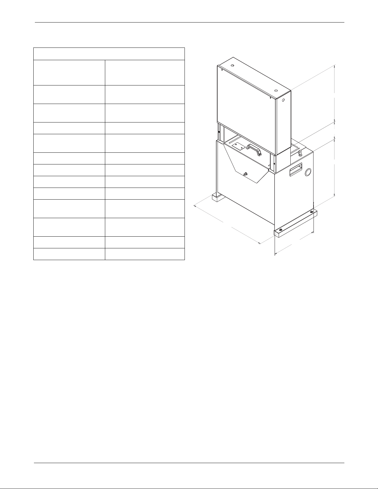
Controller tank specifications 6-
"72.02
"12.6
"93.02
"05.72
"51.61
Controller tank specifications
Height: 47” (1194 mm)
Dimensions
Width: 28” (711 mm)
Depth: 17” (432 mm)
9
Minimum required
clearance
Valve and manual lowering
handle location
Rupture valve test T-fitting factory installed
Tank to controller wiring
Controller layout Relay board
Keyed lock to tank Yes
Machine room required No (with local jurisdiction approval)
Tank capacity (gal/ltr) 15-16.5 gal/57-63 ltr
Maximum dry weight
(lb/kg)
Maximum filled weight
(lb/kg)
Operating environment 50°F - 120°F /10°C - 49°C
Operating volume 57 dBA
39.37” (1000 mm)
Inside tank
Quick connect valve and motor
wiring
147 lb/55 kg
312 lb/117 kg
Controller tank features
• Hydraulic hose connection port on both sides of the
tank
• Built-in handles on both sides of the tank
• Isolation mounting of pump motor valve assembly
minimizes operating issues
Part No. 000783, 24-m09-2015 Infinity and Infinity HD Planning Guide
Page 10
10
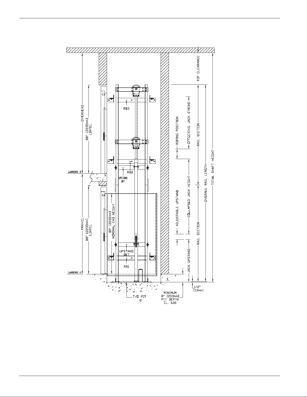
4OPRAILBRACKET2"ATTOPOFHOISTWAYCONSULTYOUR3AVARIAREPRESENTATIVEFOREXACTLOCATION
)NTERMEDIATERAILBRACKET2"INMMINTERVALSABOVEBOTTOMBRACKET
"OTTOMRAILBRACKET2"INMMABOVEPITFLOOR
Elevation view – Infinity 7-
IMPORTANT: Always refer to your plan drawings for dimensions specific to your site.
For Infinity with Auto Slim Doors, DO NOT use the above drawing; refer to Appendix A instead.
Infinity and Infinity HD Planning Guide Part No. 000783, 24-m09-2015
Page 11
11
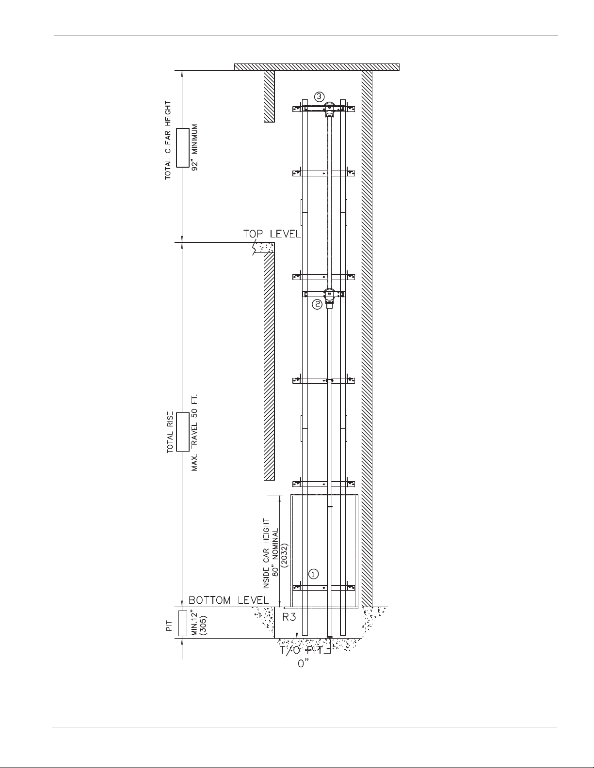
4OPRAILBRACKETATTOPOFHOISTWAYCONSULTYOUR3AVARIAREPRESENTATIVEFOREXACTLOCATION
)NTERMEDIATERAILBRACKETINMMINTERVALSABOVEBOTTOMBRACKET
"OTTOMRAILBRACKETINMMABOVEPITFLOOR
Elevation view – Infinity HD 8-
Part No. 000783, 24-m09-2015 Infinity and Infinity HD Planning Guide
Page 12
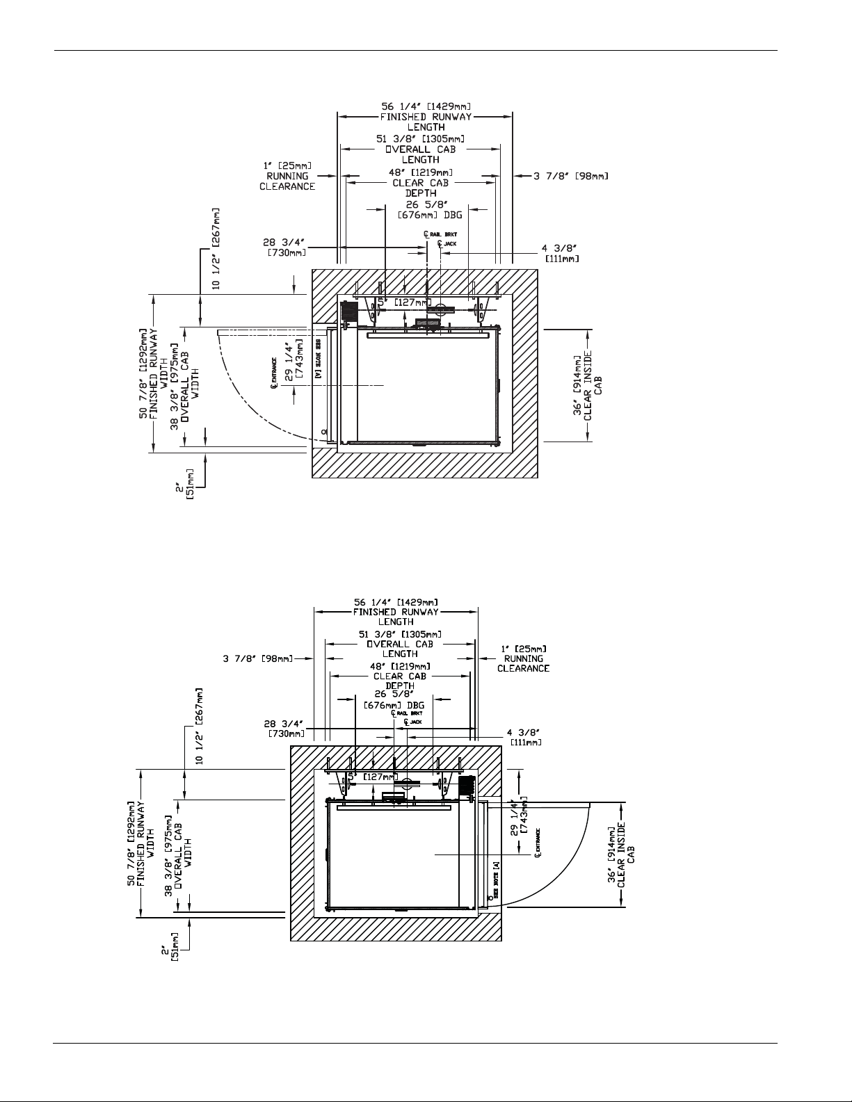
12
Plan view – Infinity 36” x 48” type 1 left-hand 9-
Plan view – Infinity 36” x 48” type 1 right-hand 10-
IMPORTANT: Always refer to your plan drawings for dimensions specific to your site.
For Infinity with Auto Slim Doors, DO NOT use the above drawings; refer to Appendix A instead.
Infinity and Infinity HD Planning Guide Part No. 000783, 24-m09-2015
Page 13
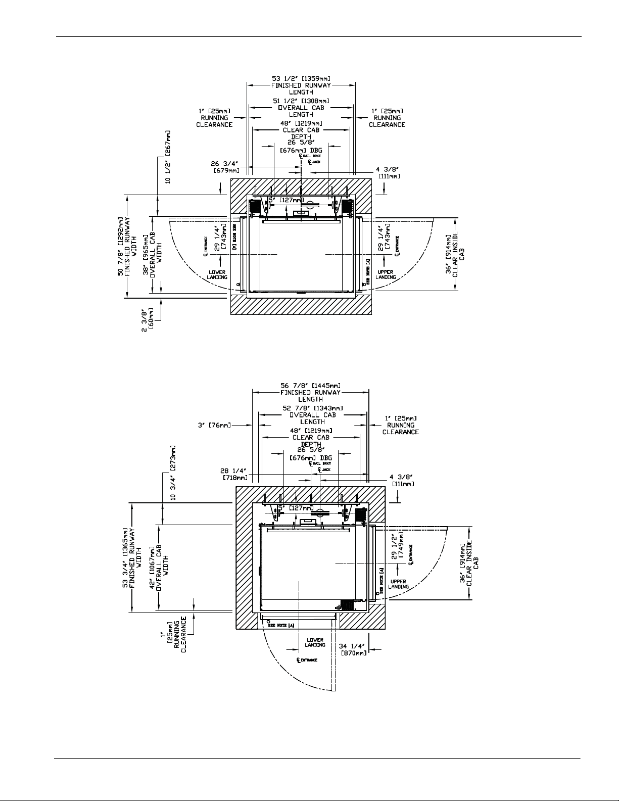
13
Plan view – Infinity 36” x 48” type 2 11-
Plan view – Infinity 36” x 48” type 3 12-
IMPORTANT: Always refer to your plan drawings for dimensions specific to your site.
For Infinity with Auto Slim Doors, DO NOT use the above drawings; refer to Appendix A instead.
Part No. 000783, 24-m09-2015 Infinity and Infinity HD Planning Guide
Page 14
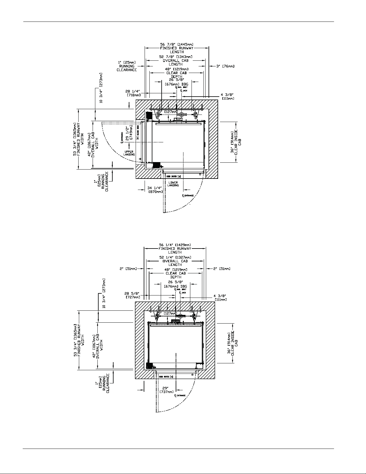
14
Plan view – Infinity 36” x 48” type 4 13-
Plan view – Infinity 36” x 48” type 5 14-
IMPORTANT: Always refer to your plan drawings for dimensions specific to your site.
For Infinity with Auto Slim Doors, DO NOT use the above drawings; refer to Appendix A instead.
Infinity and Infinity HD Planning Guide Part No. 000783, 24-m09-2015
Page 15
15
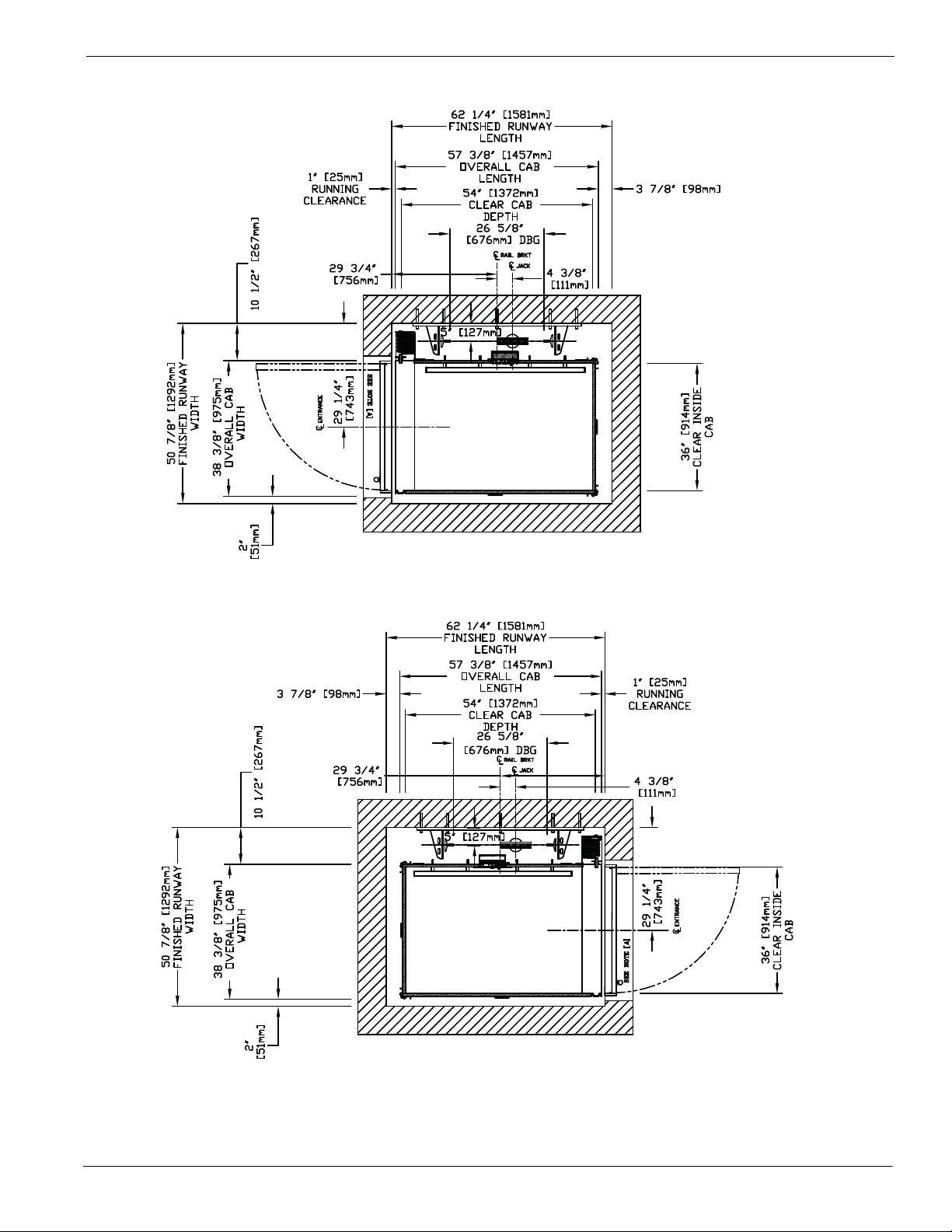
Plan view – Infinity 36” x 54” type 1 left-hand 15-
Plan view – Infinity 36” x 54” type 1 right-hand 16-
IMPORTANT: Always refer to your plan drawings for dimensions specific to your site.
For Infinity with Auto Slim Doors, DO NOT use the above drawings; refer to Appendix A instead.
Part No. 000783, 24-m09-2015 Infinity and Infinity HD Planning Guide
Page 16
16
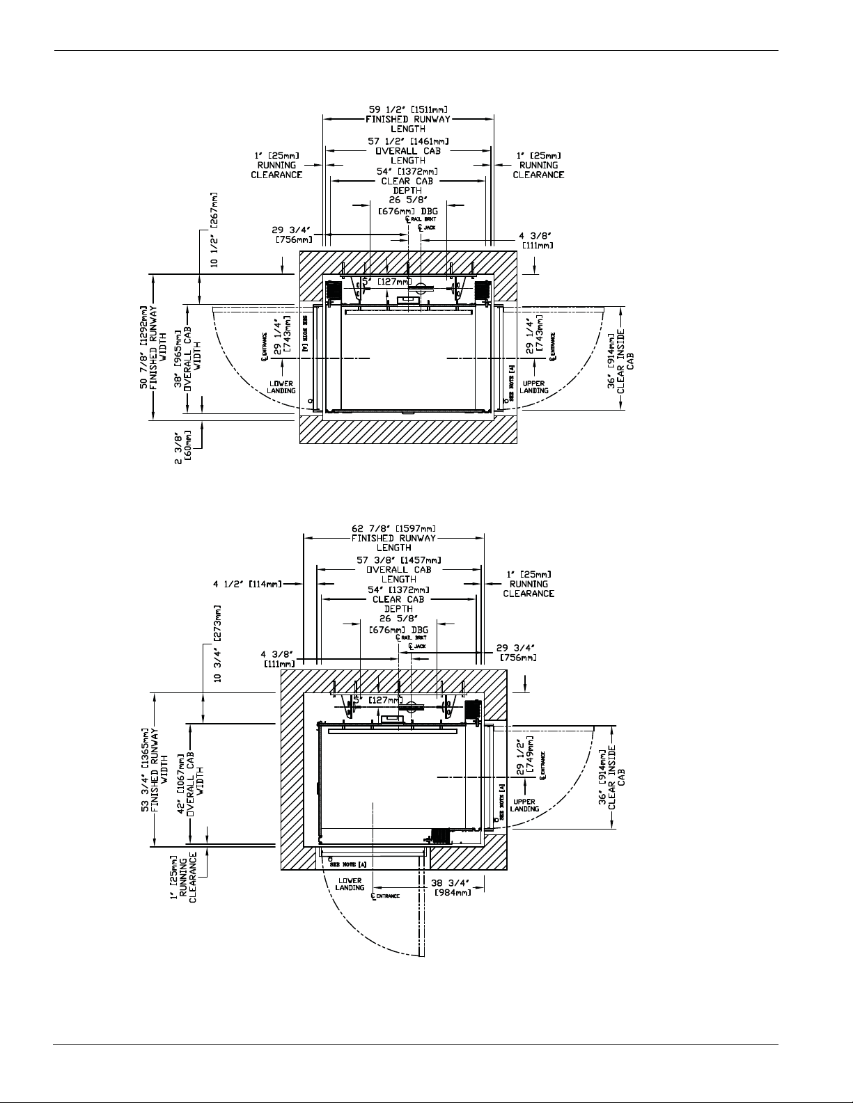
Plan view – Infinity 36” x 54” type 2 17-
Plan view – Infinity 36” x 54” type 3 18-
IMPORTANT: Always refer to your plan drawings for dimensions specific to your site.
For Infinity with Auto Slim Doors, DO NOT use the above drawings; refer to Appendix A instead.
Infinity and Infinity HD Planning Guide Part No. 000783, 24-m09-2015
Page 17
17
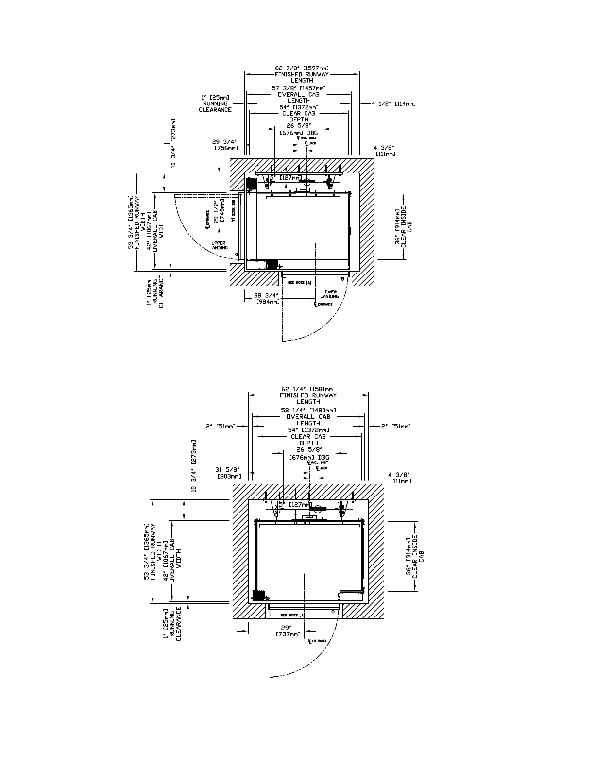
Plan view – Infinity 36” x 54” type 4 19-
Plan view – Infinity 36” x 54” type 5 20-
IMPORTANT: Always refer to your plan drawings for dimensions specific to your site.
For Infinity with Auto Slim Doors, DO NOT use the above drawings; refer to Appendix A instead.
Part No. 000783, 24-m09-2015 Infinity and Infinity HD Planning Guide
Page 18
18
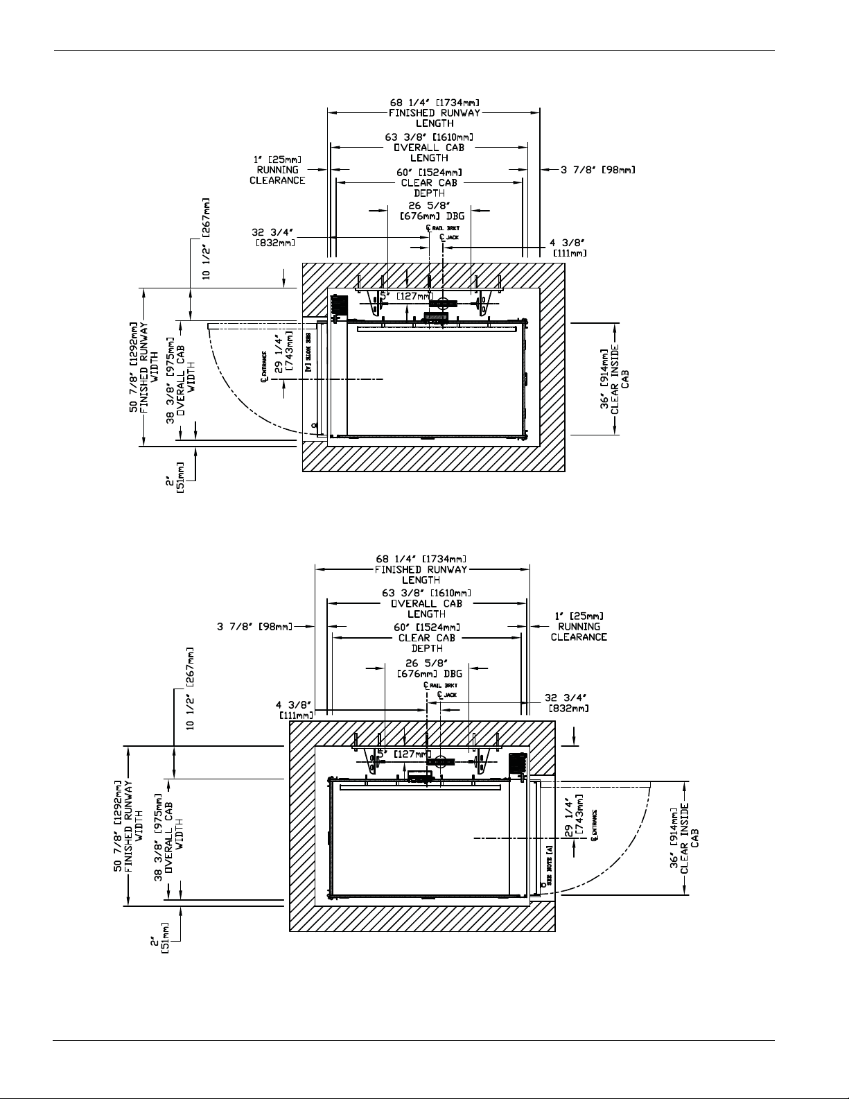
Plan view – Infinity 36” x 60” type 1 left-hand 21-
Plan view – Infinity 36” x 60” type 1 right-hand 22-
IMPORTANT: Always refer to your plan drawings for dimensions specific to your site.
For Infinity with Auto Slim Doors, DO NOT use the above drawings; refer to Appendix A instead.
Infinity and Infinity HD Planning Guide Part No. 000783, 24-m09-2015
Page 19
19
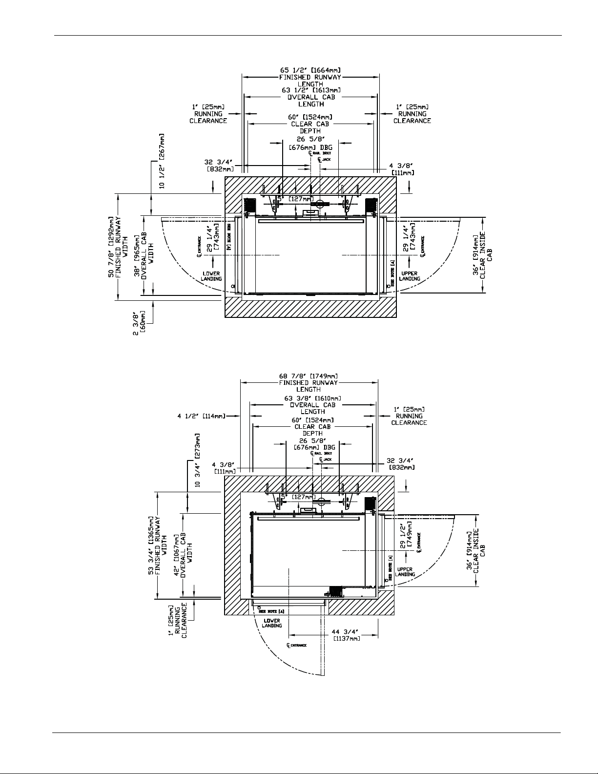
Plan view – Infinity 36” x 60” type 2 23-
Plan view – Infinity 36” x 60” type 3 24-
IMPORTANT: Always refer to your plan drawings for dimensions specific to your site.
For Infinity with Auto Slim Doors, DO NOT use the above drawings; refer to Appendix A instead.
Part No. 000783, 24-m09-2015 Infinity and Infinity HD Planning Guide
Page 20

20
Plan view – Infinity 36” x 60” type 4 25-
Plan view – Infinity 36” x 60” type 5 26-
IMPORTANT: Always refer to your plan drawings for dimensions specific to your site.
For Infinity with Auto Slim Doors, DO NOT use the above drawings; refer to Appendix A instead.
Infinity and Infinity HD Planning Guide Part No. 000783, 24-m09-2015
Page 21
21
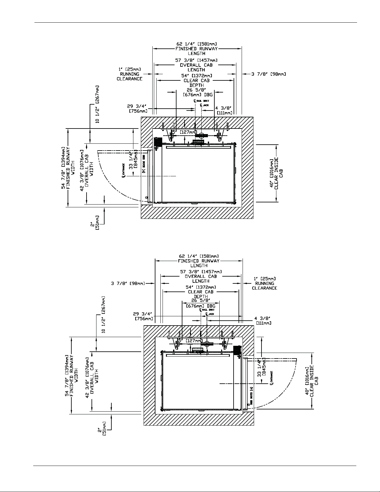
Plan view – Infinity 40” x 54” type 1 left-hand 27-
Plan view – Infinity 40” x 54” type 1 right-hand 28-
IMPORTANT: Always refer to your plan drawings for dimensions specific to your site.
For Infinity with Auto Slim Doors, DO NOT use the above drawings; refer to Appendix A instead.
Part No. 000783, 24-m09-2015 Infinity and Infinity HD Planning Guide
Page 22
22
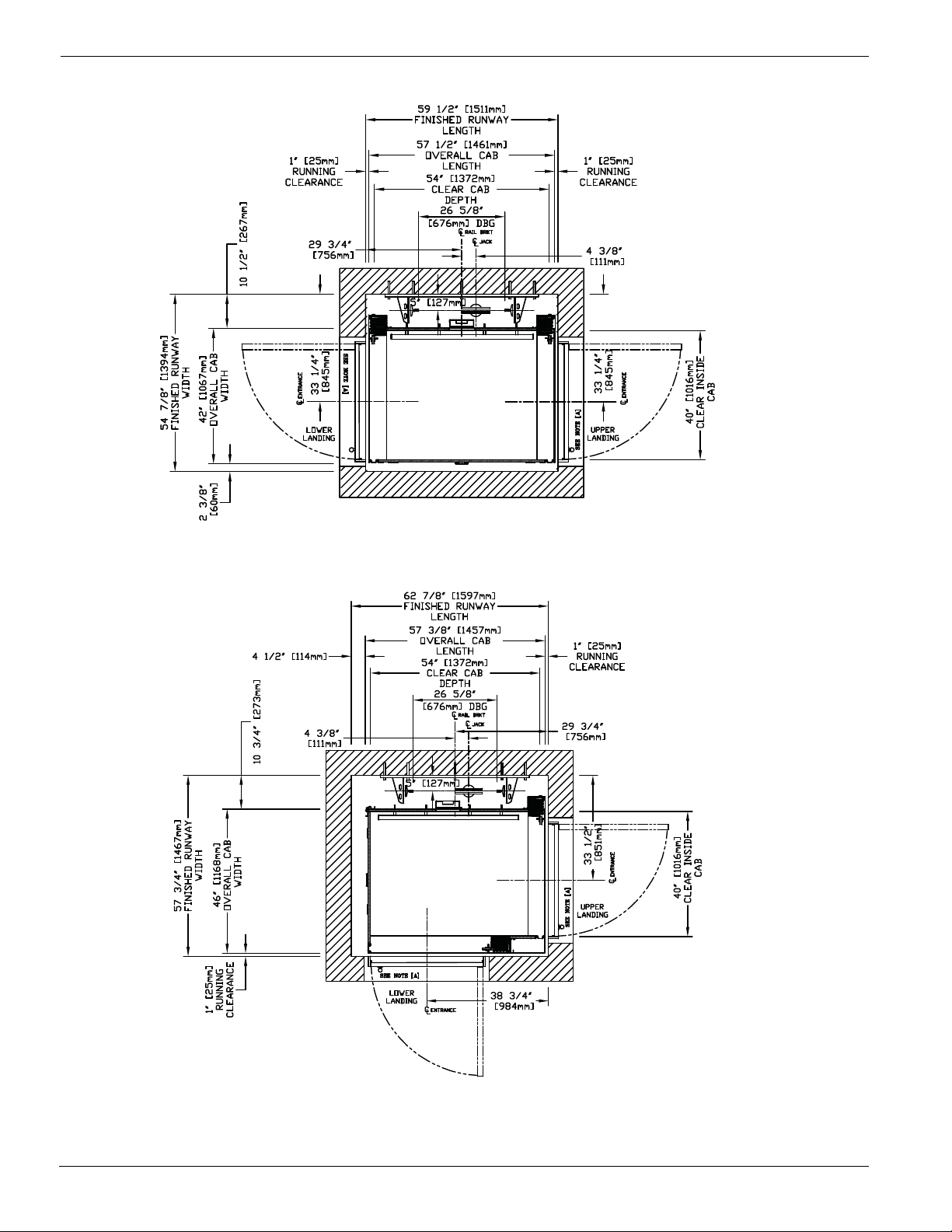
Plan view – Infinity 40” x 54” type 2 29-
Plan view – Infinity 40” x 54” type 3 30-
IMPORTANT: Always refer to your plan drawings for dimensions specific to your site.
For Infinity with Auto Slim Doors, DO NOT use the above drawings; refer to Appendix A instead.
Infinity and Infinity HD Planning Guide Part No. 000783, 24-m09-2015
Page 23
23
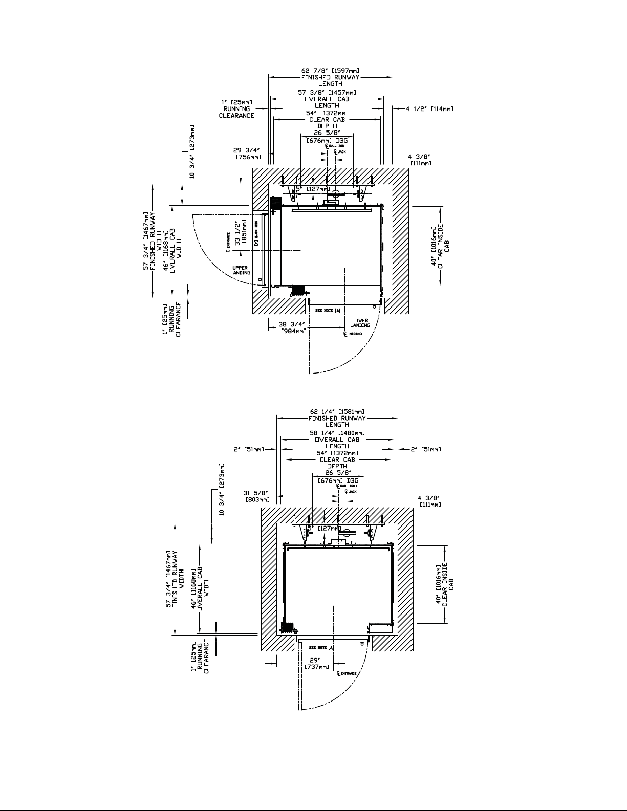
Plan view – Infinity 40” x 54” type 4 31-
Plan view – Infinity 40” x 54” type 5 32-
IMPORTANT: Always refer to your plan drawings for dimensions specific to your site.
For Infinity with Auto Slim Doors, DO NOT use the above drawings; refer to Appendix A instead.
Part No. 000783, 24-m09-2015 Infinity and Infinity HD Planning Guide
Page 24
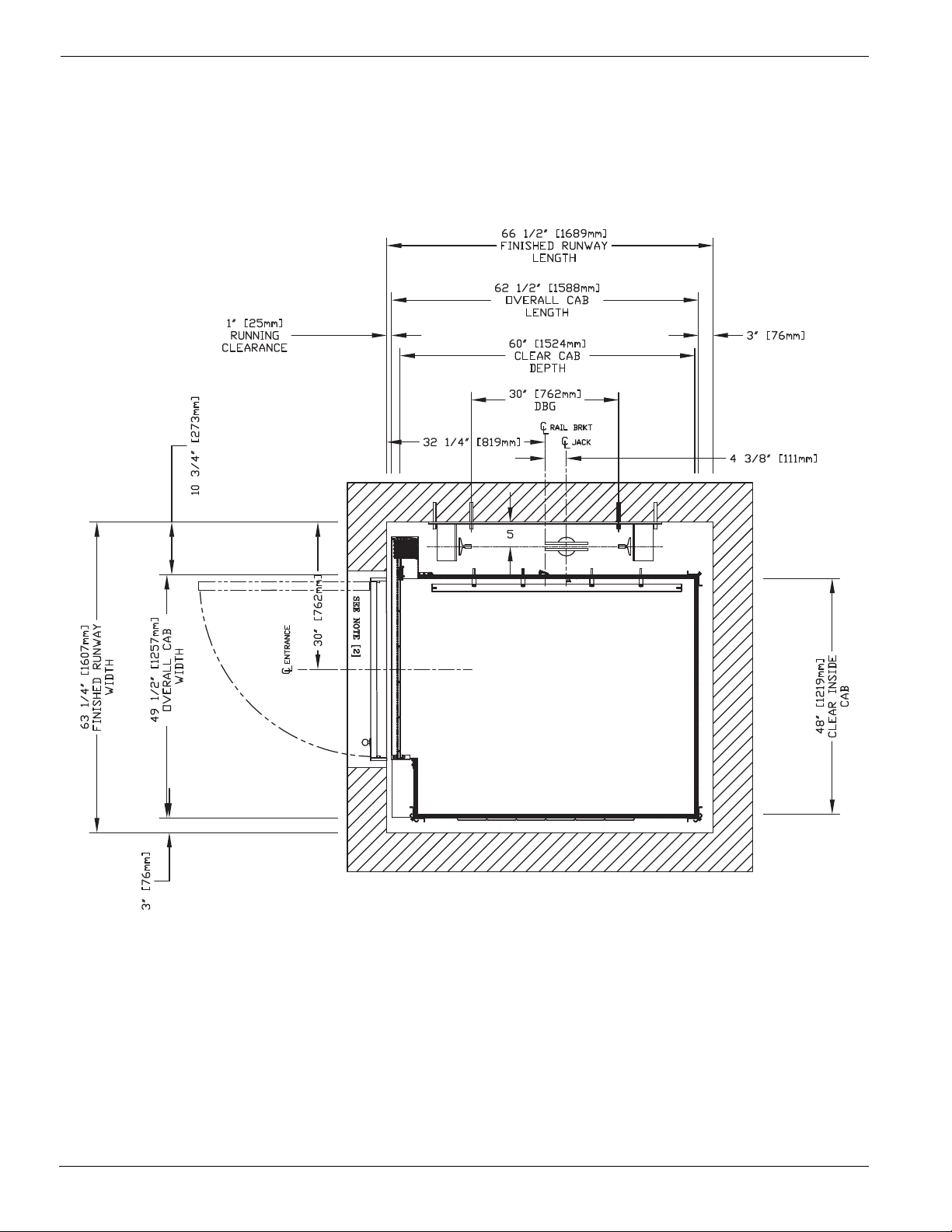
24
Plan view – Infinity HD 48” x 60” type 1 left-hand 33-
Infinity and Infinity HD Planning Guide Part No. 000783, 24-m09-2015
Page 25
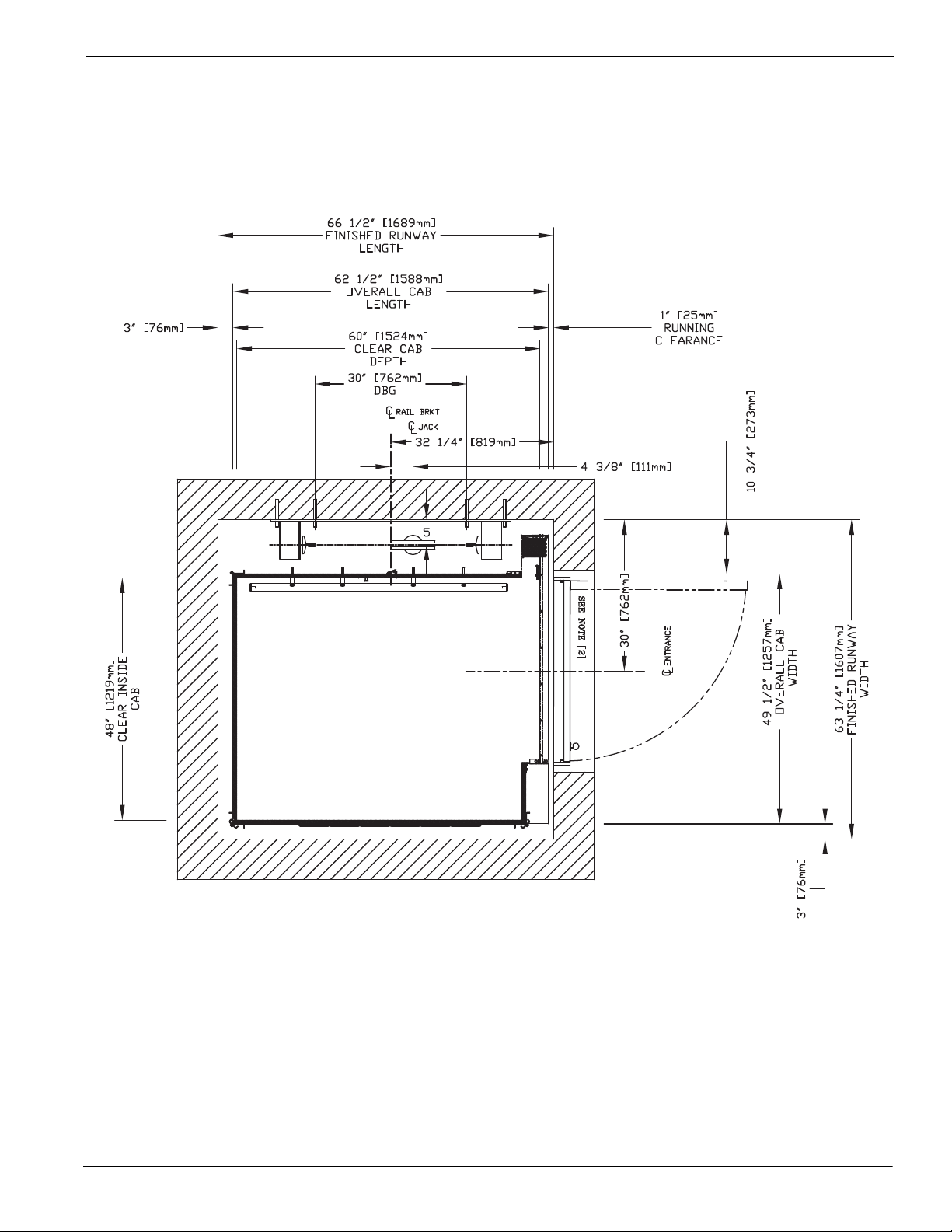
25
Plan view – Infinity HD 48” x 60” type 1 right-hand 34-
Part No. 000783, 24-m09-2015 Infinity and Infinity HD Planning Guide
Page 26
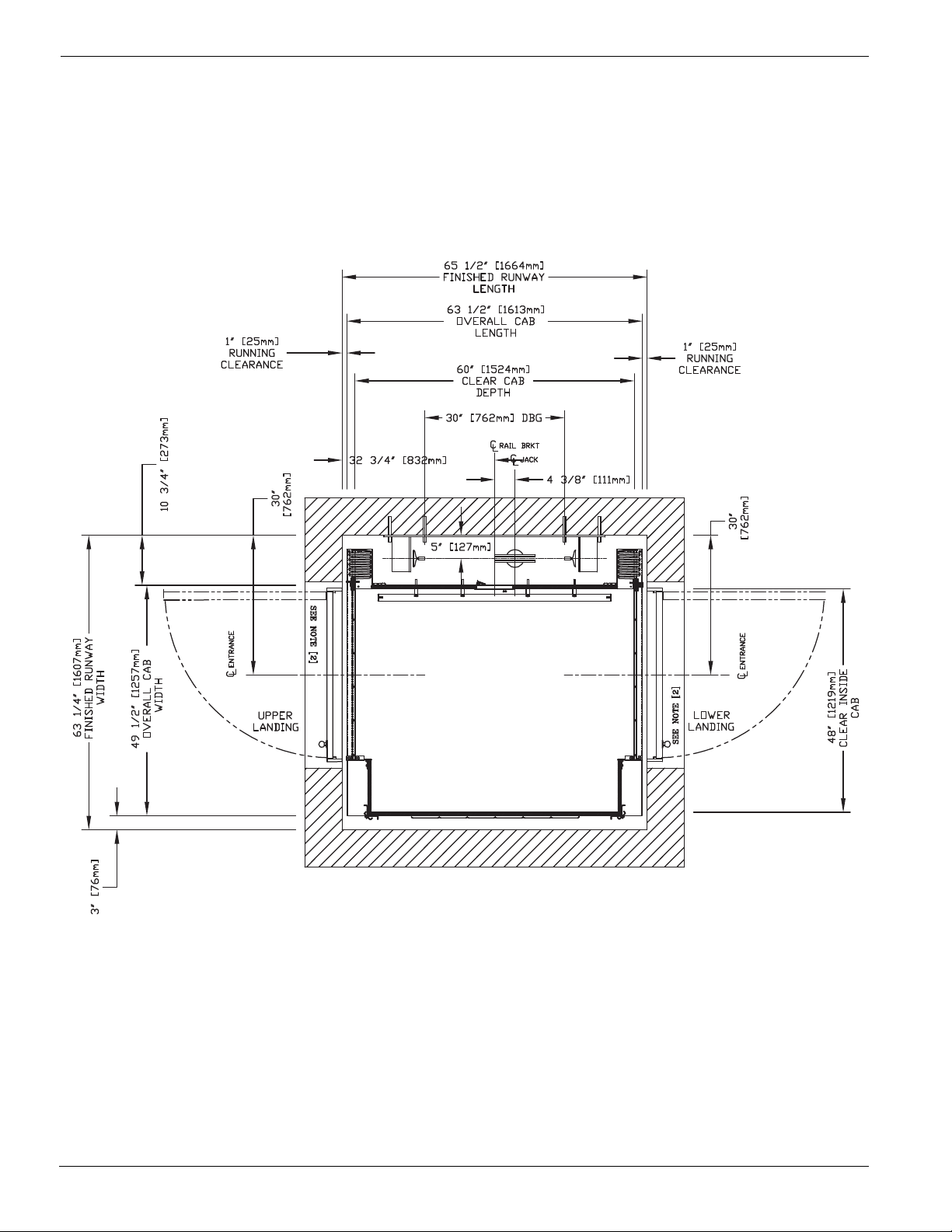
26
Plan view – Infinity HD 48” x 60” type 2 35-
Infinity and Infinity HD Planning Guide Part No. 000783, 24-m09-2015
Page 27
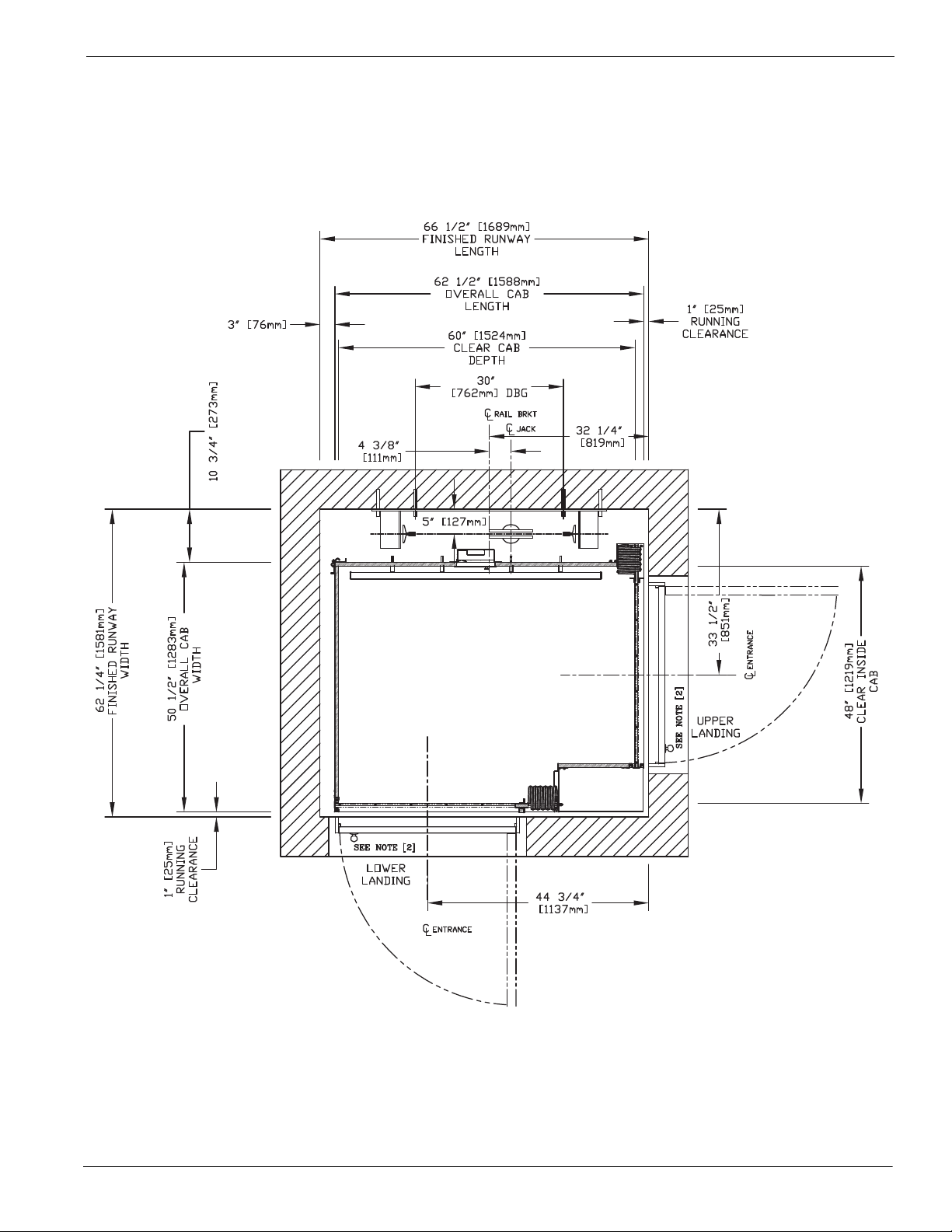
27
Plan view – Infinity HD 48” x 60” type 3 36-
Part No. 000783, 24-m09-2015 Infinity and Infinity HD Planning Guide
Page 28
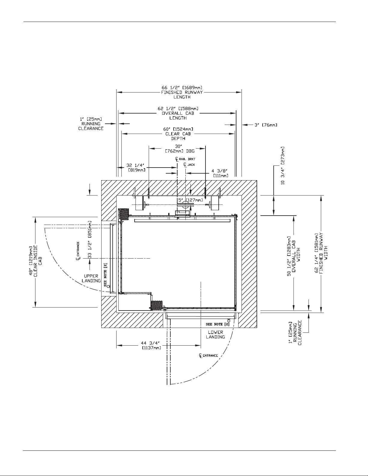
28
Plan view – Infinity HD 48” x 60” type 4 37-
Infinity and Infinity HD Planning Guide Part No. 000783, 24-m09-2015
Page 29
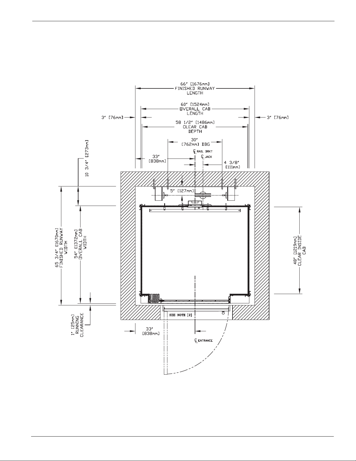
29
Plan view – Infinity HD 48” x 60” type 5 (left-hand gate stack/door swing) 38-
Part No. 000783, 24-m09-2015 Infinity and Infinity HD Planning Guide
Page 30
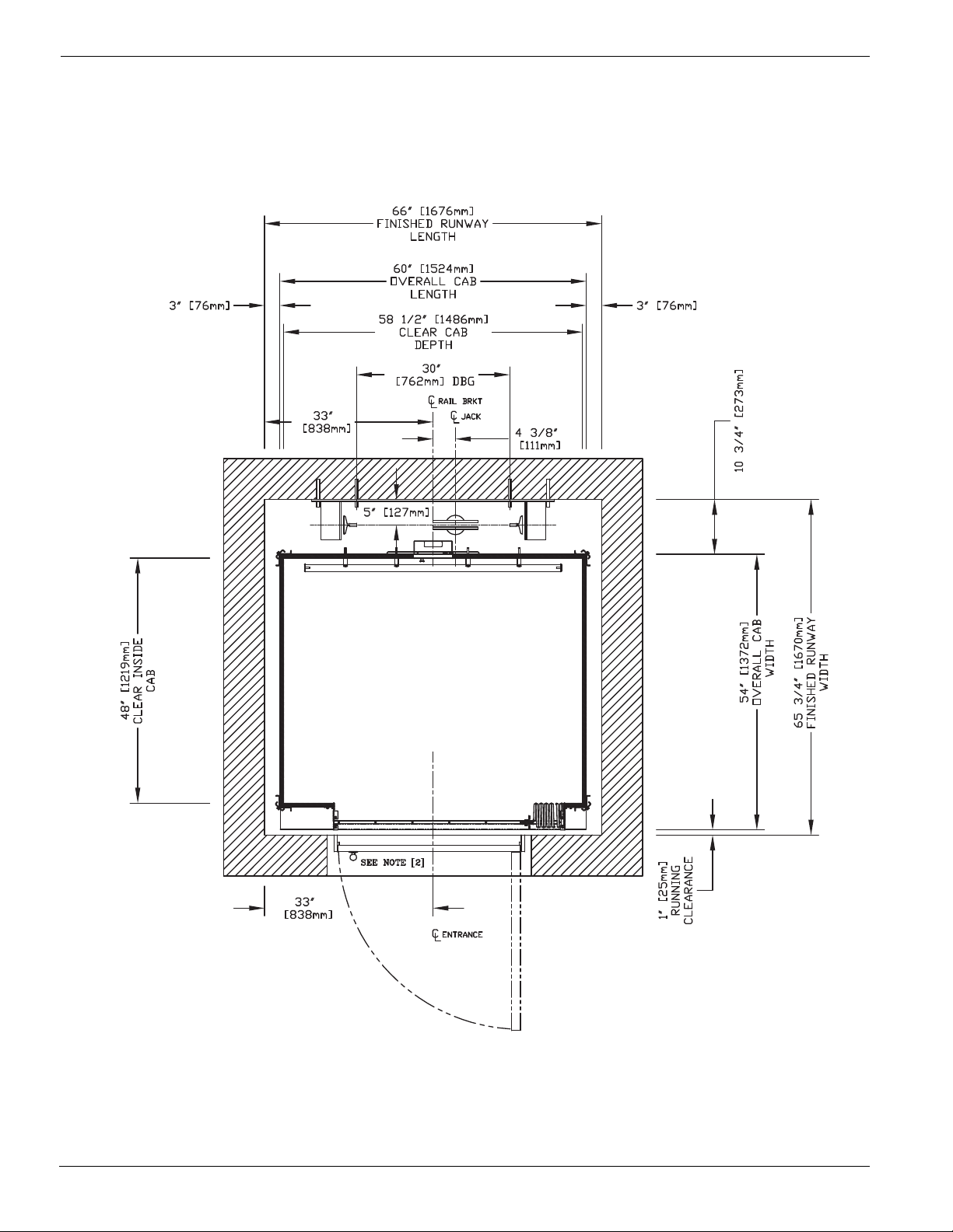
30
Plan view – Infinity HD 48” x 60” type 5 (right-hand gate stack/door swing) 39-
Infinity and Infinity HD Planning Guide Part No. 000783, 24-m09-2015
Page 31

31
Door and gate specifications 40-
For door and gate specifications, go to our website www.savaria.com, select the “architects and
builders” tab at the top of the page and then select “Doors and Gates” from the menu on the
left-hand side of the page.
The link is as follows: http://www.savaria.com/architects/drawings/doors-gates/index.php.
Recommendation: We recommend installation of a solid door as a hollow door may be too
flexible and cause potential lock issues.
Part No. 000783, 24-m09-2015 Infinity and Infinity HD Planning Guide
Page 32
32
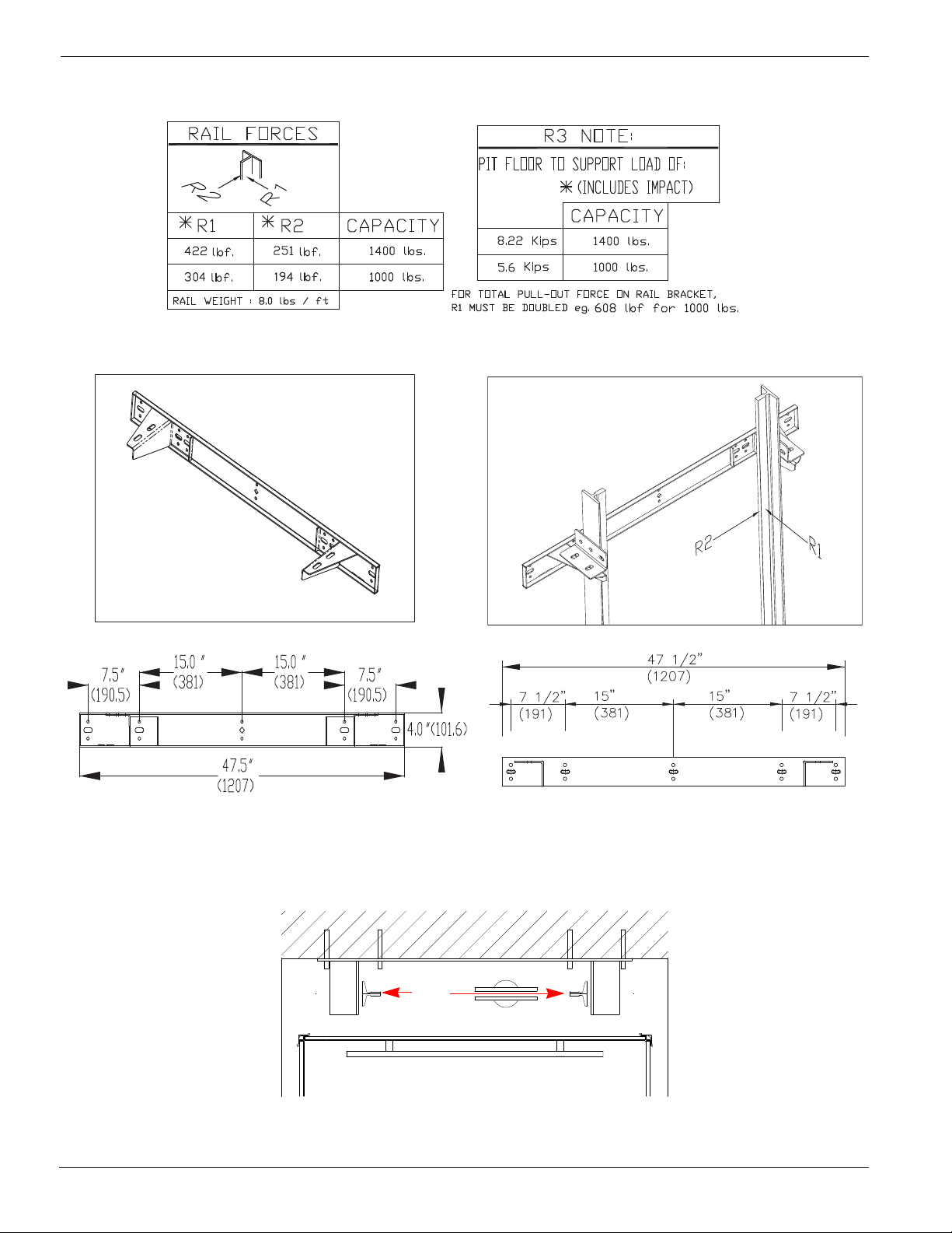
Rail bracket dimensions (Infinity)
Support wall orientation
Rails
Rail bracket dimensions (Infinity HD)
Loads on building and rail dimensions 41-
Infinity and Infinity HD Planning Guide Part No. 000783, 24-m09-2015
Page 33
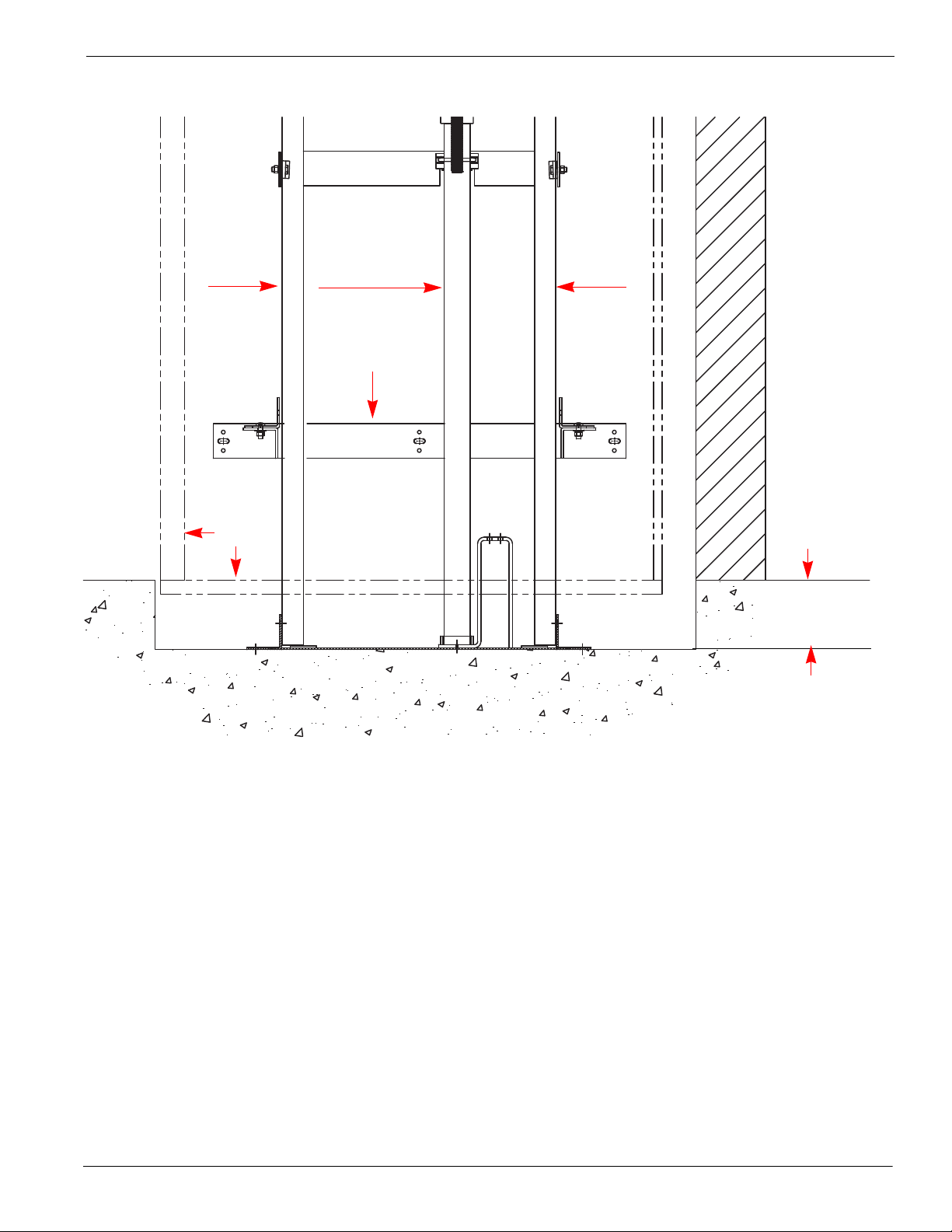
33
Cab
Pit
Guide rails
Rail bracket
Guide rails
Upstand post for
hydraulic jack
8” (203 mm) or
min. pit depth
12” (305 mm)
Pit details 42-
Hoistway and pit notes
• A load bearing wall is required to sustain rail reactions (refer to the section “Loads on building”
on the previous page).
• Suggested hoistway pit floor construction consists of an 8” (203 mm) concrete slab poured on
a natural or compacted soil with a minimum allowable bearing pressure of 1.0 KSF.
• The minimum compressive strength of the concrete at 28 days must be no less than 3000 PSI.
#5 reinforcing steel (grade 60) must be placed at the bottom of the slab in two traverse
directions and at a spacing of 12” (305 mm).
• Hoistway pit floor to support a load (including impact) of 5.6 kips (5600 lb/24.9 kN) for Infinity
or 8.22 kips (8220 lb/36.6 kN) for Infinity HD.
• Minimum overhead clearance of 92” (2337 mm) for 80” (2032 mm) cab, 96” (2438 mm) for 84”
cab, and 108” (2743 mm) for 96” cab.
• Minimum pit depth of 8” (203 mm) for Infinity and 12” (305 mm) for Infinity HD.
• Hoistway sizes reflect running and access clearances only. Consult your local AHJ to assure
compliance with local codes.
• Hoistway is required to be free of all pipes, wiring and obstructions not related to the operation
of the elevator.
Part No. 000783, 24-m09-2015 Infinity and Infinity HD Planning Guide
Page 34
34
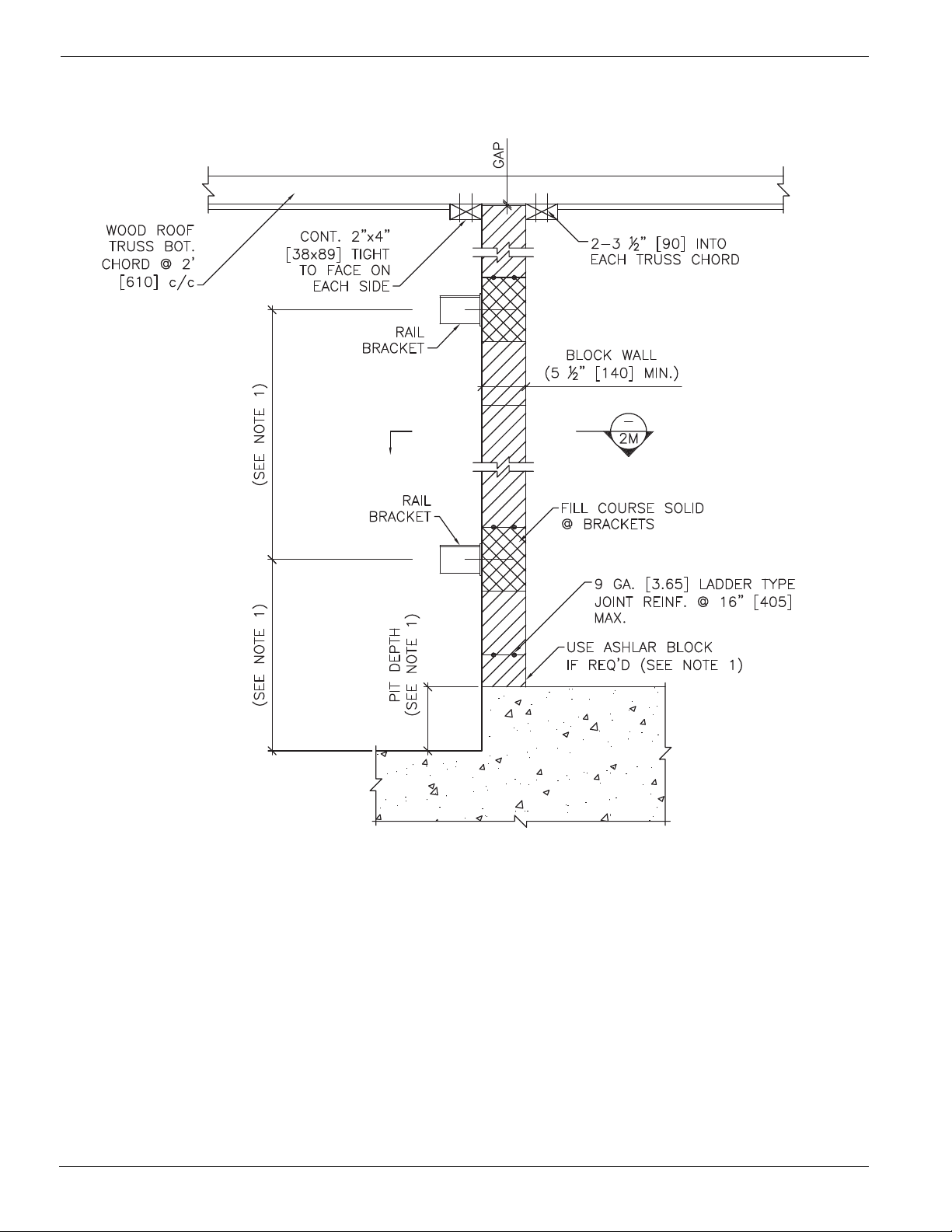
Masonry construction – sectional view 43-
Infinity and Infinity HD Planning Guide Part No. 000783, 24-m09-2015
Page 35
35
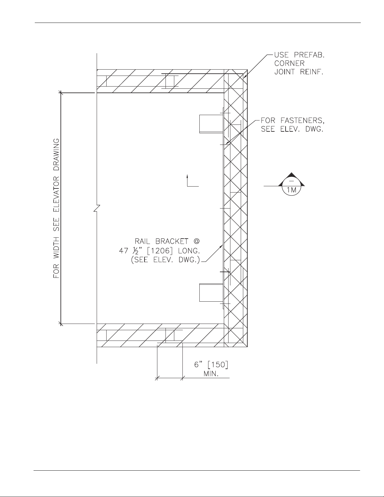
Masonry construction – plan view 44-
Part No. 000783, 24-m09-2015 Infinity and Infinity HD Planning Guide
Page 36
36
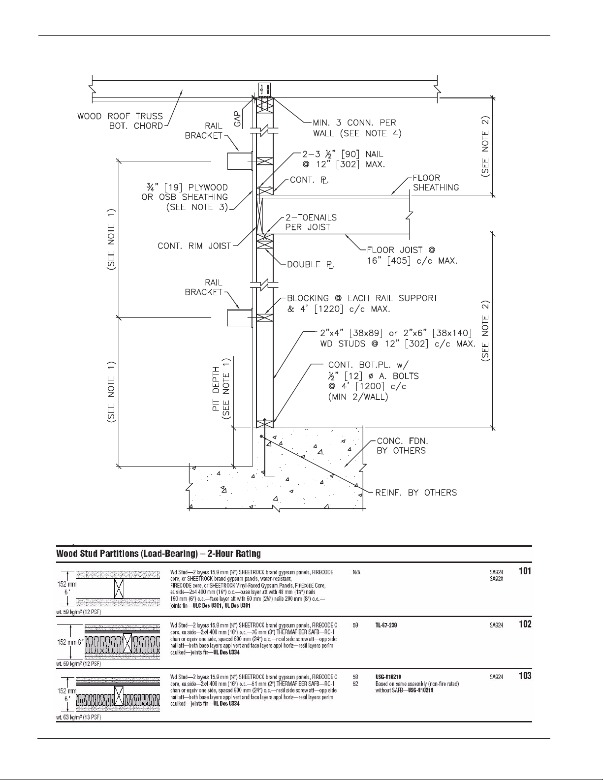
For Reference Only
Wood construction – sectional view 45-
Infinity and Infinity HD Planning Guide Part No. 000783, 24-m09-2015
Page 37

37
Wood construction – plan view 46-
Part No. 000783, 24-m09-2015 Infinity and Infinity HD Planning Guide
Page 38
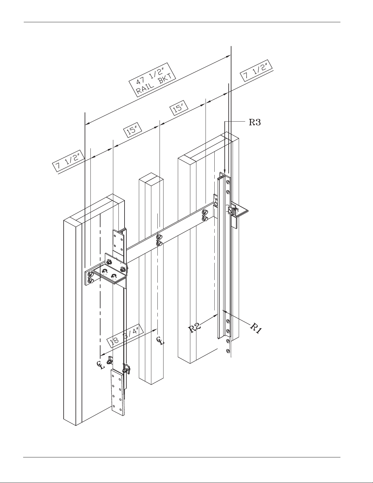
38
Refer to previous section
“Loads on building” for
rail forces R1, R2, R3.
Suggested wall configuration for wood construction (sheet 1) 47-
Infinity and Infinity HD Planning Guide Part No. 000783, 24-m09-2015
Page 39
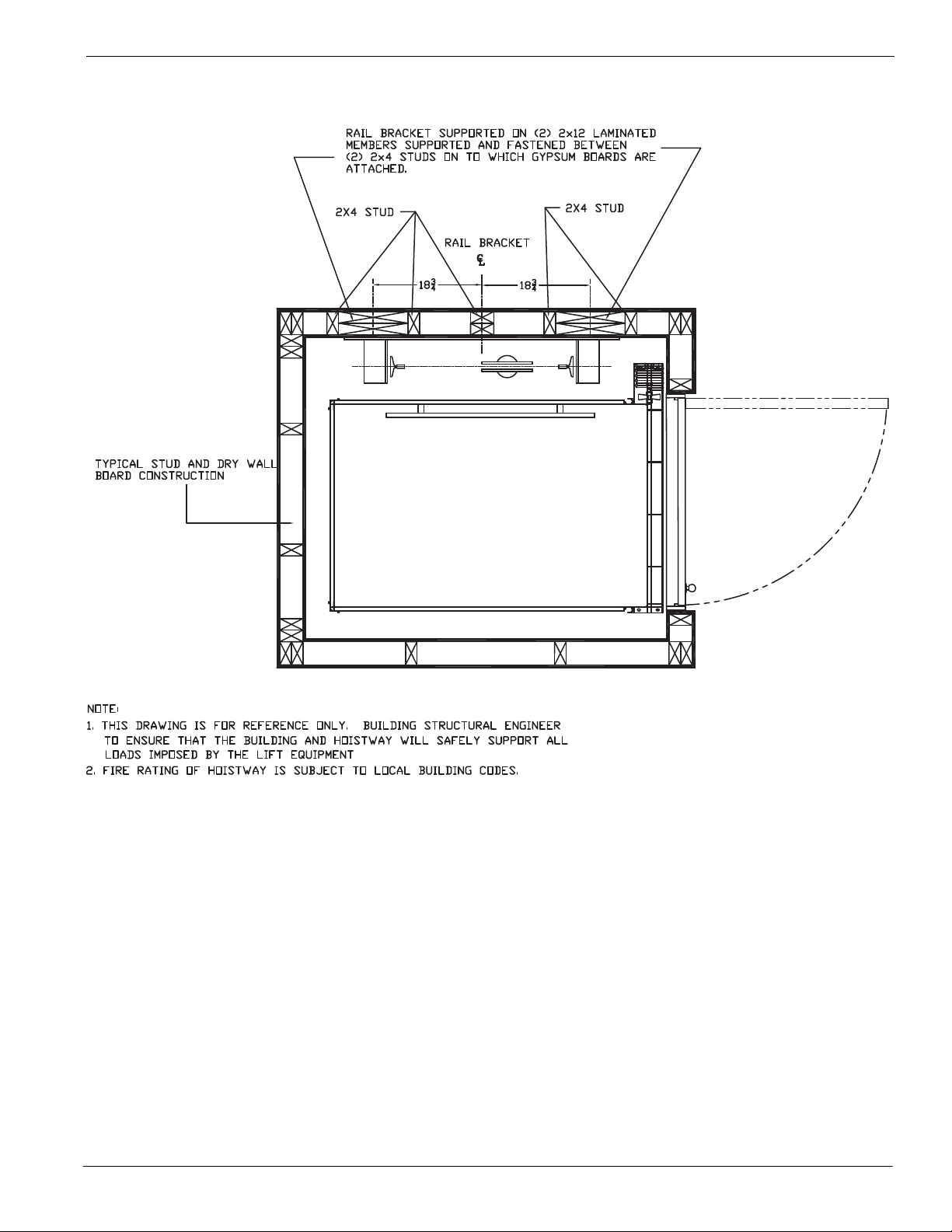
39
Suggested wall configuration for wood construction (sheet 2) 48-
Part No. 000783, 24-m09-2015 Infinity and Infinity HD Planning Guide
Page 40

40
Rail support wall specifications 49-
Drawing notes
1) See the lift installation (shop) drawings for rail bracket spacing and pit depth.
2) Wall lateral support spacing:
• For 2” x 4” studs, use 6 ft 10” (2090 mm) max.
• For 2” x 6” studs, use 13 ft 6” (4120 mm) max.
3) Sheathing installation: install sheets vertically full width of shaft or min. centred on rail brackets.
4) Connectors to resist horizontal load but allow vertical movement. For wood, use 2” x ¼” cap screw lag bolts.
General specifications
G1 The design and construction of all work is to conform to the local applicable building code.
G2 Read the installation (shop) drawings in conjunction with all related architectural, mechanical, electrical, and
lift drawings as well as any other contract documents.
G3 The wall drawings have been prepared using engineering principles and the design loads that are applied by
the lift rails to the wall. However, the details and member sizes and the attachments to the structure should
not be construed as a complete design of the wall system. The contractor and/or the project engineer is
responsible to evaluate the other loads that are applied to the wall from the floor or roof system and modify
member sizes or connections as required by their analysis.
G4 Do not scale the drawings.
G5 See the lift installation (shop) drawings for service loads (including dynamic effects) which are:
• Horizontal load parallel to the wall: 194 lbf (0.86 kN) for Infinity; 251 lbf (1.12 kN) for Infinity HD
• Horizontal load perpendicular to the wall: 304 lbf (1.35 kN) for Infinity; 422 lbf (1.88 kN) for Infinity HD
G6 Wood: SPF NO 1/2 Mix
Concrete: 3000 psi (20 Mpa) @ 28 days. If exposed use 5% to 7% air content.
Anchor bolts: ASTM A307
Mortar: Type “S”
Masonry grout: 2100 psi (14 Mpa) high slump
Masonry block: 2100 psi (14 Mpa) on net area
G7 Wall to be installed plumb and square within 1/8” (3 mm) of top and bottom of shaft.
G8 Wall lateral support spacing (H) selected for maximum horizontal deflection of H/360 from rail loads.
Wood construction
W1 Separate wood from concrete with waterproof barrier or use pressure treated wood.
W2 Bridging maximum spacing: Load bearing or shear walls – 4 ft (1219 mm) c/c.
W3 Nail or screw sheathing at 6” (152 mm) c/c at edges and 12” c/c to other members.
Use 2.5” standard Ardox nails or 2” #12 screws.
Masonry construction
M1 All masonry construction to conform to applicable local standards
M2 Reinforce lintel blocks with 2 m-15 m bottom bars unless noted.
M3 Provide continuous ladder type joint reinforcement at 16” (400 mm) c/c.
Infinity and Infinity HD Planning Guide Part No. 000783, 24-m09-2015
Page 41

41
Provisions by others 50-
Hoistway
o The hoistway must be designed and built in accordance with all applicable codes (identified on the cover of
this manual) and all state and local codes.
o Due to close running clearances, owner/agent must ensure that hoistway and pit (where provided) are level,
plumb and square and are in accordance with the dimensions on the installation (shop) drawings.
Minimum overhead clearance
o Owner/agent must ensure minimum overhead clearance is in compliance with codes.
Construction site
o Owner/agent to provide all masonry, carpentry and drywall work as required and shall patch and make good
(including finish painting) all areas where walls/floors may need to be cut, drilled or altered in any way to
permit the proper installation of the lift.
Dimensions
o Contractor/customer to verify all dimensions and report any discrepancies to our office immediately.
Structural
o Structural engineer to assure that building and shaft will safely support all loads imposed by the lift
equipment. Refer to the tables on installation (shop) drawings for loads imposed by the equipment.
o Suitable lintels must be provided by owner/agent. Door frames are not designed to support overload wall
loads.
Entrances
o Entrance assemblies must be adjusted to align with platform and interlock equipment. Others to allow an
adequate rough opening.
o Return walls at entrances must be built-in by others after entrance assemblies are in place. Entrance assembly
must be securely fastened to walls by elevator contractor.
o Fascia panel below upper level entrance where required. Fascia panel must be fastened to a solid wall and be
perpendicular to the floor and walls. Hoistway fascia is not self-supporting for long, continuous runs void of
entrances. Adequate support for the fascia must be provided.
Machine room
o Machine room must be located at the lowest level adjacent to hoistway, unless shown otherwise on
installation (shop) drawings. Field adjustment by installer may be necessary to meet job site conditions or
regulations. Access to machine room to be through self-closing lockable door.
o Sleeves for oil and electric lines must be provided from machine room to runway as required (positioned per
installer’s instructions).
Electrical
o Power supply with a lockable fused disconnect and auxiliary contact to break the battery feed, or circuit
breakers with a 3-pole breaker for battery feed required, in compliance with electrical code, located on the
wall on the lock jamb side of the machine room door. Contact your Savaria dealer or refer to one of the tables
on the next page for OEM part numbers.
o Permanent power of 208 volts, three-phase, 30 amps or 230 volts, single-phase, 40 amps must be supplied by
others before installation begins.
o Owner/agent to ensure at least 9.3 foot-candles (100 lux) ambient lighting over lift area.
o Remote hall call (when supplied) to be installed by the owner/agent at 42” (1067 mm) from landing floor and
8” (203 mm) from the door edge.
Part No. 000783, 24-m09-2015 Infinity and Infinity HD Planning Guide
Page 42
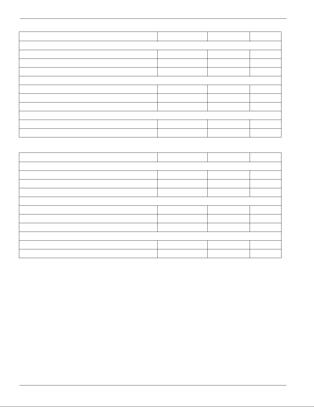
42
For Infinity (3 HP pump unit)
Disconnect Switch Types & Accessories Cutler Hammer Federal Pioneer Siemens
1 Phase 3 H.P. Pump Unit
2 Pole 240V 1 PH 1HD221N 1322SN ID321
Required Auxiliary Contact DS16CP E1K-1AEV-W94 MSSAK 116
Required Type “D” Fuse (Buss type “FRN” or equal) 2@30 amp 2@30 amp 2@30 amp
3 Phase 3 H.P. Pump Unit
3 Pole 208V 3 PH 1HD321N 1332SN ID321
Required Auxiliary Contact DS16CP E1K-1AEV-W94 MSSAK 116
Required Type “D” Fuse (Buss type “FRN” or equal) 3@20 amp 3@20 amp 3@20 amp
Cab Lighting
1 Pole Solid Neutral 120V 1 PH GP 111N 86211 CFN 211
Required Type “D” Fuse (Buss type “T” or equal) 1@15 amp 1@15 amp 1@15 amp
For Infinity HD (5 HP pump unit)
Disconnect Switch Types & Accessories Cutler Hammer Federal Pioneer Siemens
1 Phase 5 H.P. Pump Unit
2 Pole 240V 1 PH 1HD221N 1322SN ID321
Required Auxiliary Contact DS16CP E1K-1AEV-W94 MSSAK 116
Required Type “D” Fuse (Buss type “FRN” or equal) 2@40 amp 2@40 amp 2@40 amp
3 Phase 5 H.P. Pump Unit
3 Pole 208V 3 PH 1HD321N 1332SN ID321
Required Auxiliary Contact DS16CP E1K-1AEV-W94 MSSAK 116
Required Type “D” Fuse (Buss type “FRN” or equal) 3@30 amp 3@30 amp 3@30 amp
Cab Lighting
1 Pole Solid Neutral 120V 1 PH GP 111N 86211 CFN 211
Required Type “D” Fuse (Buss type “T” or equal) 1@15 amp 1@15 amp 1@15 amp
Infinity and Infinity HD Planning Guide Part No. 000783, 24-m09-2015
Page 43
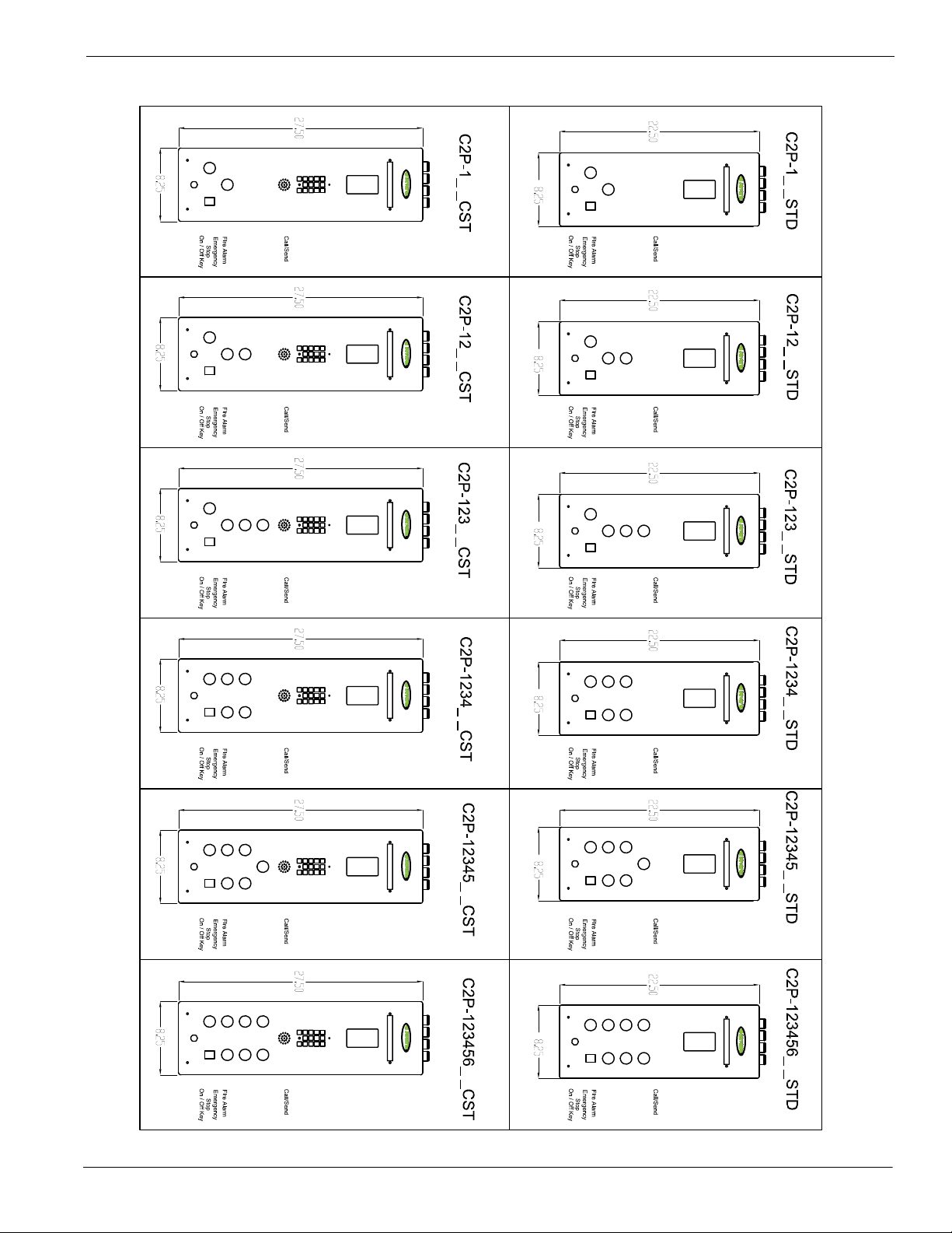
43
COP dimensions 51-
Part No. 000783, 24-m09-2015 Infinity and Infinity HD Planning Guide
Page 44
44
Hall call dimensions 52-
Infinity and Infinity HD Planning Guide Part No. 000783, 24-m09-2015
Page 45

Appendix A
Infinity with Auto Slim Doors
This appendix provides elevation and plan view drawings for the various Infinity cab types with
Auto Slim Doors.
Drawings for the auto slim doors entrance assembly are provided on the next two pages.
45
Part No. 000783, 24-m09-2015 Infinity and Infinity HD Planning Guide
Page 46

46
Auto slim doors entrance assembly, CO = 2100
Infinity and Infinity HD Planning Guide Part No. 000783, 24-m09-2015
Page 47
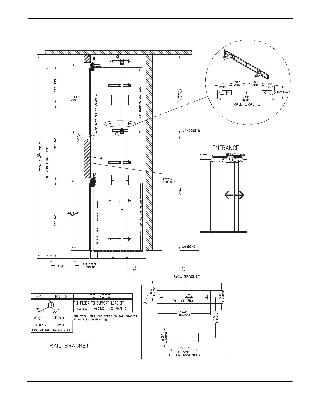
Elevation view – Infinity type 1L with auto slim doors
47
Part No. 000783, 24-m09-2015 Infinity and Infinity HD Planning Guide
Page 48
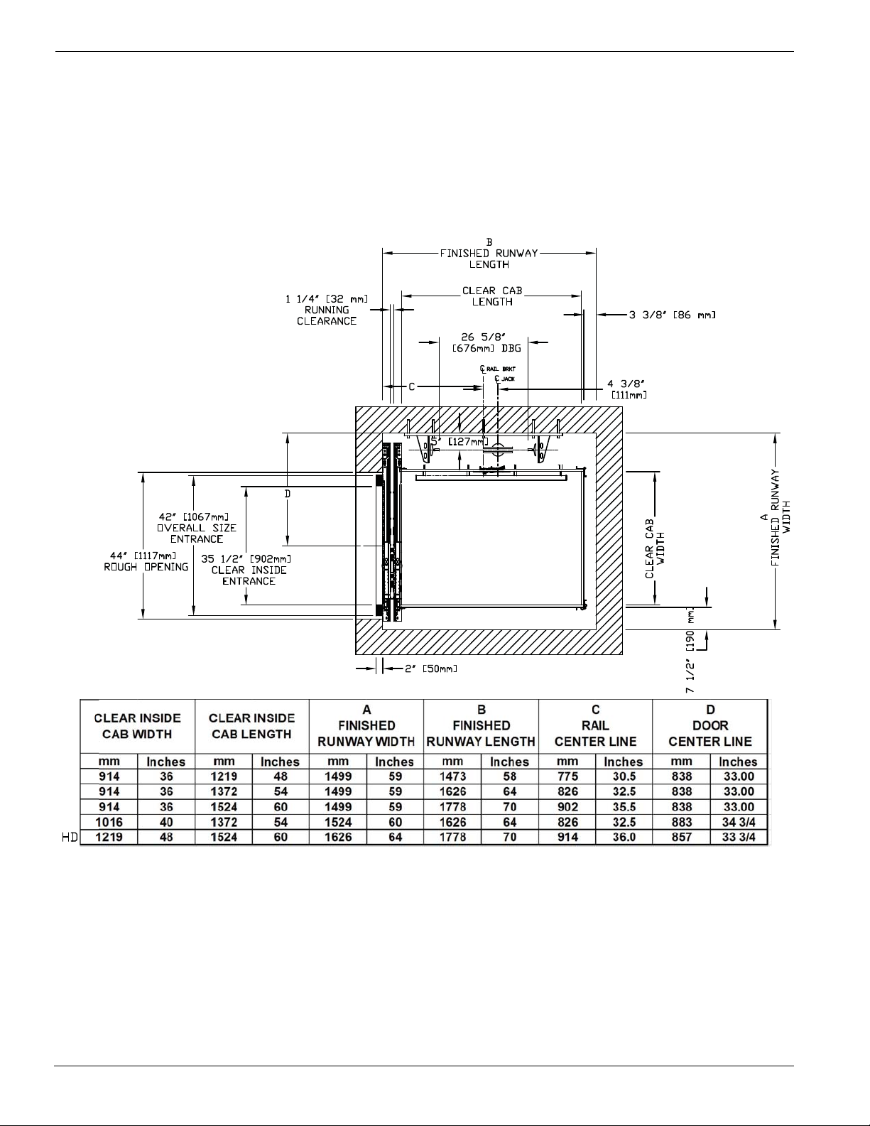
48
Plan view – Infinity type 1L with auto slim doors
Infinity and Infinity HD Planning Guide Part No. 000783, 24-m09-2015
Page 49

Elevation view – Infinity type 1R with auto slim doors
49
Part No. 000783, 24-m09-2015 Infinity and Infinity HD Planning Guide
Page 50
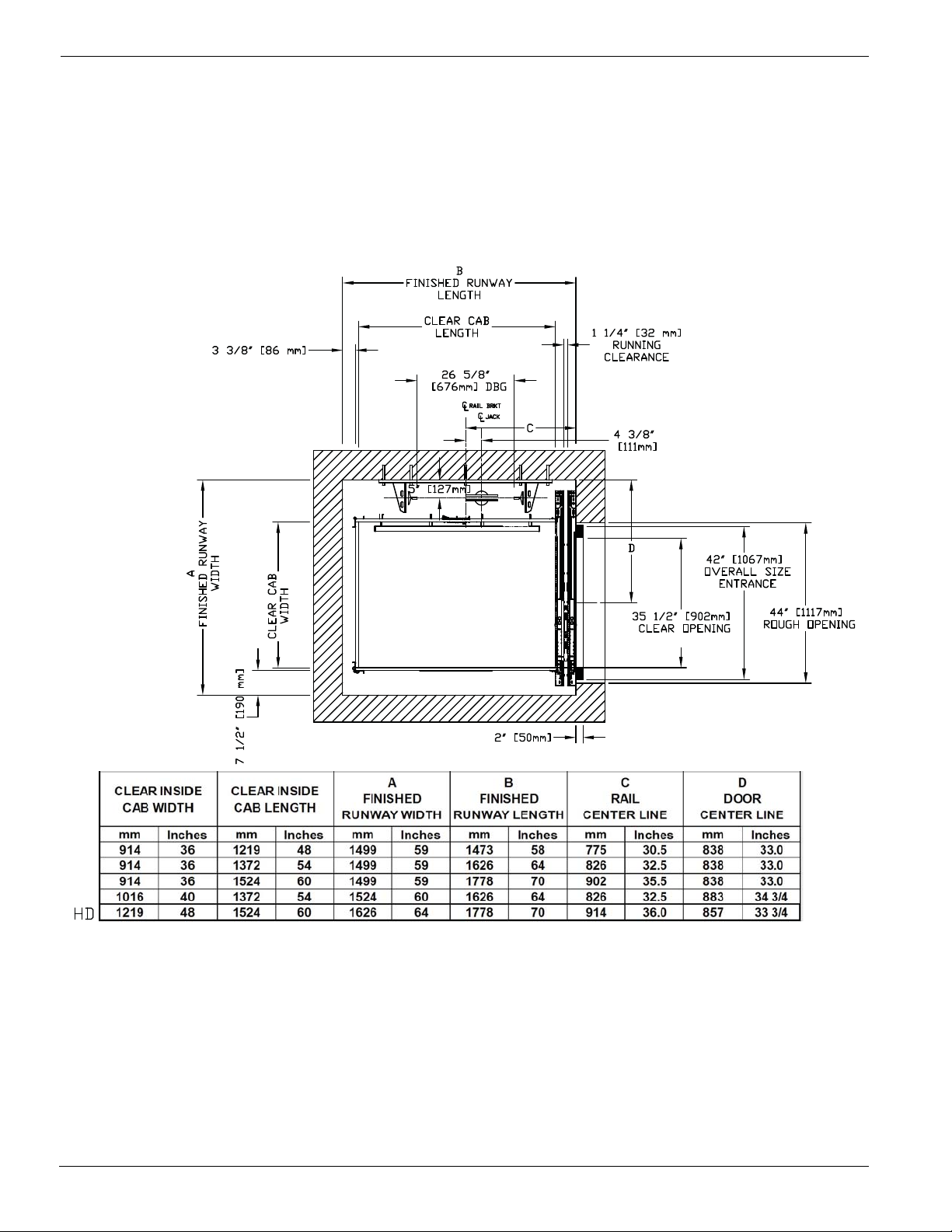
50
Plan view – Infinity type 1R with auto slim doors
Infinity and Infinity HD Planning Guide Part No. 000783, 24-m09-2015
Page 51
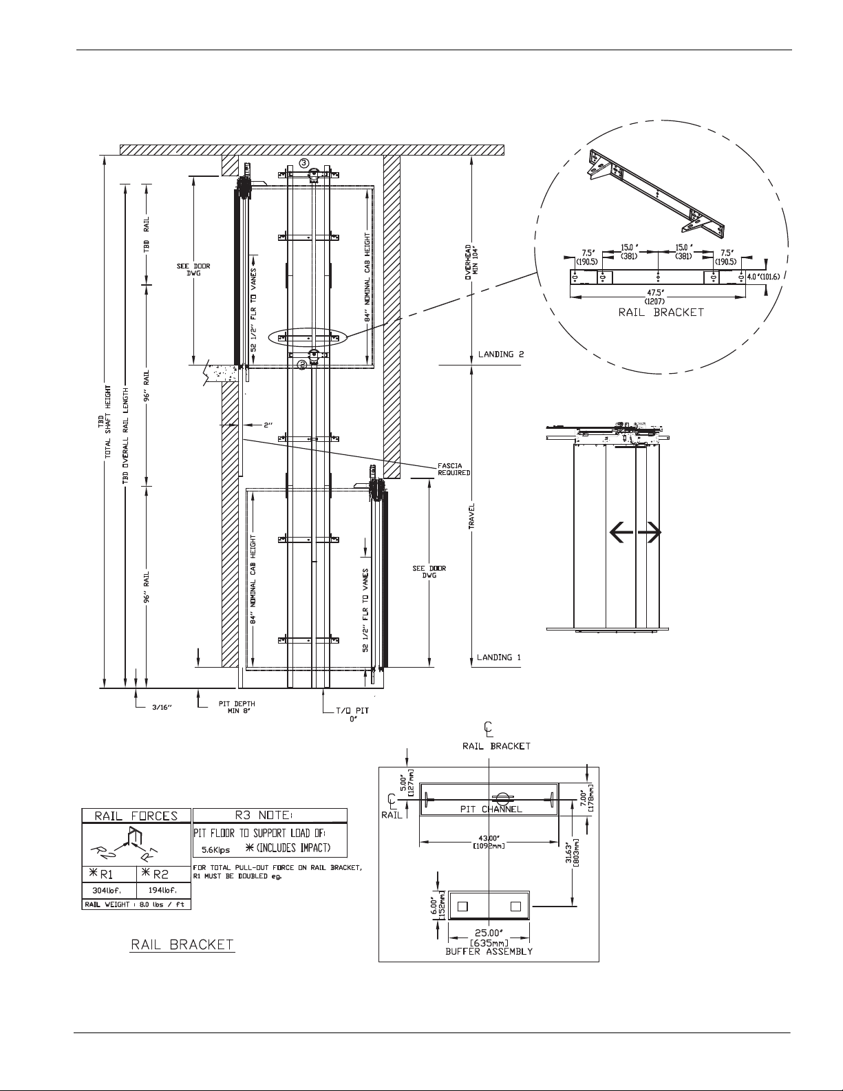
Elevation view – Infinity type 2 with auto slim doors
51
Part No. 000783, 24-m09-2015 Infinity and Infinity HD Planning Guide
Page 52
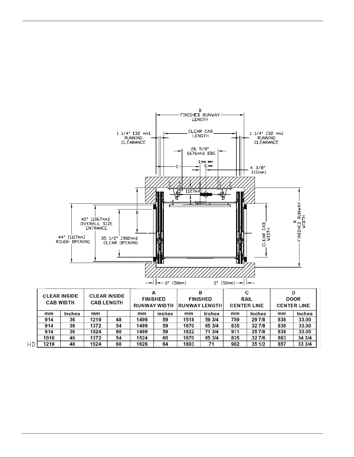
52
Plan view – Infinity type 2 with auto slim doors
Infinity and Infinity HD Planning Guide Part No. 000783, 24-m09-2015
Page 53
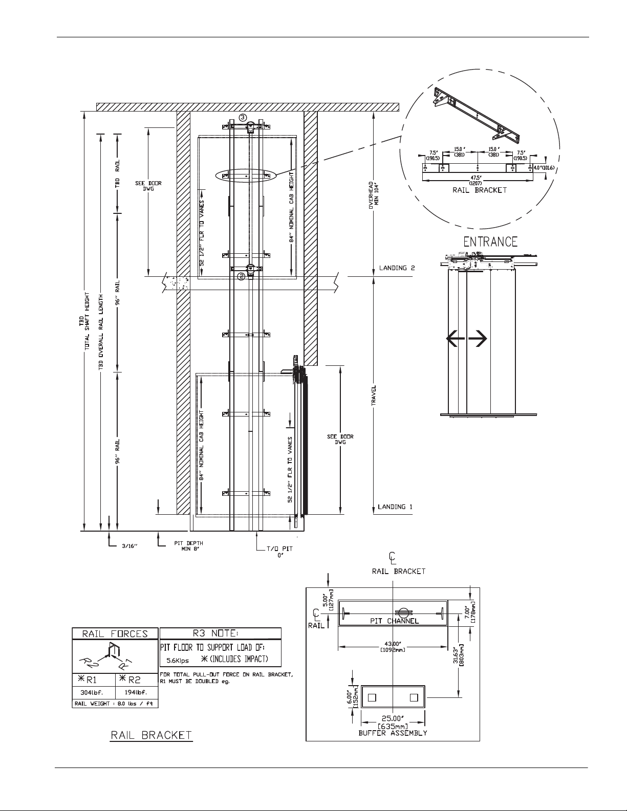
Elevation view – Infinity type 3 with auto slim doors
53
Part No. 000783, 24-m09-2015 Infinity and Infinity HD Planning Guide
Page 54
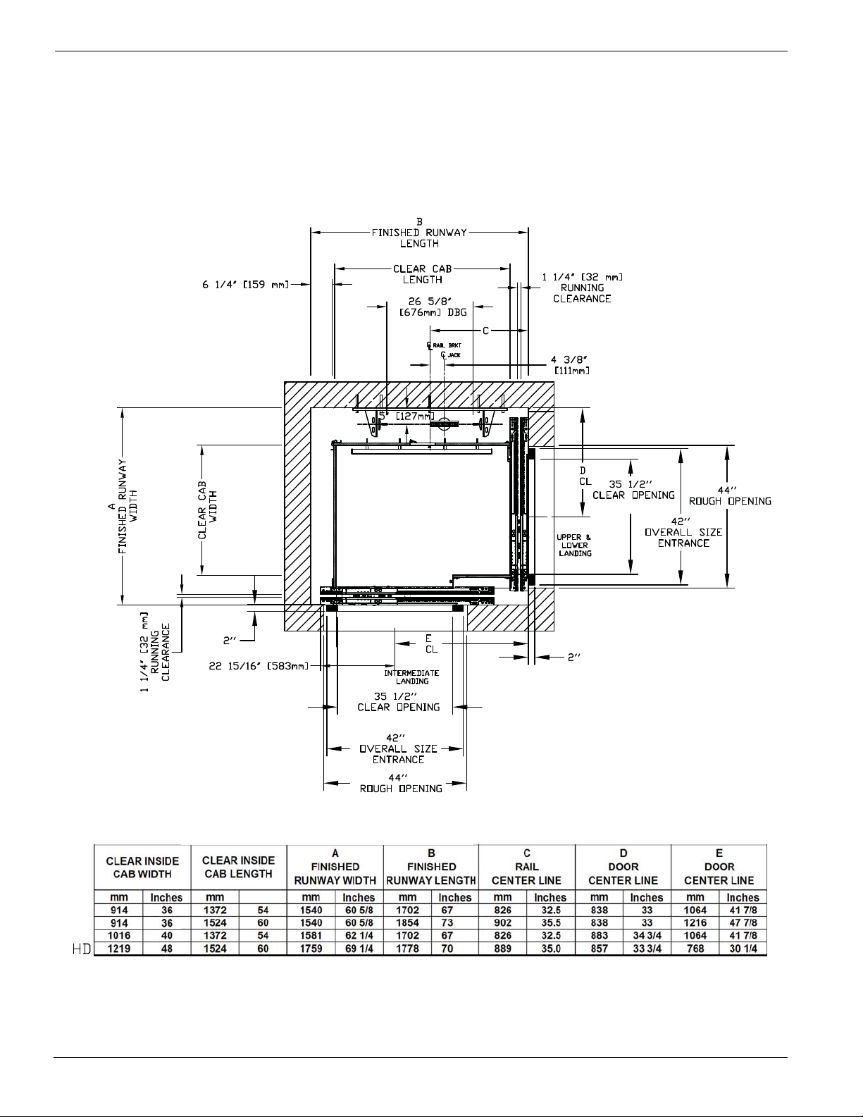
54
Plan view – Infinity type 3 with auto slim doors
Infinity and Infinity HD Planning Guide Part No. 000783, 24-m09-2015
Page 55
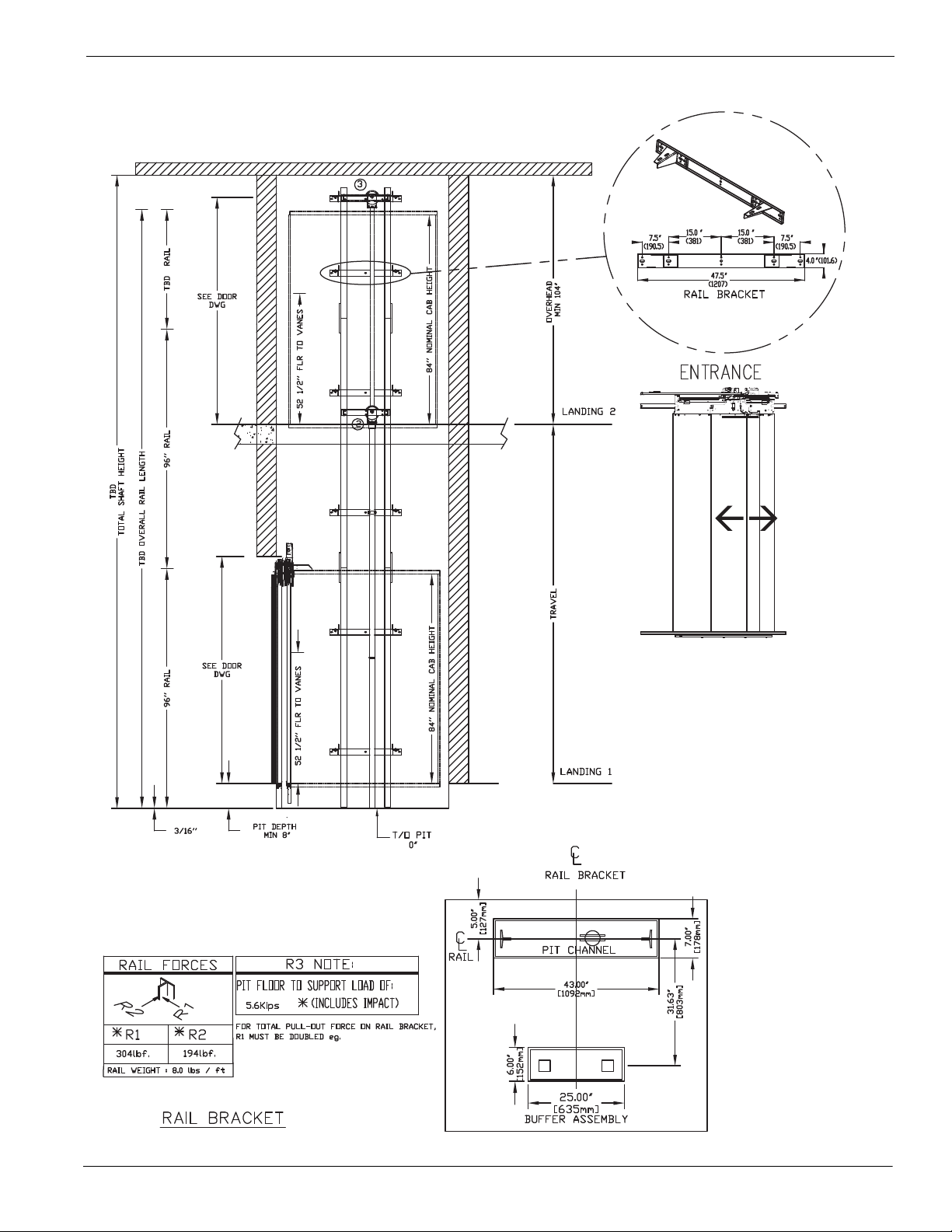
Elevation view – Infinity type 4 with auto slim doors
55
Part No. 000783, 24-m09-2015 Infinity and Infinity HD Planning Guide
Page 56
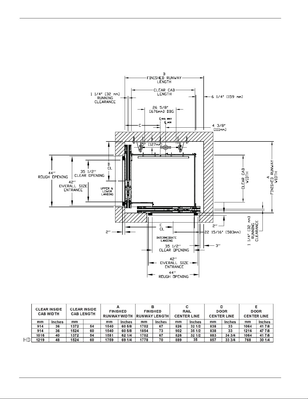
56
Plan view – Infinity type 4 with auto slim doors
Infinity and Infinity HD Planning Guide Part No. 000783, 24-m09-2015
Page 57
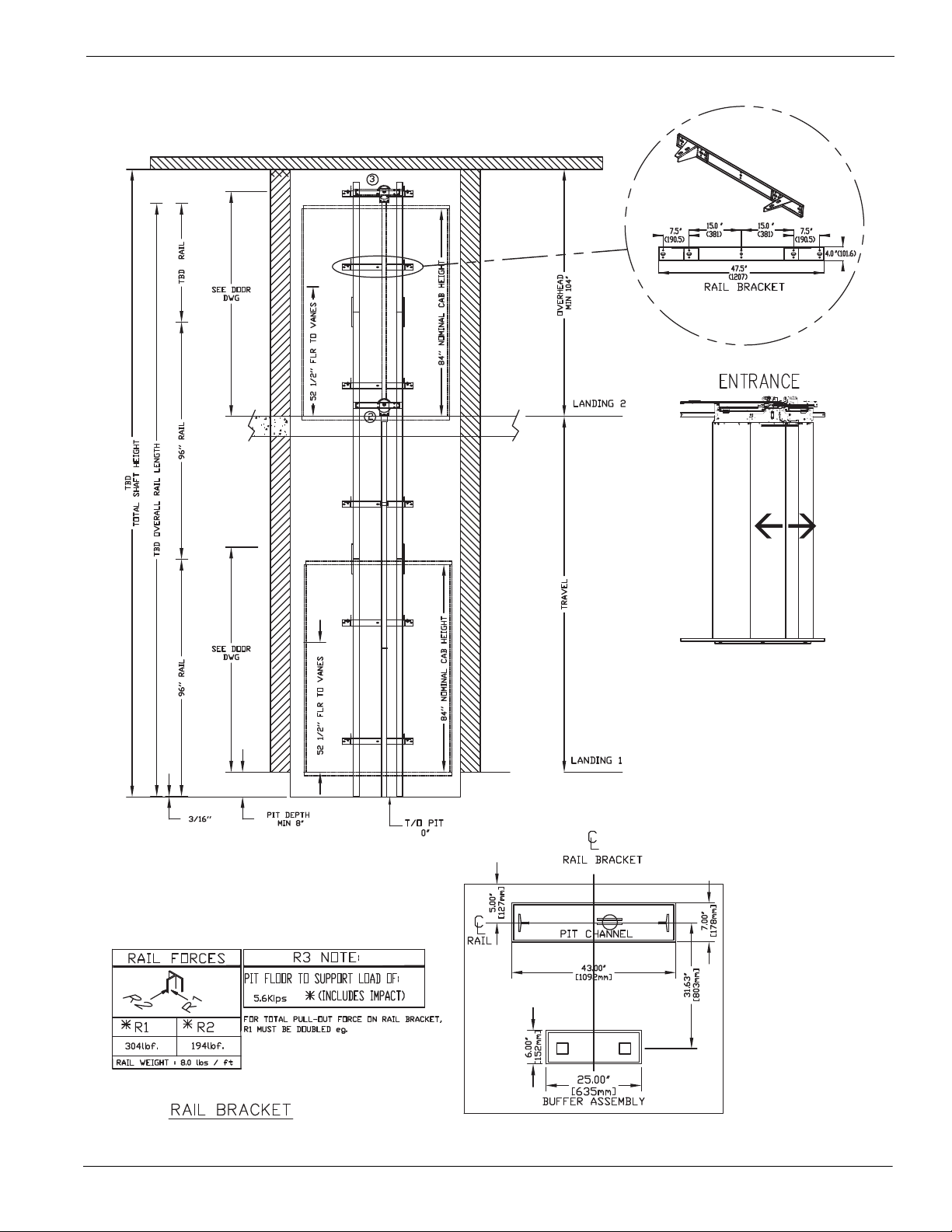
Elevation view – Infinity type 5 with auto slim doors
57
Part No. 000783, 24-m09-2015 Infinity and Infinity HD Planning Guide
Page 58
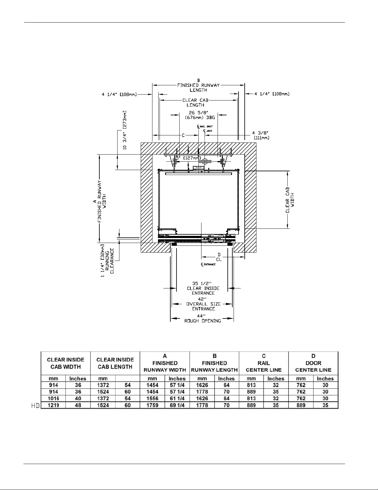
58
Plan view – Infinity type 5 with auto slim doors
Infinity and Infinity HD Planning Guide Part No. 000783, 24-m09-2015
Page 59

Page 60

2 Walker Drive
Brampton, ON Canada L6T 5E1
Phone: 905-791-5555
Fax: 905-791-2222
Sales: 800-661-5112
www.savaria.com
 Loading...