

Page 1
Operating Instructions
for
Disk-type tool turret
0.5.473.520 107 468
110 660
111 092
111 432
112 862
115 702
BA 892 e
2007-03-27
125 365
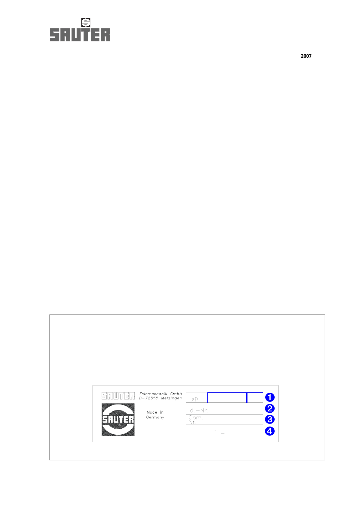
Product data as per nameplate on the housing
1. Classification number (series, size)
2. Identification number
3. Order number
4. Gear ratio
F:\Sauter\FRAME-AR\TD\0-5-473-\eng\Ba892\DB_Rev_BA-892.fm
x.x.xxx.x xx
xxx xxx
xx-xxx-xx-xx
xxx
Basis-BA: 06-10-23 Manual translation
Page 2

The present manual is part of the product.
°
The manual should be kept in an easily accessible place during the product’s lifetime.
°
The manual should be passed on to the next owner/user of the product.
°
Make sure that any possible supplement received is duly added to the manual.
Page 3

Table of contents
Interpretation of symbols . . . . . . . . . . . . . . . . . . . . . . . . . . . . . . . . 5
1 Safety notes . . . . . . . . . . . . . . . . . . . . . . . . . . . . . . . . . . . . . . . . . . . 7
1.1 Use within specifications. . . . . . . . . . . . . . . . . . . . . . . . . . . . . . . . . . 7
1.2 Required skills. . . . . . . . . . . . . . . . . . . . . . . . . . . . . . . . . . . . . . . . . . 7
1.3 Notes on product-specific risks . . . . . . . . . . . . . . . . . . . . . . . . . . . . . 7
1.4 Disposal. . . . . . . . . . . . . . . . . . . . . . . . . . . . . . . . . . . . . . . . . . . . . . . 8
1.5 Liability and warranty. . . . . . . . . . . . . . . . . . . . . . . . . . . . . . . . . . . . . 9
2 Product description. . . . . . . . . . . . . . . . . . . . . . . . . . . . . . . . . . . . 10
2.1 Designation of parts . . . . . . . . . . . . . . . . . . . . . . . . . . . . . . . . . . . . 10
2.2 Technical data. . . . . . . . . . . . . . . . . . . . . . . . . . . . . . . . . . . . . . . . . 12
3 Manual mode . . . . . . . . . . . . . . . . . . . . . . . . . . . . . . . . . . . . . . . . . 14
4 Maintenance. . . . . . . . . . . . . . . . . . . . . . . . . . . . . . . . . . . . . . . . . . 17
4.1 Safety notes . . . . . . . . . . . . . . . . . . . . . . . . . . . . . . . . . . . . . . . . . . 17
4.2 Service intervals . . . . . . . . . . . . . . . . . . . . . . . . . . . . . . . . . . . . . . . 18
4.3 Maintenance work. . . . . . . . . . . . . . . . . . . . . . . . . . . . . . . . . . . . . . 19
4.4 Repairs after fault conditions. . . . . . . . . . . . . . . . . . . . . . . . . . . . . . 22
4.5 Aligning the tool disk . . . . . . . . . . . . . . . . . . . . . . . . . . . . . . . . . . . . 25
4.6 Replacing the cooling lubricant valve . . . . . . . . . . . . . . . . . . . . . . . 26
4.7 Adjusting the angular encoder. . . . . . . . . . . . . . . . . . . . . . . . . . . . . 27
4.8 Replacing the angular encoder . . . . . . . . . . . . . . . . . . . . . . . . . . . . 29
4.9 Proximity switch S7. . . . . . . . . . . . . . . . . . . . . . . . . . . . . . . . . . . . . 33
4.10 Solenoid . . . . . . . . . . . . . . . . . . . . . . . . . . . . . . . . . . . . . . . . . . . . . 36
5 Replacement parts. . . . . . . . . . . . . . . . . . . . . . . . . . . . . . . . . . . . . 38
Replacement parts for turrets (without tool drive)
Replacement parts tool drive for turret
F:\Sauter\FRAME-AR\TD\0-5-473-\eng\Ba892\BA_473520_ölIVZ.fm
Survey: Disk-type tool turret 0.5.480.5..
3
Page 4

Table of contents
Appendix
Diagram of functions: Disk-type tool turret . . . . . . . . . . . . . . . . . . . . . . . . . SK - 919
Diagram of functions: Disk-type tool turret . . . . . . . . . . . . . . . . . . . . . . . . . SK - 920
Wiring diagram: Disk-type tool turret . . . . . . . . . . . . . . . . . . . . . . . . . . . . . . EP - 870
Diagram of functions: Tool drive . . . . . . . . . . . . . . . . . . . . . . . . . . . . . . . . . SK - 940
Wiring diagram: Tool drive . . . . . . . . . . . . . . . . . . . . . . . . . . . . . . . . . . . . . . EP - 855
Contact/Order information
4
F:\Sauter\FRAME-AR\TD\0-5-473-\eng\Ba892\BA_473520_ölIVZ.fm
Page 5
Interpretatio n o f symbols
Interpretation of symbols
Warning notes
WARNING
1)
This warning de sig n ate s a potentially hazardous sit ua tio n
which may lead to serious injuries, or even death.
WARNING
1)
Risk of electric shock due to high voltages!
CAUTION
1)
This caution designates a potentially hazardous situation in
which the produ ct or p rop erty in its environment could be
damaged.
IMPORTANT
For application notes and other useful information.
F:\Sauter\FRAME-AR\TD\0-5-473-\eng\Ba892\Konventionen_BA.fm
Clearing
Clear machine before carrying out any further work!
1) Classification of signal wo rd s acc. to ANSI Z535.4
5
Page 6

Interpretation of symbols
Symbols for action instructions
°
Designates an a cti on in stru c tion
·
Designates the result of an action
¢
Designates a c ro ss -ref ere nc e
Tools required: here, hexagonal pin wrench complete with
Tgrip
Use M10 bolts, qua lity 1 2. 9; u s e M o S
marked, tightening torq ue 7 0 Nm.
M10 - 12.9 MoS
2
Abbreviations
max. maximum
perm. permissible
Fig. figure
if nec. if necessary
approx. approximately
acc. according (to)
incl. inclusive (of)
to lubricate th e po ints
2
70 Nm
F:\Sauter\FRAME-AR\TD\0-5-473-\eng\Ba892\Konventionen_BA.fm
6
Page 7

1 Safety notes
The turret correspon d s t o th e sta te of the art and the
recognized tech nic a l s afe ty rul es. Ne ve rth el ess h a za rds a nd
risks can occur.
1.1 Use within specifications
°
Install and op era te turre t o nl y i n m a ch ines complying with
the relevant regulation s for worksp ace pro tecti on.
°
Operate turret only in perfect condition and in compliance
with the Operating Instructions.
1.2 Required skills
Safety note s
• Work may only be pe rfo r me d on the tu rret by qualified staff.
These are person s w ho are a ble to id en tif y ri sk s an d t o
prevent possibl e h az ard s on th e b as is o f th ei r sp ec ia l
training and their experience (IEC 60 201-1).
• All work on the electrical system is to be carried out by a
qualified electrical engineer only.
• Only trained and competent personnel may work on the
turret; this personn el m us t h av e be en instructed in
accordance with the Operating Instructions and directly on
the turret.
1.3 Notes on product-specific risks
Setting tasks require a 24V D C power sup ply.
Clearing required prior to any work:
°
Switch the machine off.
°
Push the motor pro te cti on switch for the turret into the
OFF po s itio n.
F:\Sauter\FRAME-AR\TD\0-5-473-\eng\Ba892\Sicherheit_allgem_480-473.fm
7
Page 8
Safety note s
WARNING
In the event of a fau lt or a collision, unexpected rota tio n of t he
tool disk is pos si ble.
Injury hazard.
CAUTION
Do not attempt any further switching operations, if the turret is
damaged, as otherwise considerable conseq uential damage
may be cause d.
°
Call SAUTER Service.
CAUTION
Functional fau lts m ay b e c a us ed by a n ing r es s of ch ip s and
contamination.
°
Close open too l l oc ations and cooling lubrica nt bo res by
means of suitable closing plugs.
For manual operation, turn the motor sha ft with the help of a
hexagonal pin wrench, complete with T-grip.
WARNING
A reversal of the m om e nt of the m oto r re su lts in th e
acceleration of the mot or shaft . The hexag onal pin wr ench may
thus be unexpectedly accelerated.
Therefore, in order to avoid the ejection of the hexagonal pin
wrench and resu lti ng in ju ries , firmly grip the hexagonal pin
wrench.
1.4 Disposal
°
Comply with all national and regional disposal regulations
and laws.
F:\Sauter\FRAME-AR\TD\0-5-473-\eng\Ba892\Sicherheit_allgem_480-473.fm
8
Page 9

1.5 Liability and warranty
The information contained in these Operating Instructions is in
conformity with the k no wledge at the point of printing .
Subject to modifica tio ns wh ich o cc ur with in the fra m ewo rk of
continuous further development.
All liability an d w a rran ty sh a ll be excluded if
• the notes and instructions contained in these Operating
Instructions are not complied with,
• the product is not used as directed,
¢
Use within specific at ion s, pa ge 7
• the product including accessories is in correctly operated,
• the product including accessories is in competently repaired
and maintained,
• conversions and f unctional cha nges are imp lemented witho ut
approval by the manufacturer,
• no suitabl e sp in d le uni t s are us e d as st ipulated in SAUTER
Product Informat io n PI 14.2, for examp le ,
• no suitable tool disks and tool holders are used,
• no original replacement parts are used.
Liability and warra nt y
F:\Sauter\FRAME-AR\TD\0-5-473-\eng\Ba892\Gewährleistung.fm
9
Page 10
Product description
Designation of parts
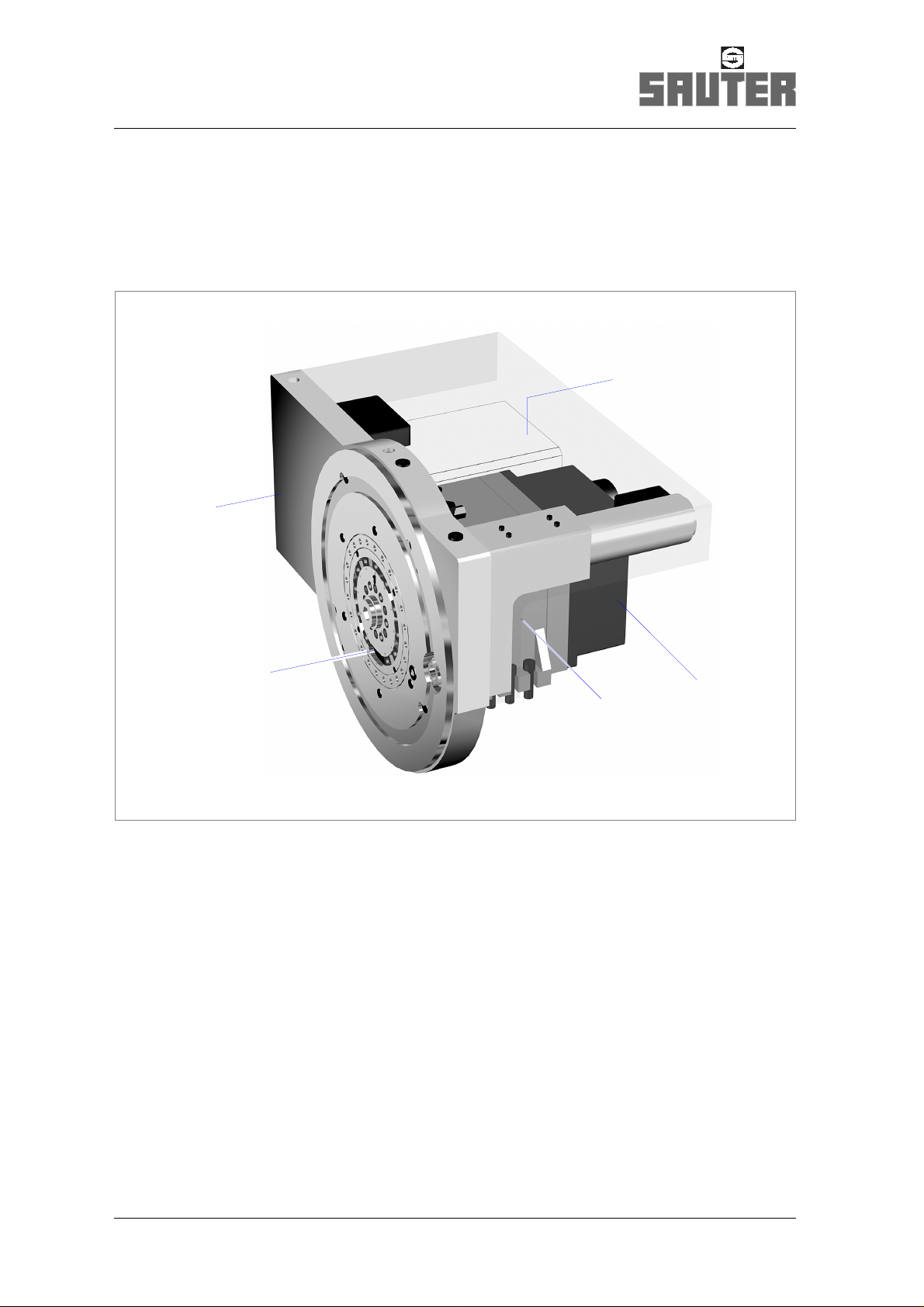
2 Product description
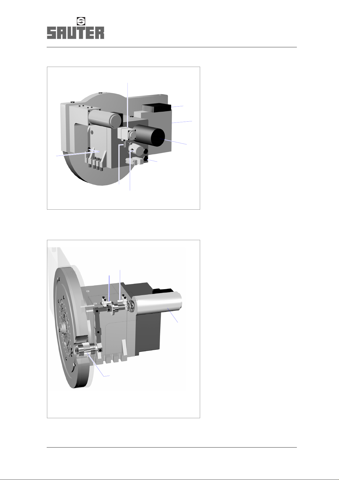
2.1 Designation of parts
2
3
1
4
5
1 Locating disk
2 Tool drive unit: gear housing
3 Tool drive motor
1)
4 Covering hood for electric components
5 Turret housing
10
1) not included in scope of delivery
F:\Sauter\FRAME-AR\TD\0-5-473-\eng\Ba892\PB_473520-25.fm
Page 11
Product description
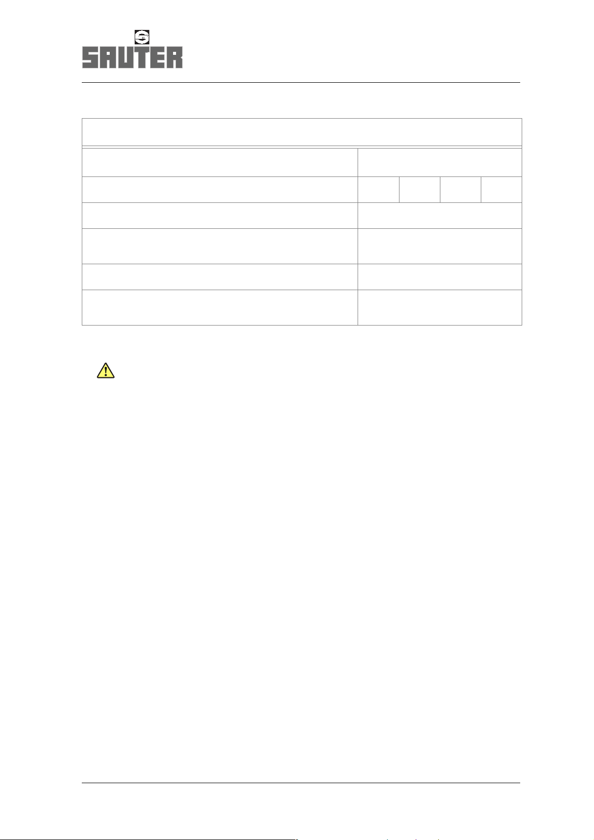
Designation of parts
13
12
6
11
10
6 Solenoid
7 Terminal box:
tool drive motor
7
8
8 Flange plate:
tool drive motor
9 Turret motor
10 Electric connection:
turret
9
11 Angular encoder
12 Proximity switch S7
“Check pre-indexation”
13 Cooling lubricant
cartridge
14
14 Proximity switch S11
“Tool drive
disengaged”
15
15 Proximity switch S10
“Tool drive engaged”
16 Solenoid
17 Tool drive coupling
16
17
F:\Sauter\FRAME-AR\TD\0-5-473-\eng\Ba892\PB_473520-25.fm
11
Page 12

Product description
Technical data 0.5.473.520
2.2 Technical data
Number of indexing positions 8 or 12 or 16
Perm. tangential torque
1)
Nm 3,000
(turret locked)
at calculated safety
Perm. mass moment of inertia of tool disk,
kgm
2
1.3
1.8 – 7.5
2)
tool holders, and tools
Perm. unbalance (load moment) caused
Nm 63
by tool holders and tools
Indexing times
Theoretical cycle time
2)
41 α+
i
s
----------------× 017,× 01,+
n
.
.
(unlock/turn/lock)
at rotating angle α [degrees]
Gear ratio i see turret type plate
Motor speed n rpm see motor rating plate
Perm. indexing frequency min
-1
10 – 5.5
2)
Operating voltage/mains frequency see motor rating plate
Degree of protection IP 65
Turret mass
kg approx. 70
(without tool disk)
Perm. ambient temperature range °C
°F
Operating pressure for cooling lubricant
3)
Cooling lubricant valve – standard version
constant supply
externally switched suppl y
Medium pressure valve (option)
1) The perm. loads refer to processing without load shocks. Whenever processing is
subject to intermittent cuts, shocks or impacts, a significantly reduction in the values
needs to be taken into account.
2) Depending on gear ratio and mains frequency
3) In order to achieve an extended service life of the cooling lubricant valve, it is advisable
to filter the cooling lubricant by ≤ 100µm. Post-connected loads (spindle units with
internal cooling lubricant guide a.o.) may require a higher degree of filter fineness. Note
and comply with the manufacturer’s instructions!
bar
bar
bar
+10 ... +40
+50 ... + 104
7
14
25
F:\Sauter\FRAME-AR\TD\0-5-473-\eng\Ba892\Td_473520.fm
12
Page 13
Product description
Technical data 0.5.473.520
Tool drive
Mass (without any motor) kg approx. 40
1)
Gear ratio i 41/41 41/31 41/27 41/21
2)
Perm. speed
on tool drive coupling n
Max. perm. torque
2) 3)
perm
M
perm
rpm 4000
Nm 32
on tool drive coupling
Transferable power
2)
P
perm
kW 10
Suitable for spindle units
coupling profile 17 × 14 DIN 5482
1) The data stated here may differ on special versions.
2) M
3) The permissible torque can be utilized for non-pulse machining operations.
is the permissible peak load for the gears.
perm
The torque must be limited on the motor frequency converter to the value
indicated, while adhering to the gear ratio involved!
The useful power data depend on the performance characteristic curve of the motor type
used.
For strongly pulsed machining operations - e.g. inserted tooth milling cutters and others only a significantly reduced drive torque should be applied to protect the gears against
any overloads.
F:\Sauter\FRAME-AR\TD\0-5-473-\eng\Ba892\Td_473520.fm
13
Page 14
Manual mode
3 Manual mode
In manual mode, the me chanical functions of the disk-type tool
turret will be checked:
• following initial assembly to the machine
• during troubleshooting
• after a renewed setup following fault conditions
Clearing required prior to any work:
°
Switch the machine off.
°
Push the motor prote cti on s witc h f or t he tu rret i nto th e
OFF p os ition.
1. Undo fixing screws of covering hood,
withdraw covering hood to rear.
If necessary, use push-off screw.
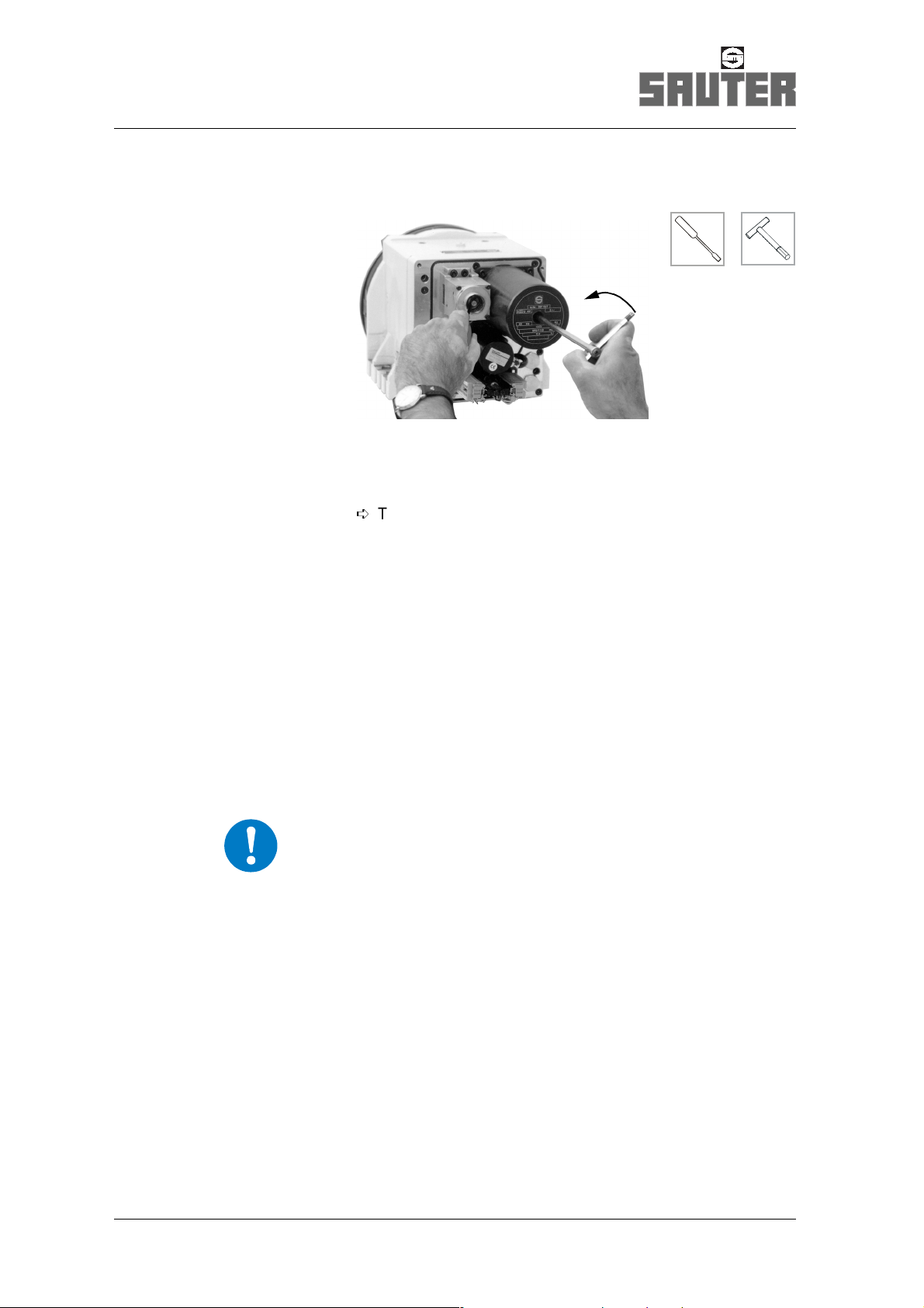
2. Remove screw plug on motor housing.
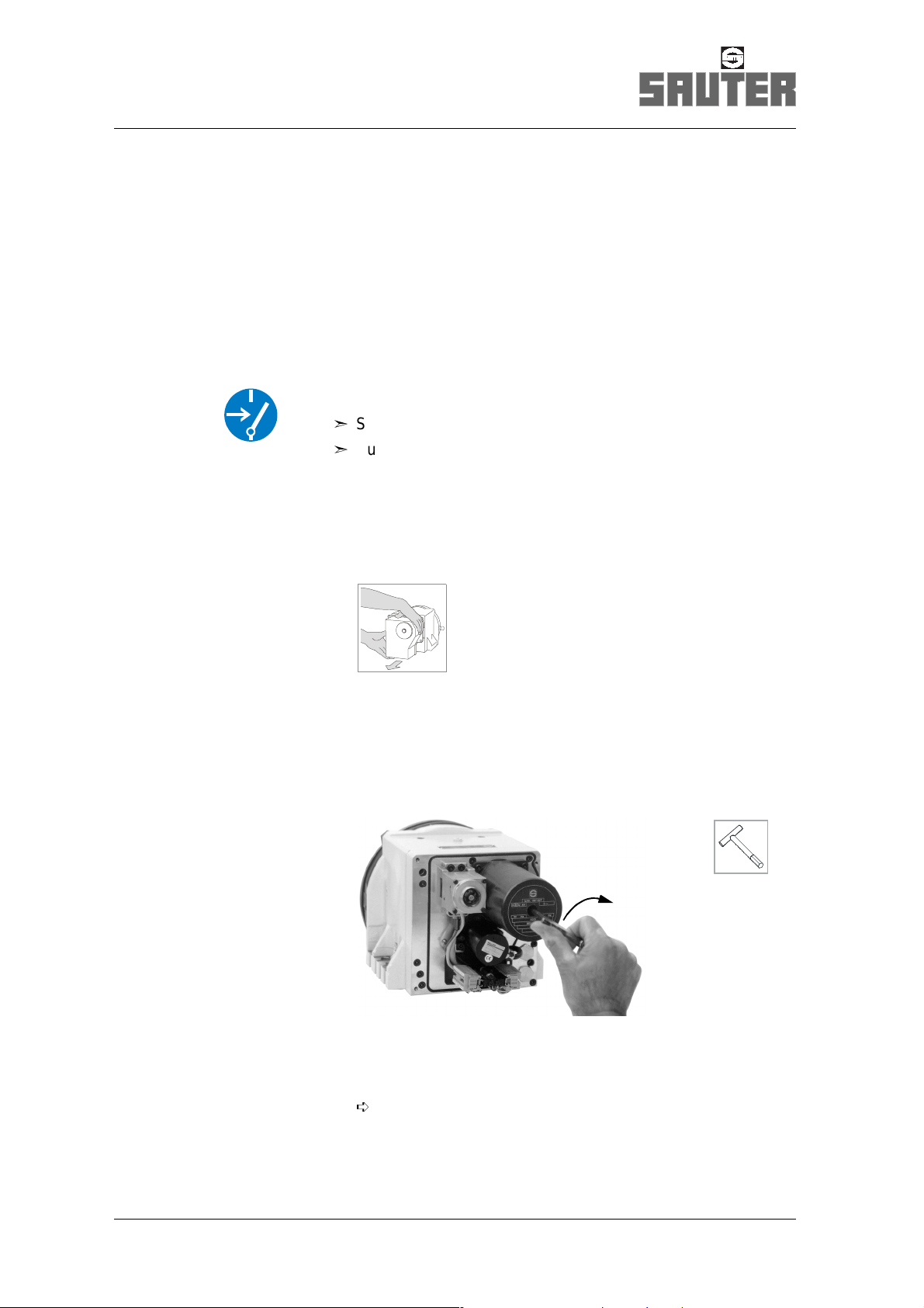
Unlock turret
3. Use a hexagonal pin wrench, complete with T-grip, to rotate
the motor shaft.
·
If the disk-type tool turret is locked, the locating disk (or
tool disk) does no t co-rotat e; the centre position of t he lock
can be felt.
14
F:\Sauter\FRAME-AR\TD\0-5-473-\eng\Ba892\HB_480.fm
Page 15
Manual mode
WARNING
A reversal of the m ome nt o f t he m oto r re su lts in th e
acceleration of the motor shaft. The hexagonal pin wrench may
thus be unexpectedly accelerated.
Therefore, in order to avoid the ejection of the hexagonal pin
wrench and resu lti ng in juri es , fi rm ly grip the hexagonal pin
wrench.
4. Keep the same direction of rotation, continue to rotate.
·
The disk-type tool tur ret unlo cks; a r eversal o f the mo ment
on the motor shaft can be felt.
Rotate tool di sk
F:\Sauter\FRAME-AR\TD\0-5-473-\eng\Ba892\HB_480.fm
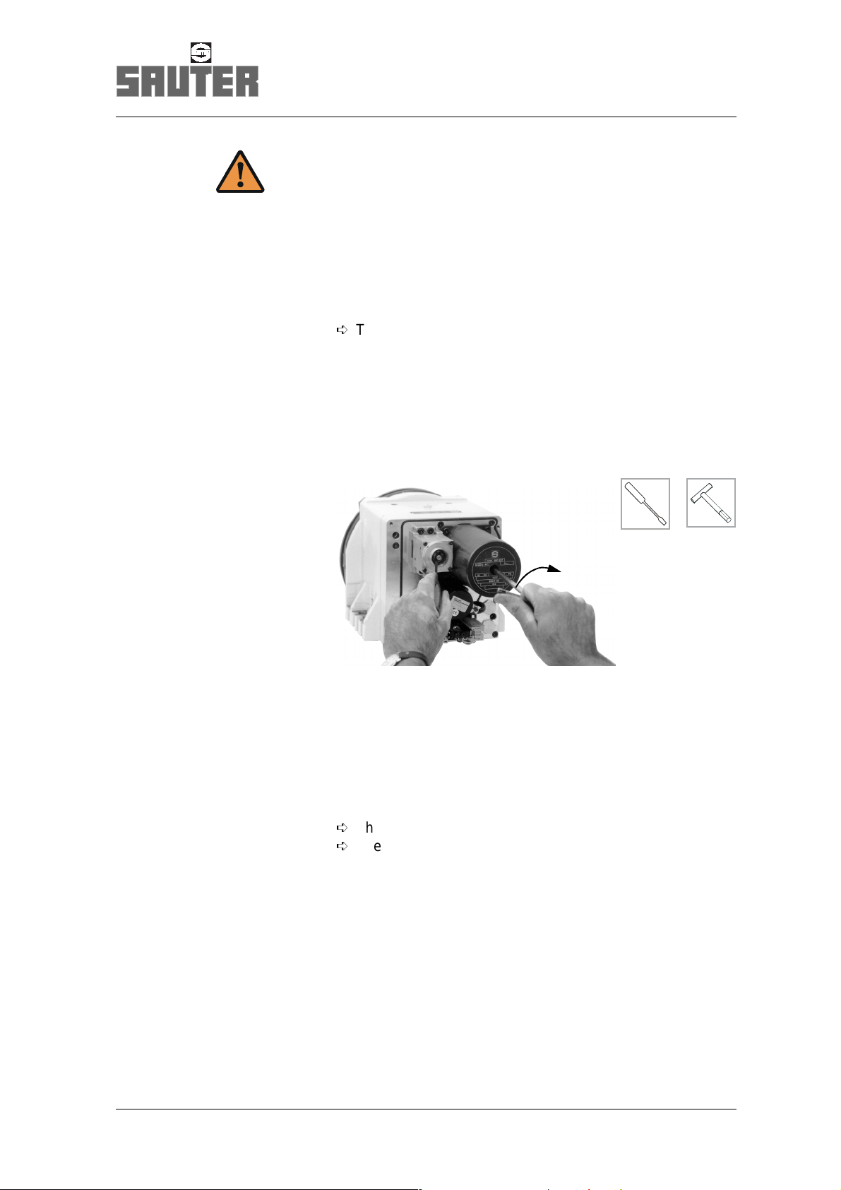
5. Keep direction of rotation, continue to rotate disk until
locating disk (or tool disk) starts to turn as well.
6. Keep direction of rotation, continue to rotate disk until
locating disk (or tool disk) has reached the position r equired,
then press in the keeper by means of a screwdriver.
·
The preindexing bolt engages into a hole.
·
The tool disk cannot be rotated any further.
15
Page 16
Manual mode
Lock turret
7. Reverse direction of rotation on the motor shaft whilst
simultaneously pressing in keeper.
·
The disk-type tool turret locks.
The lock resistance can be felt when rotation is continued.
The locking process ends, if t he centr e pos ition o f the lock
can be felt.
On completion of setup or maintenance work:
8. Screw in plug and fit covering hood.
Note position of cables in order to avoid any pinching of the
same.
Lock turret in position 1
IMPORTANT
For some setup and mai nte nanc e work th e disk -type tool tu rret
has to be locked in position 1.
Precondition
• Numeral 1 of the locating disk has reached its 12 o’clock
position relative to the turret base area.
or
• Position 1 of the tool disk is in working position .
16
1. Use a hexagonal pin wrench, complete with T-grip, and
rotate the motor shaft until position 1 has been reached.
2. Press in the keeper by means of a screwdriver and rotate the
motor shaft until the disk-type tool turret locks (see above).
F:\Sauter\FRAME-AR\TD\0-5-473-\eng\Ba892\HB_480.fm
Page 17

4 Maintenance
Turret maintenance compri ses the followin g tasks:
• Cleaning,
• Checking,
• Setting and
• Repair.
The service life of the turret is approx. 2–3 million switchings
or approx. 5 years.
The service life of the tool drive unit is
approx. 8000 operating hours.
These values appl y to
• collision-free operation,
Maintenance
Safety note s
• compliance with the specified operating conditions and the
permissible loa ds ,
¢
Technical data, page 12
4.1 Safety notes
¢
Page 7
F:\Sauter\FRAME-AR\TD\0-5-473-\eng\Ba892\IH_SI_Zeit_480-473.fm
17
Page 18
Maintenance
Service intervals
4.2 Service intervals
Plan your tasks car efully in order to provide fo r troublefree o peration an d
reduce necessar y downtimes to a minimum.
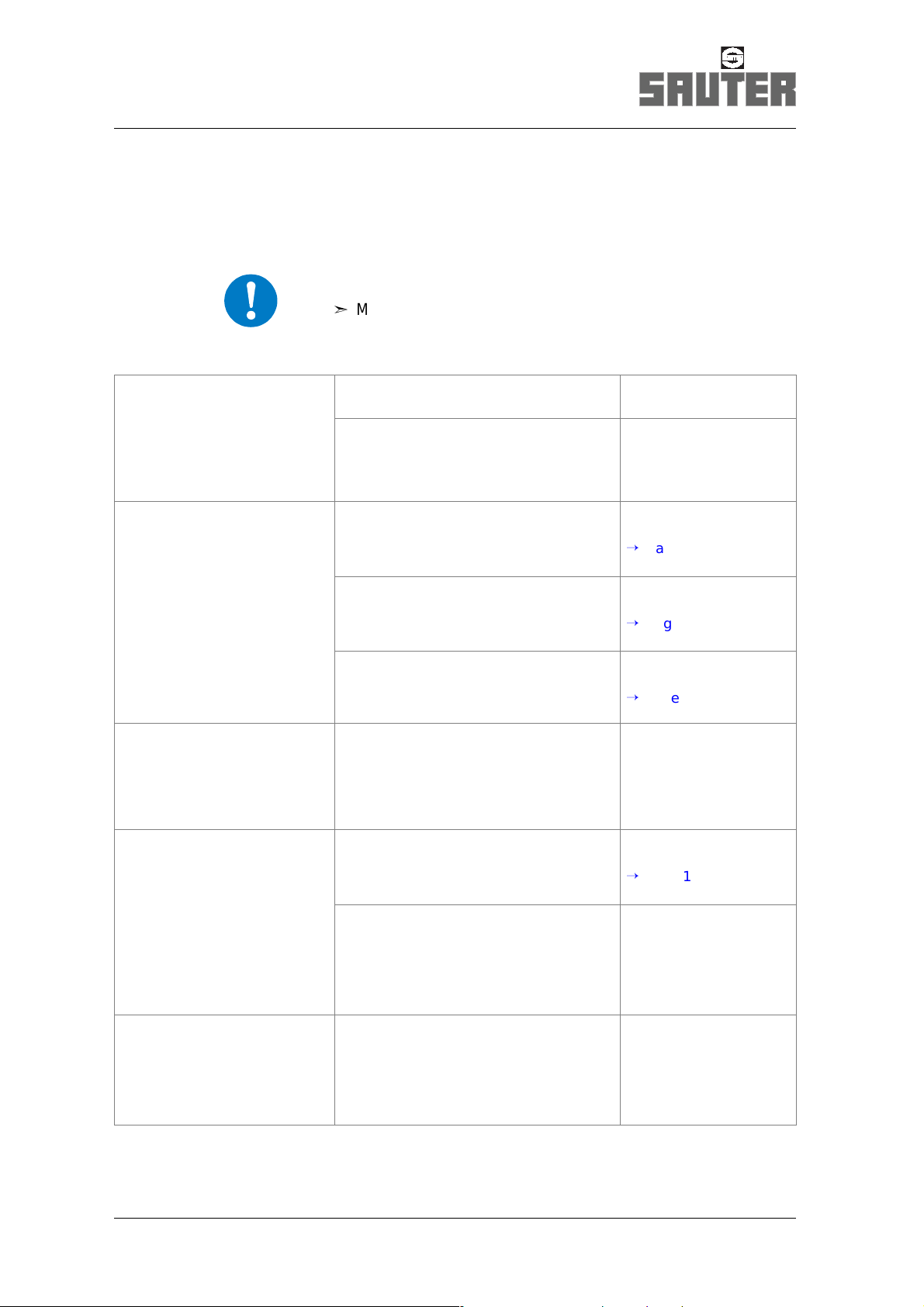
IMPORTANT
°
Maintenance intervals must be adapted
to the operating conditions involved.
if required
after 4000 operatin g hours
of the machine
respectively
after 2½ years
respectively
after 8000 operating hours
of the machine
respectively
Clean tool drive coupling. User
Check tool drive coupling for d amage,
User
replace if necessary.
SAUTER Service
Check cooling lubricant valve for wear
and leakage.
Replace any defective parts.
Check oil of the turret gearbox
User
¢
Page 26
User
chamber;
¢
if necessary, replenish oil.
Check grease condition of tool drive
unit; if necessary, replenish grease.
Check all electrical lines and
Page 19
User
¢
Page 21
User
connections for mechanical damage as
well as embrittlement.
Replace any defective parts.
Change the oil of the turret gearbox
Specialist electrical
engineer
User
chamber.
¢
Page 19
1)
after approx. 2–3 million
indexing operations
respectively
18
The service life of the tool drive unit
SAUTER Service
may possibly be reach ed, depend ing
on the operating conditions involv ed.
A general overhaul is recommende d
for further trouble-free operation.
The service life of the turret may
SAUTER Service
possibly be reached, depending on the
operating conditions involved.
A general overhaul is recommende d
for further trouble-free operation.
1) These are persons who are able to identify risks and to prevent possible hazards
on the basis of their special training and their experience
(IEC 60 201-1).
F:\Sauter\FRAME-AR\TD\0-5-473-\eng\Ba892\IH_SI_Zeit_480-473.fm
Page 19
4.3 Maintenance work
Turret gearbox chamber
The turret gearbox chamber ha s to be service d after 4,00 0 operating hou rs.
Clearing required prior to any work:
°
Switch the machine off.
°
Push the motor pro te cti on switch for the turret into the
OFF po s itio n.
IMPORTANT
Improperly disposed used oil is a danger for our environment.
°
Pay attention to the le ga l re gu lat ion s for the waste disposal
of used oil.
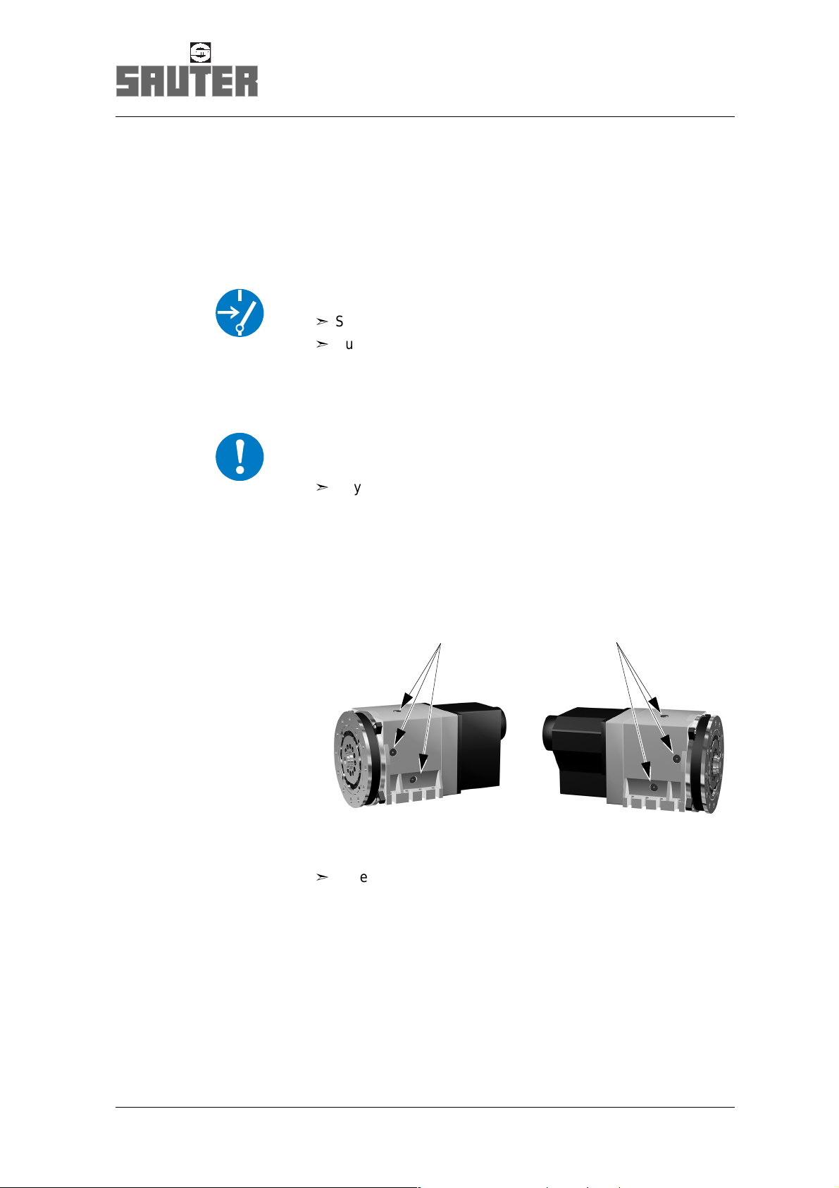
Maintenance work
Turret gearbox chamber
In line with the setup position of the disk-type tool tur ret, the
following apertures (1) for draining or replenishing oil are
provided:
11
Checking the oil
°
Carefully unsc rew o il dra in plu g and drain the oil
(max. 10 cm
3
) into a suitable co ntainer.
F:\Sauter\FRAME-AR\TD\0-5-473-\eng\Ba892\IH_Oel_Rev_480516-20-25.fm
19
Page 20
Maintenance work
Turret gearbox chamber
Assess oil condition
Condition Cause Action
Oil black or brow n, w ith ou t
metallic abrasi on
Oil black or brown, with
metallic abrasi on
Oil white, mixed with cooling
lubricant
Natural consum p tion –
Internal parts of turret are
damaged
Turret sealings are damage d
None oil left Turret sealings are damaged
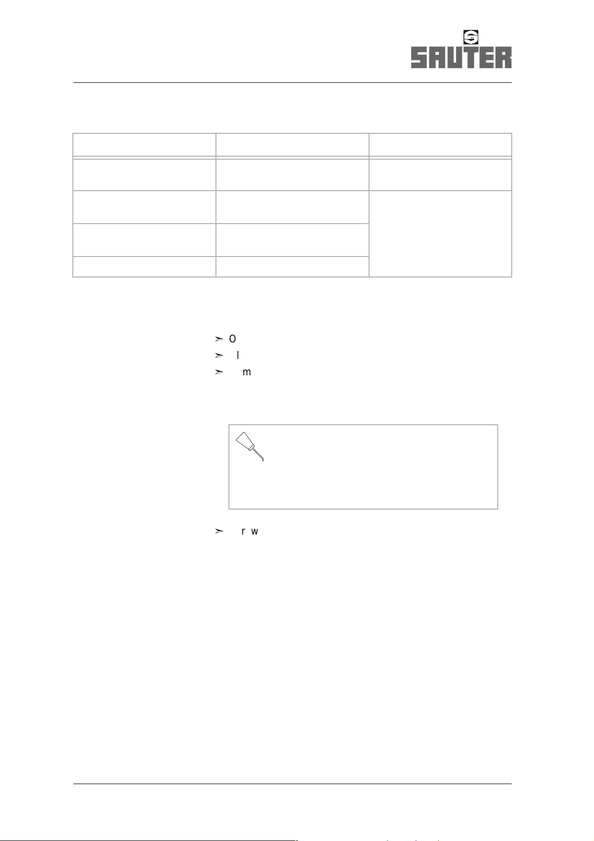
Changing the oil
°
Open oil drai n p lu g, drain waste oil.
°
Close oil drain plug.
°
Remove screw plug from oil charging hole.
Fill oil
300cm
3
Request SAUTER Service!
lubricating oil C acc. to ISO 6743/ 6
viscosity ISO VG 46 acc. to DIN 51562
°
Screw in screw plug.
20
F:\Sauter\FRAME-AR\TD\0-5-473-\eng\Ba892\IH_Oel_Rev_480516-20-25.fm
Page 21

Maintenance work
Tool drive
The tool drive is lubricated with grease.
The grease needs t o be checked a fter 4,000 h ours of opera tion
of the tool drive.
Clearing required prior to any work:
°
Switch the machine off.
°
Push the motor pro te cti on switch for the turret into the
OFF po s itio n.
Preparation
°
Provide access to the ap e rtu re (1) on the tool drive.
Tool drive
1
Checking the grease condit ion
°
Unscrew screw plug on aperture (1).
°
Rotate gear and assess grease condition:
Condition Cause Measure
No grease visible on gear Natural consumption Replenish grease.
Grease: blac k or b r own ,
without metallic a bra s ion
Grease: blac k or b r own ,
with metallic abra si on
cooling lubrican t
Traces of natural wear –
Internal parts of turret are
damaged
Turret sealings are damag ed
Request SAUTER Service!Grease: whi te, mixed with
Grease mixe d wi th oil Turret sealings are d am ag ed
Replenishing the grease
F:\Sauter\FRAME-AR\TD\0-5-473-\eng\Ba892\IH_Fett_WZA_473.fm
3
°
Close aperture (1) by means of screw plug.
ISOFLEX NBU 15max. 20cm
(KLÜBER)
21
Page 22

Repairs after fault conditions
Possible faults and remedies
4.4 Repairs after fault conditions
Clearing required prior to any work:
°
Switch the machine off.
°
Push the motor prote cti on sw itc h f or t he tu rret i nto th e
OFF p os ition.
Fault Cause Remedy Who carries out
this task?
Turret
Incorrect center height,
tool disk offset relative
to locating disk
Tool disk does not
rotate
Turret is difficult to
operate
(Thermo protection
device has responded)
Turret no longer locks
or the pre-indexing bolt
gets caught
Tool disk does not stop
in the selected position
Collision when turret is
locked
Gearwheels are
defective
Proximity switch S11
does not switch
Insufficient oil in the
gearbox chamber
Contactor is defective Check motor drive
Collision during
pivoting
Angular encoder is not
correctly adjusted or
defective
Turn back tool disk in
the annular groove and
align
SAUTER
Service
Check proximity switch
S11; if necessary, set
or replace
Check oil
SAUTER
Service
Check angular
encoder, set or replace
if necessary
User
¢
Page 25
User
¢
Page 37
User
¢
Page 19
User
User
¢
Page 27,
page 29
22
Proximity switch S7
does not switch
Check proximity switch
S7, set or replace if
necessary
User
¢
Page 33
F:\Sauter\FRAME-AR\TD\0-5-473-\eng\Ba892\IH_Stör_480-473.fm
Page 23

Repairs afte r fault conditions
Possible fa u lts and remedies
Fault Cause Remedy Who carries out
this task?
Tool disk stops in
between two positions
Chips between tool
disk and turret
Remove tool disk,
remove chips
Leakage oil escapes Seals are defective SAUTER
Service
Cooling lubricant is not
being transferred
Cooling lubricant
escapes between tool
Cooling lubricant valve
is defective
Cooling lubricant valve/
line is blocked
Cooling lubricant valve
is defective
Replace cooling
lubricant valve
Blow cooling lubricant
valve/line clear
Replace cooling
lubricant valve
disk and turret
Tangential play of tool
disk when turret is
Collision while turret is
locked
SAUTER
Service
locked
Wear due to lack of oil
User
User
¢
Page 26
F:\Sauter\FRAME-AR\TD\0-5-473-\eng\Ba892\IH_Stör_480-473.fm
23
Page 24

Repairs after fault conditions
Possible faults and remedies
Fault Cause Remedy Who carries out
this task?
Tool drive
Tool drive does not
Tool disk is displaced Align tool disk
engage
Tool drive coupling is
defective
Pinion shaft is
defective
Solenoid is defective Replace solenoid and
Tool is not driven Gearwheels are
defective
Tool drive motor is
defective
Proximity switch S10
does not switch
SAUTER
Service
Replace defective
part,
adjust solenoid
adjust
SAUTER
Service
Replace tool drive
motor
Check proximity switch
S10, set or replace if
necessary
User
¢
Page 25
User
¢
Page 36
User
User
¢
Page 37
24
F:\Sauter\FRAME-AR\TD\0-5-473-\eng\Ba892\IH_Stör_480-473.fm
Page 25

4.5 Aligning the tool disk
Preparation
Clearing required prior to any work:
°
Switch the machine off.
°
Push the motor pro te cti on switch for the turret into the
OFF po s itio n.
°
Lock turret.
¢
Manual mode, page 14
Aligning
Repairs a fte r fa u lt conditions
Aligning the tool disk
1
1
°
If necessary, undo screws (1).
°
Align the locating hole to center height of the machine;
use a plug gaug e (2 ) if required.
°
Tighten screws (1).
M10 - 12.9 77 Nm
F:\Sauter\FRAME-AR\TD\0-5-473-\eng\Ba892\IH_Ausr_WS_480-473.fm
MoS
2
25
Page 26

Repairs after fault conditions
Replacing the cooling lubricant valve
4.6 Replacing the cooling lubricant valve
The cooling lubri cant valve is a wearing pa rt and has to be serviced after
4,000 hours of opera tion.
Clearing required prior to any work:
°
Switch the machine off.
°
Push the motor prote cti on s witc h f or t he tu rret i nto th e
OFF p os ition.
Checking
Check whethe r c oo lin g lub ric ant emerges between tool dis k
and turret.
°
If necessary, replace defective parts or the entire cooling
lubricant valve.
1)
1
2
3
Replacing
°
Undo screw plug (3).
°
Withdraw coolin g l ub ric ant cartridge complete with
screw plug (3).
°
Check cooling lubricant cartridge; if necessary, replace
bushing (1) and O-ring seal (2).
°
Refit cooling lubricant cartridge complete with screw plug.
26
1) Customized versions may also differ from the present version.
F:\Sauter\FRAME-AR\TD\0-5-473-\eng\Ba892\IH_KSS_WZA.fm
Page 27

Repairs a fte r fa u lt conditions
Adjusting the angular encoder
4.7 Adjusting the angular encoder
IMPORTANT
Setting tasks require a 24V D C power sup ply.
Preparation
°
Lock disk-type tool turret in position 1.
¢
Manual mode, page14
°
Undo claws by means of a hexagonal pin wrench.
Adjusting
°
Rotate angular encoder out of position until illuminated diode
lights up.
°
Clamp in angular encoder by means of the claws.
F:\Sauter\FRAME-AR\TD\0-5-473-\eng\Ba892\IH_Einstell_WPG_4805xx.fm
27
Page 28

Repairs after fault conditions
Adjusting the angular encoder
Checking the setup for symmetr y
1. Use hexagonal pin wrench with T-grip for rotating the motor
2. Rotate motor shaft until illuminated diode on the angu lar
shaft.
encoder or the indication “Position 1” on the machine are
extinguished.
3. Note the T-grip position.
WARNING
A reversal of the m om e nt of the m oto r re su lts in th e
acceleration of the mot or shaft . The hexag onal pin wr ench may
thus be unexpectedly accelerated.
Therefore, in order to avoid the ejection of the hexagonal pin
wrench and resu lti ng in ju ries , firmly grip the hexagonal pin
wrench.
4. Carefully continue to rotate until a moment reversal can be
felt on the motor shaft.
5. Note the T-grip position.
The distance between the two grip positions characterizes the
angle range.
6. Repeat steps 1 to 5 with reverse direction of rotation. The
α must be the same for both directions of rotation!
angle
28
By turning the angular encoder out of position, any
dissymmetry can be removed.
F:\Sauter\FRAME-AR\TD\0-5-473-\eng\Ba892\IH_Einstell_WPG_4805xx.fm
Page 29

Repairs a fte r fa u lt conditions
Replacing the angular encoder
4.8 Replacing the angular encoder
The location of the a ngular encoder depends on t he disk-typ e tool turret
version (without /with flui d rotary fee dthrough).
IMPORTANT
Setting tasks require a 24V D C power sup ply.
Angular encoder, centrally positioned
Preparation
°
Lock disk-type tool turret in position 1.
¢
Manual mode, page 14
1
2
3
°
Note the position of the c ab le ou tle t (2 ) on th e
angular encoder (1), remove attachment.
°
Undo cables (3) on te rm ina l s tri p (n ote wh ere th ey a r e
connected).
F:\Sauter\FRAME-AR\TD\0-5-473-\eng\Ba892\IH_Ausw_WPG_480520-25.fm
°
Undo claws by means of a hexagonal pin wrench.
29
Page 30

Repairs after fault conditions
Replacing the angular encoder
Replacing
°
°
°
Undo setscrew.
Carefully withdraw angular encoder.
Connect new angular encoder electrically.
¢
Wiring diagram: D is k -t ype too l tu rr et EP - 87 0
in the appendix to these Operating Instructions.
°
Rotate shaft of the angular encoder until the illumination of
the LED on the angular encoder indicates the “Position 1”
setting.
This indication must remain whilst the following steps are
carried out.
IMPORTANT
The LED is used o nly to in d ica te po sition 1 during the
adjustment work. It is no position indicator during operation.
°
Ensure that the cable outlet is in its correct position.
30
F:\Sauter\FRAME-AR\TD\0-5-473-\eng\Ba892\IH_Ausw_WPG_480520-25.fm
Page 31

Repairs a fte r fa u lt conditions
Replacing the angular encoder
°
Insert the shaft o f th e a ng ul ar enc o de r in to the bore of the
flexible shaft an d introduce carefully until the an gu la r
encoder is in contact with the plate. Ensure that the claws
are in their correct position!
°
Use setscrew to attach the angular encoder to the shaft.
°
If necessary, check the adjustment of the angular encoder.
¢
Page 28
°
Use claws to secure the angular encoder.
°
Fit covering hood. Note position of cables in order to avoid
any pinching of the same.
Angular encoder, in side position
Preparation
°
Lock disk-type tool turret in position 1.
¢
Manual mode, page 14
1
23
°
Note the position of the cable outlet (2) on the angular
encoder (3), remove attachment.
°
Undo cables (1) on te rm ina l s tri p (n ote wh ere th ey a r e
connected).
Replacing
F:\Sauter\FRAME-AR\TD\0-5-473-\eng\Ba892\IH_Ausw_WPG_480520-25.fm
°
Undo claws by means of a hexagonal pin wrench.
31
Page 32

Repairs after fault conditions
Replacing the angular encoder
°
°
°
Carefully withdraw angular encoder.
On the shaft of the angul ar encoder, a disk is locate d which is
fixed in position by means of a setscrew.
Undo setscrew and remove disk.
Connect new angular encoder electrically.
¢
Wiring diagram: D is k -t ype too l tu rr et EP - 87 0
in the appendix to these Operating Instructions.
°
Rotate shaft of the angular encoder until the illumination of
the LED on the angular encoder indicates the “Position 1”
setting.
This indication must remain whilst the following steps are
carried out.
°
Fit disk in its correct position.
°
Ensure that the cable outlet is in its correct position.
°
Insert the angula r en c od er i nto th e op en ing o f th e p la te,
note the position of the claws!
°
If necessary, check the adjustment of the angular encoder.
¢
Page 28
32
°
Use claws to secure the angular encoder.
°
Fit covering hood. Note position of cables in order to avoid
any pinching of the same.
F:\Sauter\FRAME-AR\TD\0-5-473-\eng\Ba892\IH_Ausw_WPG_480520-25.fm
Page 33

4.9 Proximi ty s w it ch S7
IMPORTANT
Setting tasks require a 24V D C power sup ply.
Clearing required prior to any work:
°
Switch the machine off.
°
Push the motor pro te cti on switch for the turret into the
OFF po s itio n.
°
Undo fixing screws of covering hood, withdraw covering
hood to rear. If necessary, use push-off screw.
Repairs a fte r fa u lt conditions
Proximity s wit ch S 7
Replacing
2
1
°
Undo clip (3) and withdraw proximity switch (1) from
3
eccentric bushing (2).
F:\Sauter\FRAME-AR\TD\0-5-473-\eng\Ba892\IH_S7_4805xx.fm
33
Page 34

Repairs after fault conditions
Proximity s wit ch S 7
Checking
.
°
°
Adjusting
°
+
brown
11
8
V
24 V
black
blue
−
H-Signal ≥ 90% of rated voltage
Apply a voltage of 24 V DC to the proximity sw itc h (1).
The proximity switch is energized when the LED lights up.
Insert tested/new proximity switch (1).
Unlock disk-type to ol tu rret.
¢
Manual mode, page14
°
Move disk-type tool turret into a location between two
positions.
If the keeper (M) is operated, the preindexing bolt (4) can be
pressed in pa rtia lly o nl y.
a
5
4
M
°
Set switching distance x = 0.3 – 0.5 mm.
°
Determine dimension a.
x
2
3
1
34
a = stroke of the preindexing bolt (4) up to the damping
ring (5) when the so le no id is op erated manually
(corresponds to the press-in depth of the keeper (M)).
F:\Sauter\FRAME-AR\TD\0-5-473-\eng\Ba892\IH_S7_4805xx.fm
Page 35

Repairs a fte r fa u lt conditions
Proximity s wit ch S 7
°
Adjust proximity switch (1) on eccentric bushing (2) such that
its signal begins to drop after a + 2
+0.5
mm immersion depth
of the preindexing bolt.
Any greater immers io n de pth m ay cau se th e mo to r to be
blocked.
°
Tighten clip (3).
°
Fit covering hood. Note position of cables in order to avoid
any pinching of the same.
Function test
°
Switch on turret.
°
Check switch in g process repeatedly.
F:\Sauter\FRAME-AR\TD\0-5-473-\eng\Ba892\IH_S7_4805xx.fm
35
Page 36

Repairs after fault conditions
Solenoid
4.10 Solenoid
The solenoid deter mines the engagemen t path. The co upling end p ositions
are controlled b y mean s of t he prox imity s witches S 10 “Tool drive engaged”
and S11 “Tool drive disengaged”.
Clearing required prior to any work:
°
°
Preparation
°
If a tool disk is f itte d, th e tool holder location must be
accessible in working position:
°
Switch the machine off.
Push the motor prote cti on s witc h f or t he tu rret i nto th e
OFF p os ition.
If necessary, remove the covering hood on the tool drive unit.
If necessary, disassemble tool ho ld er.
1
3
5
Replacing
°
Remove screws (1) on the flange plate of the soleno id (2).
°
Undo setscrew (5).
°
Replace the solenoid(2) c omplete with adjusting nut(3) and
4
2
bushing (4).
°
Tighten screws (1).
36
F:\Sauter\FRAME-AR\TD\0-5-473-\eng\Ba892\IH_Mag_WZA073.fm
Page 37

~1mm
Repairs a fte r fa u lt conditions
Solenoid
Checking
Is the clearance from t he pinion shaft (10) to the edge of the
spindle unit coupling (11) 1mm when the keeper is drawn out?
°
If necessary, adjust final coupling position.
67 8 9
0.3-0.5mm
53
1011
Adjusting the final coupling position
°
Undo setscre w (5).
°
Undo adjusting nut (3) and rotate keeper.
°
Adjust clearan ce.
°
Tighten setscrew (5).
Adjusting the proximity switches
°
Undo screws (8) of clip (7).
°
Adjust proximity switch S11 (6) to a clearanc e of 0. 3 - 0.5 mm
relative to its switching area.
°
Tighten screws (8) of clip(7 ).
°
Adjust proximit y s w itc h S10 (9) in the same wa y.
F:\Sauter\FRAME-AR\TD\0-5-473-\eng\Ba892\IH_Mag_WZA073.fm
37
Page 38

Replacement parts
5 Replacement parts
IMPORTANT
Only use the order form if you wish to order
any replacement parts!
A
B
38
F:\Sauter\FRAME-AR\TD\0-5-473-\ger\Ba892\E_Übersicht_473520_BA-892.fm
Page 39

Replacement parts
A Replacement parts for turrets (without tool drive)
¢
Indexing, page 40
¢
Clamping and angular encoder, page 41
¢
Gear, drive, pre-indexation, page 4 2
B Replacement parts tool drive for turret
¢
0.5.473.520 - 107 468
- 110 660
0.5.473.520 - 111 092
- 111 432
- 112 862
0.5.473.520 - 115 702
Page 44 - 45
¢
Page 46 - 47
¢
Page 48 - 49
¢
Page 50 - 51
¢
Page 52 - 53
¢
Page 54 - 55
- 125 365
-
¢
Page 56 - 57
F:\Sauter\FRAME-AR\TD\0-5-473-\ger\Ba892\E_Übersicht_473520_BA-892.fm
39
Page 40

Replacement parts
Indexing
Indexing
1
2
Setscrew is only applied
and secured (LOCTITE 221)
No. Ident No. Designation Qty.
1 058 073
2 102 048
O-ring seal
Replacements parts group Indexing
1
3
40
IMPORTANT Request assembly guideline MR 02.025!
F:\Sauter\FRAME-AR\TD\0-5-473-\ger\Ba892\E_480520.fm
Page 41

Clamping and angular encoder
Clamping and angular encoder
Replacement parts
1
2
3
4
No. Ident No. Designation Qty.
1 067586 Disk (for tuning) 1
2 063 358
3
O-ring seal
Replacements parts group Clamping
1
1
IMPORTANT Request assembly guideline M R 02.025!
4 105 500
Angular encoder
1
F:\Sauter\FRAME-AR\TD\0-5-473-\ger\Ba892\E_480520.fm
41
Page 42

Replacement parts
Gear, drive, pre-indexation
Gear, drive, pre-indexation
12 5364
42
7
89 10
F:\Sauter\FRAME-AR\TD\0-5-473-\ger\Ba892\E_480520.fm
Page 43

Replacement parts
Gear, drive, pre-indexation
No. Ident No. Designation Qty.
1 071 904
2 078 218
3 069 340
4 063 365
5 065 718
6Motor
7 004 157
8 070 460
9 067 659
10 064 813
Sealing ring
O-ring seal
O-ring seal
O-ring seal
O-ring seal
1) 2)
Proximity switch
Sealing ring
Compression spring
Solenoid
1
1
1
1
1
1
1
1
1
1
1) will be supplied complete with housing and bearing
2) data according to motor’s nameplate
F:\Sauter\FRAME-AR\TD\0-5-473-\ger\Ba892\E_480520.fm
43
Page 44

Replacement parts Tool Drive
for turret 0.5.473.520 - 107 468
for turret 0.5.473.520 - 107 468
6
7
8
5
4
3
2
9
Setscrew is only applied and
secured
(LOCTITE 221)
A
10
B
11
12
44
1
13
14
15
16
(16)
(14)
(15)
F:\Sauter\FRAME-AR\TD\0-5-473-\ger\Ba892\E_473520-107468.fm
Page 45

Replacement parts Tool Drive
for turret 0.5.473.520 - 107 468
0.5.473.520 - 107 468
No. Ident No. Designation Qty.
1036 588
2063 365
3069 657
4068 017
5000 706
Spaghetti hose
O-ring seal
Wire race ball bearing
O-ring seal
Deep groove ball bearing
6 058 548 O-ring seal
058 521 O-ring seal
063 461 O-ring seal
065 993 O-ring seal
7076 749
8118 182
Proximity switch
Solenoid
9 058 495 O-ring seal
059 932 O-ring seal
1) 2) 3) 4)
5)
6)
7)
1) 2) 3) 4) 6) 7)
5)
0.636m
1
1
1
1
1
1
1
1
2
1
1
1
10 034 592
11 058 506
12 A 075 508
12 B 101 121
13 103 530
14 065 138
15 038 494
16 060 663
1) for motor SIEMENS 1FT5 072
2) for motor SIEMENS 1FT5 076
3) for motor SIEMENS 1FT6 084
4) for motor FAGOR FXM 55
5) for motor FANUC alpha 22
6) for motor SIEMENS 1FT5 066
7) for motor FANUC 6S
8) standard version
9) version for medium pressure
FU groove ring
O-ring seal
Cooling lubricant valve, complete
Cooling lubricant valve, complete
Pinion shaft, complete
Radial seal for rotating shaft
Deep groove ball bearing
O-ring seal
1
1
8)
9)
1
1
1
2
2
2
F:\Sauter\FRAME-AR\TD\0-5-473-\ger\Ba892\E_473520-107468.fm
45
Page 46

Replacement parts Tool Drive
for turret 0.5.473.520 - 110 660
for turret 0.5.473.520 - 110 660
6
7
8
5
4
3
2
9
Setscrew is only applied and
secured
(LOCTITE 221)
A
10
B
11
12
46
1
13
14
15
16
(16)
(14)
(15)
F:\Sauter\FRAME-AR\TD\0-5-473-\ger\Ba892\E_473520-110660.fm
Page 47

Replacement parts Tool Drive
for turret 0.5.473.520 - 110 660
0.5.473.520 - 110 660
No. Ident No. Designation Qty.
1036 588
2067 810
3068 207
4064 594
5000 706
Spaghetti hose
O-ring seal
Wire race ball bearing
O-ring seal
Deep groove ball bearing
6 058 075 O-ring seal
058 548 O-ring seal
058 521 O-ring seal
065 993 O-ring seal
7076 749
8118 182
Proximity switch
Solenoid
9 058 521 O-ring seal
065 993 O-ring seal
1)
2)
3)
4) 5) 6)
3) 6)
1) 2) 4) 5)
0.636m
1
1
1
1
1
1
1
1
2
1
1
1
10 034 592
11 058 506
12 A 075 508
12 B 101 121
13 103 778
14 065 138
15 038 494
16 060 663
1) for motor FANUC 2S
2) for motor SIEMENS 1FT5 072
3) for motor FANUC alpha M12
4) for motor SIEMENS 1FT6 064
5) for motor INDRAMAT MDD 93A
6) for motor FANUC alpha M12/4000HVi
7) standard version
8) version for medium pressure
FU groove ring
O-ring seal
Cooling lubricant valve, complete
Cooling lubricant valve, complete
Pinion shaft, complete
Radial seal for rotating shaft
Deep groove ball bearing
O-ring seal
1
1
7)
8)
1
1
1
2
2
2
F:\Sauter\FRAME-AR\TD\0-5-473-\ger\Ba892\E_473520-110660.fm
47
Page 48

Replacement parts Tool Drive
for turret 0.5.473.520 - 111 092
for turret 0.5.473.520 - 111 092
6
7
8
5
4
3
2
9
Setscrew is only applied and
secured
(LOCTITE 221)
A
10
B
11
12
48
1
13
14
15
16
(16)
(14)
(15)
F:\Sauter\FRAME-AR\TD\0-5-473-\ger\Ba892\E_473520-111092.fm
Page 49

Replacement parts Tool Drive
for turret 0.5.473.520 - 111 092
0.5.473.520 - 111 092
No. Ident No. Designation Qty.
1036 588
2063 365
3069 657
4068 017
5000 706
Spaghetti hose
O-ring seal
Wire race ball bearing
O-ring seal
Deep groove ball bearing
6 058 075 O-ring seal
058 548 O-ring seal
065 993 O-ring seal
7076 749
8118 182
Proximity switch
Solenoid
1)
2)
3)
0.636m
9 059 932 O-ring seal 1
10 034 592
11 058 506
FU groove ring
O-ring seal
1
1
1
1
1
1
1
2
1
1
1
12 A 075 508
12 B 101 121
13 104 127
14 065 138
15 038 494
16 060 663
1) for motor FANUC alpha 3
2) for motor SIEMENS 1FT6 082
3) for motor FANUC alpha 1,5
4) standard version
5) version for medium pressure
Cooling lubricant valve, complete
Cooling lubricant valve, complete
Pinion shaft, complete
Radial seal for rotating shaft
Deep groove ball bearing
O-ring seal
4)
5)
1
1
1
2
2
2
F:\Sauter\FRAME-AR\TD\0-5-473-\ger\Ba892\E_473520-111092.fm
49
Page 50

Replacement parts Tool Drive
for turret 0.5.473.520 - 111 432
for turret 0.5.473.520 - 111 432
6
7
8
5
4
3
2
9
Setscrew is only applied and
secured
(LOCTITE 221)
A
10
B
11
12
50
1
13
14
15
16
(16)
(14)
(15)
F:\Sauter\FRAME-AR\TD\0-5-473-\ger\Ba892\E_473520-111432.fm
Page 51

Replacement parts Tool Drive
for turret 0.5.473.520 - 111 432
0.5.473.520 - 111 432
No. Ident No. Designation Qty.
1036 588
2063 365
3069 657
4068 017
5000 706
Spaghetti hose
O-ring seal
Wire race ball bearing
O-ring seal
Deep groove ball bearing
6 058 548 O-ring seal
058 521 O-ring seal
063 461 O-ring seal
065 993 O-ring seal
7076 749
8118 182
Proximity switch
Solenoid
9 058 495 O-ring seal
059 932 O-ring seal
1) 2) 3)
4)
5)
6)
1) 2) 3) 5) 6)
4)
0.636m
1
1
1
1
1
1
1
1
2
1
1
1
10 034 592
11 058 506
12 A 075 508
12 B 101 121
13 103 530
14 065 138
15 038 494
16 060 663
1) for motor SIEMENS 1FT5 072
2) for motor SIEMENS 1FT5 076
3) for motor SIEMENS 1FT6 084
4) for motor FANUC alpha 22
5) for motor SIEMENS 1FT5 066
6) for motor FANUC 6S
7) standard version
8) version for medium pressure
FU groove ring
O-ring seal
Cooling lubricant valve, complete
Cooling lubricant valve, complete
Pinion shaft, complete
Radial seal for rotating shaft
Deep groove ball bearing
O-ring seal
1
1
7)
8)
1
1
1
2
2
2
F:\Sauter\FRAME-AR\TD\0-5-473-\ger\Ba892\E_473520-111432.fm
51
Page 52

Replacement parts Tool Drive
for turret 0.5.473.520 - 112 862
for turret 0.5.473.520 - 112 862
6
7
8
5
4
3
2
9
Setscrew is only applied and
secured
(LOCTITE 221)
A
10
B
11
12
52
1
13
14
15
16
(16)
(14)
(15)
F:\Sauter\FRAME-AR\TD\0-5-473-\ger\Ba892\E_473520-112862.fm
Page 53

Replacement parts Tool Drive
for turret 0.5.473.520 - 112 862
0.5.473.520 - 112 862
No. Ident No. Designation Qty.
1 036 588 Spaghetti hose 0.636 m
2063 365
3069 657
4068 017
5000 706
6 058 075 O-ring seal
058 548 O-ring seal
065 993 O-ring seal
7076 749
8118 182
O-ring seal
Wire race ball bearing
O-ring seal
Deep groove ball bearing
1)
2)
3)
Proximity switch
Solenoid
9 059 932 O-ring seal 1
10 034 592
11 058 506
12 A 075 508
FU groove ring
O-ring seal
Cooling lubricant valve, complete
4)
1
1
1
1
1
1
1
2
1
1
1
1
12 B 101 121
13 104 127
14 065 138
15 038 494
16 060 663
1) for motor FANUC alpha 3
2) for motor SIEMENS 1FT6 082
3) for motor FANUC alpha 1,5
4) standard version
5) version for medium pressure
F:\Sauter\FRAME-AR\TD\0-5-473-\ger\Ba892\E_473520-112862.fm
Cooling lubricant valve, complete
Pinion shaft, complete
Radial seal for rotating shaft
Deep groove ball bearing
O-ring seal
5)
1
1
2
2
2
53
Page 54

Replacement parts Tool Drive
for turret 0.5.473.520 - 115 702
for turret 0.5.473.520 - 115 702
6
7
8
5
4
3
2
9
Setscrew is only applied and
secured
(LOCTITE 221)
A
10
B
11
12
54
1
13
14
15
16
(16)
(14)
(15)
F:\Sauter\FRAME-AR\TD\0-5-473-\ger\Ba892\E_473520-115702.fm
Page 55

Replacement parts Tool Drive
for turret 0.5.473.520 - 115 702
0.5.473.520 - 115 702
No. Ident No. Designation Qty.
1 036 588 Spaghetti hose 0.636 m
2063 365
3069 657
4068 017
5000 706
O-ring seal
Wire race ball bearing
O-ring seal
Deep groove ball bearing
6 058 548 O-ring seal
058 521 O-ring seal
063 461 O-ring seal
065 993 O-ring seal
7076 749
8118 182
Proximity switch
Solenoid
9 058 495 O-ring seal
059 932 O-ring seal
10 034 592
FU groove ring
1) 2) 3)
4)
5)
6)
1) 2) 3) 5) 6)
4)
1
1
1
1
1
1
1
1
2
1
1
1
1
11 058 506
12 A 075 508
12 B 101 121
13 103 530
14 065 138
15 038 494
16 060 663
1) for motor SIEMENS 1FT5 072
2) for motor SIEMENS 1FT5 076
3) for motor SIEMENS 1FT6 084
4) for motor FANUC alpha 22
5) for motor SIEMENS 1FT5 066
6) for motor FANUC 6S
7) standard version
8) version for medium pressure
F:\Sauter\FRAME-AR\TD\0-5-473-\ger\Ba892\E_473520-115702.fm
O-ring seal
Cooling lubricant valve, complete
Cooling lubricant valve, complete
Pinion shaft, complete
Radial seal for rotating shaft
Deep groove ball bearing
O-ring seal
1
7)
8)
1
1
1
2
2
2
55
Page 56

Replacement parts Tool Drive
for turret 0.5.473.520 - 125 365
for turret 0.5.473.520 - 125 365
6
7
8
5
4
3
2
9
Setscrew is only applied and
secured
(LOCTITE 221)
A
10
B
11
12
56
1
13
14
15
16
(16)
(14)
(15)
F:\Sauter\FRAME-AR\TD\0-5-473-\ger\Ba892\E_473520-125365.fm
Page 57

Replacement parts Tool Drive
for turret 0.5.473.520 - 125 365
0.5.473.520 - 125 365
No. Ident No. Designation Qty.
1036 588
2067 810
3068 207
4064 594
5000 706
Spaghetti hose
O-ring seal
Wire race ball bearing
O-ring seal
Deep groove ball bearing
6 058 075 O-ring seal
068 208 O-ring seal
7076 749
8118 182
Proximity switch
Solenoid
9 058 521 O-ring seal
059 308 O-ring seal
10 034 592
11 058 506
FU groove ring
O-ring seal
1) 2)
3)
1) 2)
3)
0.636m
1
1
1
1
1
1
2
1
1
1
1
1
12 A 075 508
12 B 101 121
13 103 778
14 065 138
15 038 494
16 060 663
1) for motor FANUC 2S
2) for motor FANUC 3S
3) for motor SIEMENS 1FT6 084
4) standard version
5) version for medium pressure
Cooling lubricant valve, complete
Cooling lubricant valve, complete
Pinion shaft, complete
Radial seal for rotating shaft
Deep groove ball bearing
O-ring seal
4)
5)
1
1
1
2
2
2
F:\Sauter\FRAME-AR\TD\0-5-473-\ger\Ba892\E_473520-125365.fm
57
Page 58

Page 59

82
81
13
2
5
4
6
7
8910
11
13
12 1614
15
17
181920
21
22
23
24 25 26
80
79
78
77
76
75
74
73
72
71
70
69
68
67
66
65
27
28
29
30
31
32
33
34
35
36
37
*
64
* Winkelpositionsgeber: Anbau variabel
61
6263
60
Survey: Disk-type tool turre t 0.5.480.5..
51535759 4955
47
46
485052545658
45
44
43
42
41
40
39
38
Angular encoder: variable ins tal la tion
Capteur de position angulaire: Montage variable
0.5. 480.5..
Page 60

Page 61

Page 62

Page 63

Page 64

Page 65

Page 66

Page 67

Page 68

Page 69

Page 70

Page 71

Order information
FAX
Service
SAUTER Feinmechanik GmbH
Postfach 1551
D-72545 Metzingen
Germany
++49 (0) 7123–926– 0
++49 (0) 7123–926– 193
Contact
#
IMPORTANT
Please indicate in your orders:
Product data as per nameplate on the housing
1. Classification number (series, size)
2. Identification number
3. Order number
Ordering data as per replacement-parts drawing and
table
4. Identification number and quantity of the spare part
requested.
Client
5. Company
6. Client’s name and phone number.
service@sauter-feinmechanik.com
x.x.xxx.x xx
xxx xxx
xx-xxx-xx-xx
xxx
➊
➋
➌
 Loading...