

sauter AXM 117SSeries,AXM 117S F202,AXM 117S F302,AXM 117S F402 User Manual

55.011
Y07552
M
100 %
0 V Output signal y 10 V
B07650
0 %
Direction
of operation 2
Direction
of operation 1
Type
Direction of
operation1)
Running
time
Stroke
Thrust
Power
Weight
s
mm N
kg
AXM 117S F202
1
60 4 120 2)
24 V~
0,15
AXM 117S F302
2
60 4 120 2)
24 V~
0,15
AXM 117S F402
1 or 2 3)
60 4 120 2)
24 V~
0,15
Power supply 24 V~
± 15%, 50...60 Hz
Ambient temperature
–0...50 °C
Power consumption on
starting
5 VA
Ambient humidity
< 75% rh
Type of protection
IP 40 (EN 60529)
Control voltage
0...10 V; Ri = 20 kΩ
Protection class
III (IEC 60730)
Control voltage F402 3)
0...10 V; 5,2...10 V; 0...4,8 V
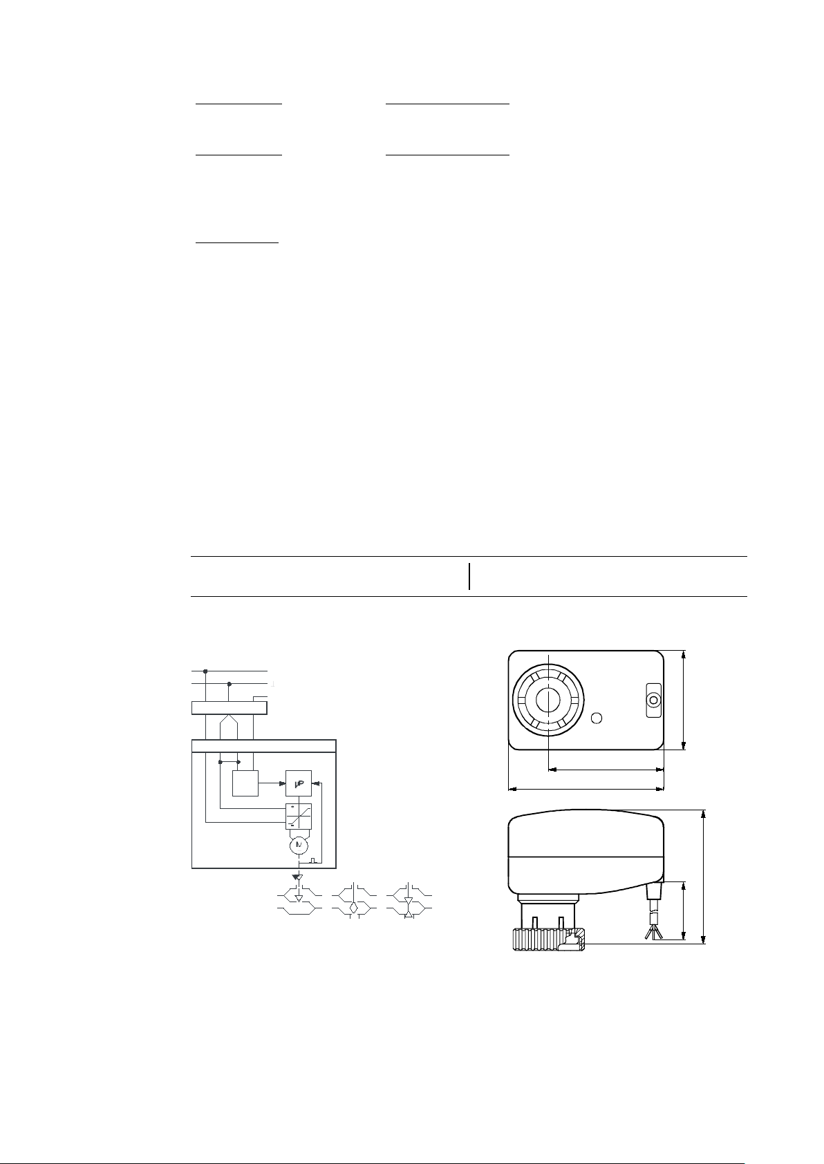
Wiring diagram
A06147
Control current
max. 0,5 mA
Dimension drawing
M06146
Max. operating temperature
100 °C at valve
Fitting instructions
MV 505456
Accessories
0371235 001
Adaptor for fitting to Oventrop valves (M30 × 1)
0550393 001
Adaptor Danfoss RA2000, 22 mm
0371356 001
Adaptor for fitting to Beulco or Tobler underfloor-heating distribution stations (M30 × 1)
0550393 002
Adaptor Danfoss RAVL, 26 mm
0550393 003
Adaptor Danfoss RAV, 34 mm
0371361 001
Adaptor for fitting to Herz valves, type Herz-TS’90 (M28 × 1,5)
0371363 001
Adaptor for fitting to Tour & Andersson valves, type TA/RVT (M28 × 1,5)
1)
Direction of operation 2: rising 0…10V = drive extends (VXL, VUL, BUL closes, BXL control passage opens).
2)
Pushing force: min. 100 N, max. 150 N
3)
The direction of operation and the setting of the control voltage can be set using jumpers
7155011003 07
AXM 117S: Motorised drive (with positioner) for unit valves
How energy efficiency is improved
Automatic valve adjustment and intelligent cut-out enable maximum energy efficiency.
Areas of application
Actuation of through and three-way unit valves in the VUL, BUL, VXL and BXL series. For controllers
with continuous output in combination with intelligent unitary control systems.
Features
• Pushing force 120 N
• Fits onto valve with M30 × 1.5 thread
• Stepping motor with control and electronic cut-off
• Version with control action A or B or adjustable
• Maintenance-free gearbox
• Suitable for retrofitting existing installations using an appropriate adaptor
• Operating status control using integrated LED display
Technical description
• Two-part plastic housing, light grey (RAL7035)
• Nickel-plated brass nut
• Connecting cable, light grey 1.50 m long, 3 × 0.25 mm²
• Running time for 4 mm stroke: 60 s
• Installation position: vertical to horizontal, but not upside down
Direction of operation 1: rising 0…10V = drive retracts (VXL, VUL, BUL opens, BXL control passage closes).
Operation
During commissioning (with valve fitted), the actuator moves to the two end positions and memorises
the number of steps taken to do so. The 0...10 V control signal is then linearly assigned to this effective stroke. The motor activates the valve and switches off as soon as the stroke position concurs with
the controller signal. In the end positions or in the event of an overload, the motor is switched off within 2 minutes. If the control voltage has not changed for 2 hours (in the range 0...0,5 V), the motor –
after approx. 2 hours – runs briefly to the end positions and, if necessary, corrects its position
memory. A complete cycle is performed every 24 hours on the AXM117SF202 and F302 in order to
prevent the plug from jamming. The LED lights up when power is applied to the drive, and flashes
when the motor is running.
Sauter Components
55.011 AXM 117S
Stroke
max. 4,5 mm
Running time
15 s/mm
7155011003 07
74
55
47
L=1,5m
62,5
M06146a
B10 094a
24 V~
VUL / VXL
2
1a 1 b
3
21 3
0...10V
A/D
BXL
BUL
1b
blau
bleu
blue
azzu ro
azul
bl å
blauw
2
rot
rouge
red
ross o
rojo
röd
rood
1a
sc hw arz
noir
black
n ero
negro
svart
zwa rt
3
weiss
blanc
white
bianco
blanco
vit
w it
AXM117SF202 or AXM117SF402, direction of operation 1
As the control signal rises, the drive spindle retracts and the VUL, VXL through valves and the BUL
three-way valve (control passage) open. On the BXL three-way valve, the control passage closes.
AXM117SF302 or AXM117SF402, direction of operation 2
As the control signal rises, the drive spindle extends and the VUL, VXL through valves and the BUL
three-way valve (control passage) close. On the BXL three-way valve, the control passage opens.
The black earth lead 1a (24 V~) and the blue earth lead 1b (control voltage) should be connected
together to a common earth lead.
AXM117SF402
After removing the cap on the lid, you can make the following settings using jumpers:-
– Auto reset ‘on’ or ‘off’. In the ‘on’ (active) position, the drive re-adjusts itself every 24 hours by
moving to the end position or to the internal stop. In the ‘off’ (inactive) position, this readjustment does not occur.
– The input signal can be set to either 0...10 V or 5,2...10 V or 0...4,8 V.
– Direction of operation 1 or 2 can be selected; factory setting is direction of operation 2.
Replace the cap after you have finished making the setting.
Engineering and fitting notes
No tools should be used to fit the drive onto the valve. In the event of a power failure, the valve can be
opened by removing the drive. When connecting or transposing the power cable, power must be
switched off.
The drive must only be fitted on the valve when the drive spindle is notextended 100%. Status when
delivered: 50% of stroke.
Fitting outdoors. If the devices are fitted outdoors, we recommend that additional measures be taken
to protect them against the effects of the weather.
Standards and regulations
The drive conforms to the relevant EU standards.
EMC Directive: CE as per EN 61000-6-3 and EN 61000-6-1
Additional technical details
Wiring diagram Dimension drawing
Sauter Components
 Loading...