

sauter AVM Series,AVM 104S F132,AVM 105S F132,AVM 114S F132,AVM 115S F132 Instructions Manual
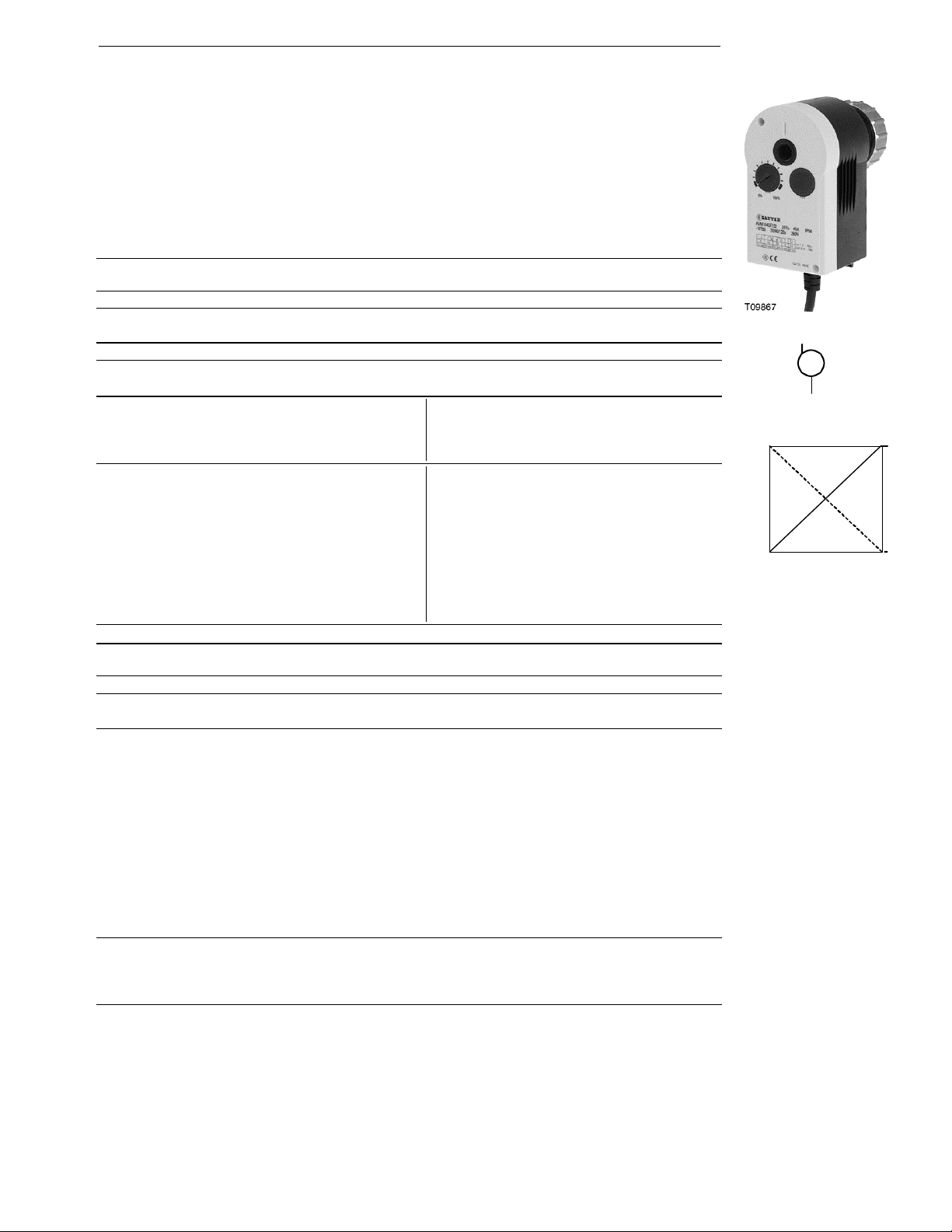
AVM 104S…115S: Valve drive with Sauter Universal Technology SUT
For controllers with continuous output (0...10V) or switched output (2- or 3-point control). To operate
through valves or three-way valves in series VXN/BXN, VUD/BUD, VUE/BUE. Choice of characteristic
(linear/equal-percentage) can be set on the actuator.
Two-part housing of fire-retardant plastic, lower part in black, upper part in yellow. With stepping motor,
SUT electronic control unit and maintenance-free gears. Fixing bracket of plastic and cap nut of brass
for fitting the valve. Assembly with the valve is practically automatic. Direction of operation can be
changed at the cable. Electronic, torque-based cut-out via stops on either the actuator or the valve;
automatic adaptation to the valve’s stroke. Coding switches for selecting characteristic and running
time. Disengageable gears for positioning the valve by hand (Allen key enclosed with product). Power
cable 1,2 m long, 5× 0,5 mm². Fitting position: anywhere from vertical to horizontal, but not upside dow n.
mm
Stroke
mm
5)
Pushing force
Pushing force
3)
; MV 505795
3)
Power Weight
N
2)
2)
0
0 or 10V
Switching range Xsh 200 mV
1)
200 ms
Wiring diagram A09673
Power Weight
N
; MV 505795
kg
0,7
0,7
kg
Type Running timesStroke
For valves with linear characteristic, can be switched over to equal-percentage
AVM 104S F132
AVM 114S F132
35/65/130 7,5 250 24 V~/=
60/120 7,5 500 24 V~/=
For valves with equal-percentage characteristic, can be switched over to linear
AVM 105S F132
AVM 115S F132
Positioner
Control signal 0...10V, Ri > 100 kΩ Starting point U
Positional feedback signal 0...10V, load > 10 kΩ Control span ΔU 10V
Power supply 24V∼± 20%, 50...60 Hz Protection (horizontal) IP 54 as per EN 60529
Power consumption
AVM 105S F132 4,8 W 8,5 VA Response time
AVM 115S F132 4,9 W 8,7 VA
Max. m e d i a t e m p e r a t u r e 100 °C Dimension drawing M09743
Permissible amb. temp. –10...55 °C Fitting instructions 1 . 4S MV 505790
Ambient humidity 5…95 %rh Fitting instructions 1 . 5S MV 506065
1)
35/60/120 8,0 250 24 V~/= 0,7
60/120 8,0 500 24 V~/= 0,7
24V= 2)+ 20% / - 10% Protection class III as per IEC 60730
without condensation Declaration on materials MD 51.362
For control valve type KTM512 / TA-Regulator DN 15…50
Type Running time
s
AVM 115S F901
80/160 10,0 500 24 V~ 0,7
Deviation from standard type: inverse scale therefore inverse direction of operation. Adaptor for
control valve available on the valve or from TA-Regulator, stating reference no. 52 757 003.
Accessories
0313529 001* Split-range unit for setting sequences; to be fitted in separate distribution box as
per MV 505671
0372145 001* Single auxiliary change-over contacts
0372145 002* Double auxiliary change-over contacts
0372249 001* Intermediate piece required for media temperature >100 °C
(recommended for temperature < 10 °C); MV 505932
0372273 001* Adaptor for Siemens VVG / VXG 44 and 48 valves; MV 505848
0372286 001 Potentiometer
0372286 002 Potentiometer
0372286 003 Potentiometer
0372462 001 CASE Drives PC Tool for configuration of actuators per computer; MV 506101
*) Dimension drawing or wiring diagram are available under the same number
1) Also for 2-point or 3-point. depending on type of connection
2) 24V = for input signal of 0...10V only on AVM 1 . 4; on AVM 1 . 5S for all functions.
3) Fully variable from 0...100%; max. loading 5 (2) A. 24....230V
4) Only one potentiometer or one set of auxiliary contacts can be fitted to each drive!
5) Maximum stroke of drive = 10,0 mm
4)
130 Ω; MV 505795
4)
1000 Ω; MV 505795
4)
5000 Ω; MV 505795
51.362/1
M
Y07552
100 %
D
ir
of
ecti
o
pe
on
r
a
tio
n
2
o
0 %
0 V Output signal y 10 V
ion
1
ct
n
tio
Dire
a
er
p
f o
B07650
Sauter Components
7151362003 03

51.362/2 AVM 104S...115S
Operation
Depending on how it is connected (see wiring diagram). the actuator can be used as a continuous
0...10V. as a 2-point (open/close) or as a 3-point drive (open/stop/close) with intermediate position.
The running time can be matched to requirements using switches S1 and S2 (AVM 105, S1 only). The
characteristic (equal-percentage or linear) can be selected with switch S3. The AVM 104/114 is combined with valves that have a linear basic characteristic such as the VXN and BXN valves. The
AVM 105/115 is combined with valves that have an equal-percentage basic characteristic such as the
VUD. BUD. VUE and BUE valves. The AVM 115 can be fitted on a valve with a linear characteristic (e.g.
VUE 050F200). but you must pay attention to the position of the coding switches. With the AVM 105. it is
not possible to create an equal-percentage characteristic for a valve with a linear characteristic.
Manual adjustment is performed by disengaging the gears (sliding switch next to the power cable) and
simultaneously turning. using an Allen key in the insert on the upper part of the drive. Eight mm of
stroke is attained with 1½ turns.
N.B.: After manual adjustment. re-set the sliding switch (engage the gears).
Connected as a 2-point actuator
Open/close activation can be effected via two wires. Power is applied to the drive via the blue and the
brown wires. On connecting power to the black wire. the valve’s control passage opens. When power
is switched off. the drive goes to the opposite end position and closes the valve.
The unused red and grey wires should not be connected. nor should they come into contact with other
wires. We recommend that you insulate them.
Connected as a 3-point control unit
By connecting power to the wires (brown or black). the valve can be moved to any position. The coupling rod extends and opens the valve if power is applied to the black wire. It retracts and closes the
valve if power is applied to the blue and the brown wires.
In the end positions (on hitting a stop in the valve or reaching the maximum stroke) or in the event of
an overload. the electronic motor cut-off responds (no end switches). The direction of the stroke can be
changed by swapping the power-supply w ires over (BN/BK). The unused red and grey w ires should not
be connected. nor should they come into contact with other wires. We recommend that you insulate
them.
Connections for control voltage 0...10V
The integrated positioner controls the drive as a function of the controller’s positioning signal y.
Direction of operation 1 (mains power on brown wire): the coupling rod extends and opens the valve
(control passage) as the positioning signal rises.
Direction of operation 2 (mains power on black wire): the coupling rod retracts and closes the valve
(control passage) as the positioning signal rises.
The starting point and the control span are both permanently set. There is a split-range unit available
(as an accessory) for setting partial ranges.
After manual adjustment or in the event of a power failure for longer than 5 minutes, the drive readjusts itself automatically, always with a running time of:
AVM 104 65 s
AVM 114 60 s
AVM 105 35 s
AVM 115 60 s
After power has been applied. the stepping motor moves to the lower stop. connects to the valve spindle and moves to the upper stop in the valve. thereby determining the closed position. Depending on
the control voltage. any stroke between 0 and 8 mm can then be obtained. Thanks to the electronics
unit. no steps can be lost. and the drive needs no periodical re-adjustment. Parallel operation of more
than one drive of the same type is guaranteed.
The feedback signal y0 = 0...10V corresponds to the effective stroke of 0 to 8 mm.
If the control signal (0...10V) is interrupted and direction of operation 1 is connected. the valve closes
fully (0% position).
The valve’s characteristic can be selected using the coding switch. The characteristics can be generated only if the drive is used as a continuous drive. Other switches enable the running times to be set.
These can be applied irrespective of whether the 2-point. 3-point or the continuous function has been
chosen.
Sauter Components
7151362003 03
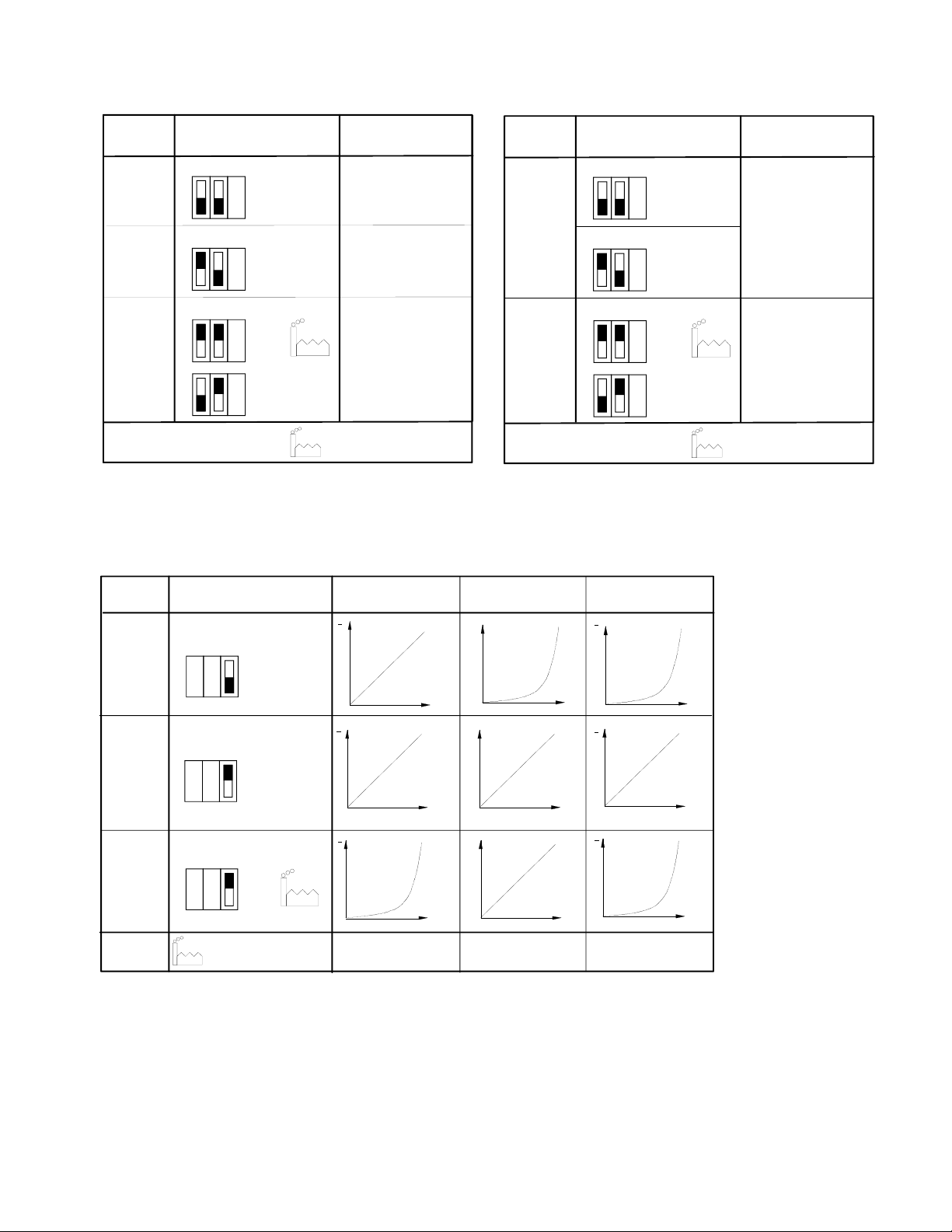
Coding switch for running time selection
AVM 104 S
Run time
per mm
4,375 s
8,125 s
Switch coding
1 2 3
On
Off
1 2 3
On
Off
Run time for
8 mm stroke
35 s ± 1
65 s ± 2
AVM 114S
Run time
per mm
7,5 s
Switch coding
1 2 3
1 2 3
AVM 104S...115S 51.362/3
Run time for
8 mm stroke
On
Off
60 s ± 2
On
Off
1 2 3
On
Off
16,25 s
On
Off
= factory setting
Coding switch for characteristics selection
AVM 104S , AVM 114S
Desired
character.
curve
Switch coding
Characteristic
curve for valve
v
1 2 3
On
Equal
percentage
Off
v
1 2 3
Linear
On
Off
v
1 2 3
On
Off
Equal
percentage
= factory setting
130 s ± 4
Stroke
Stroke
Stroke
B10699
Stroke
Stroke
Stroke
15 s
Characteristic
curve for drive
Signal
Signal
Signal
1 2 3
On
Off
On
Off
Effective on valve
v
= %
Signal
v
lin
Signal
v
= %
Signal
B10701
120 s ± 4
= factory setting
B10700
Sauter Components
7151362003 03
 Loading...