

Page 1

Page 2
INSTRUCTIONS FOR USE, INSTALLATION AND SERVICING
FOR ISOFAST CONDENS F 35 E
3
4000135500-2 04/04
INSTRUCTIONS FOR USE
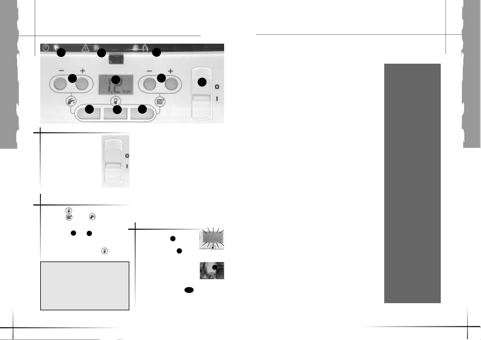
Lighting : make sure that:
• the boiler is connected
to the electrical supply,
• the gas service tap is open,
• Switch ON (I).
Switch off the boiler : Switch
to OFF (0) : the electrical
supply is off. Stop the gas
supply if the boiler is to be
out of use for a long time.
In case of fault, the
red warning light will flash
and a code appears
on the boiler display .
Code 21: Water pressure too
low: open the blue tap (t)
situated under the boiler until a
pressure of 1.5 bar is obtained.
Other codes: press the key of the
room thermostat and read the indications
given by the display.
Lighting/switch off the boiler
Fault indication
1-On/Off switch.
2-Room thermostat disabled when the
button light is ON
3-Sanitary function enabled when the
button light is ON
4-Heating function enabled when the
button light is ON
5-Hot water temperature adjuster.
6-Heating temperature adjuster.
7-Graphic display.
8-Green running light.
9-Red, flashing fault light.
10- Yellow running lamp for the burner.
1
➡
4
2
3
5
6
7
8
9
10
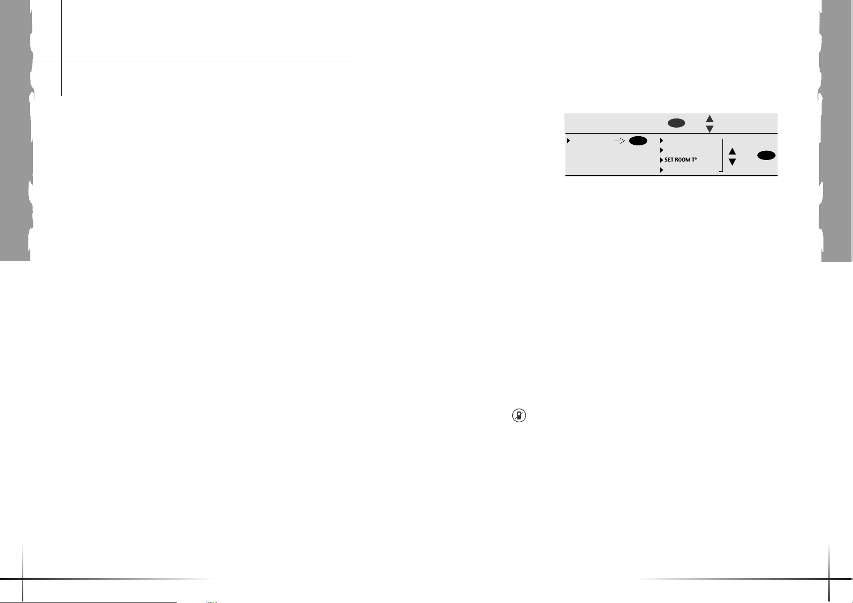
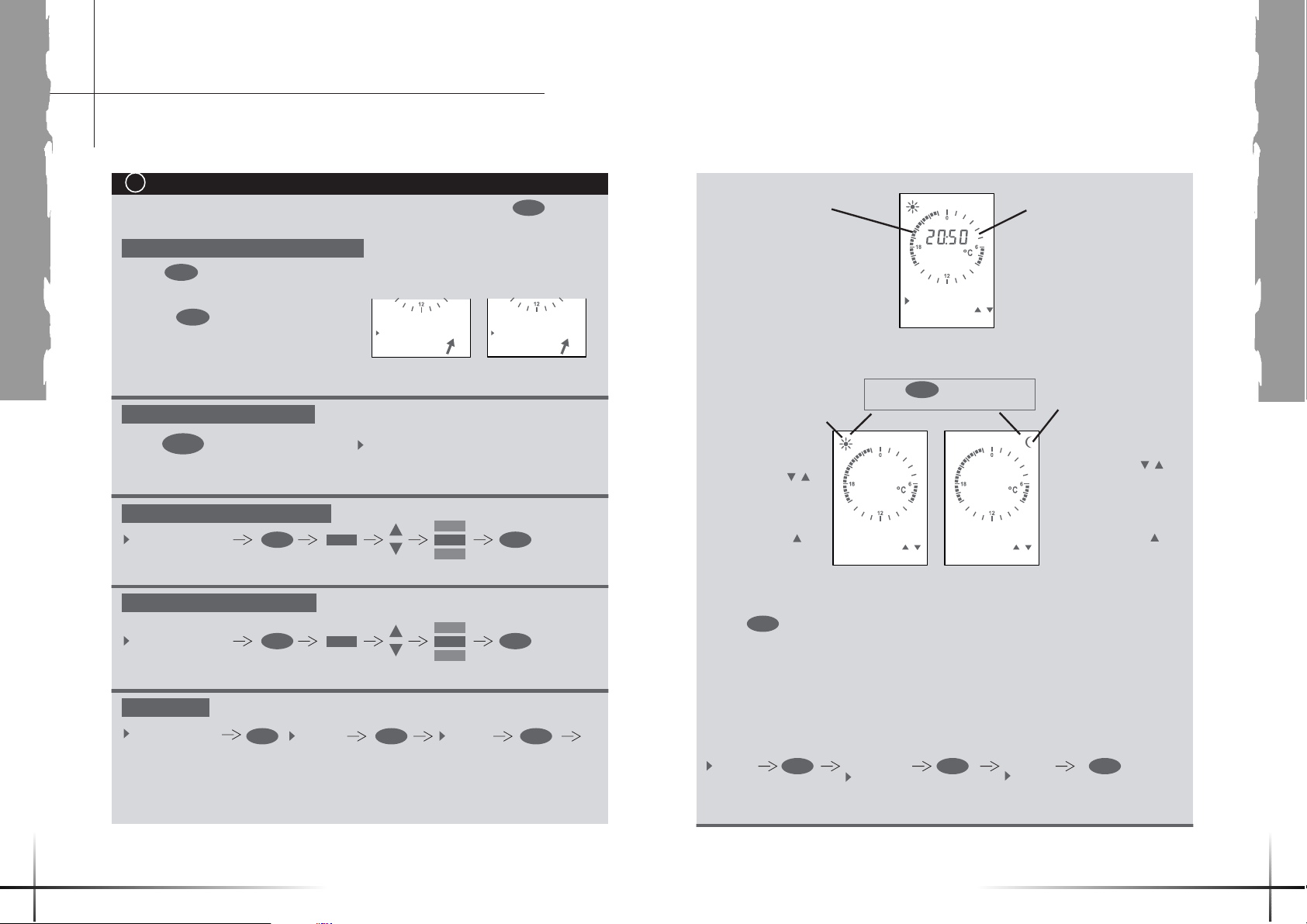
Operation without room thermostat
• Press the key (the key will light-up)
• Press the and/or buttons to
activate the heating and/or hot water
functions
• Use buttons and to determine the
heating and hot water temperatures.
• To revert to the operating mode with room
thermostat, again press the key (the
light will turn OFF;
5
6
9
7
t
21
OK
2
Important notice : The settings performed
on the boiler control panel are not
transmitted to the room thermostat.
Perform the temperature settings from
the wireless room thermostat supplied
together with the boiler, strictly adhering
to the instructions given in this manual,
pages 10 through 17.
Contents
INSTRUCTION FOR USE
Controls and Lighting page 2
Important informations 3 - 5
Guarantee informations 6 - 7
Controls informations 8 - 17
INSTALLATION
INSTRUCTIONS
General informations 18
Dimensions 19
Technical Data 20 - 23
Boiler coponents 24
Schematic layout of boiler 25
Boiler location 26 - 27
Flue location and
Ventilation 28 - 31
Heating System 32 - 33
Domestic
Hot Water System 33
Boiler Installation 34
Piping installation 35 - 38
Electrical Connection 39
Commissioning
on boiler 40 - 43
Commissioning
on room thermostat 44 - 51
Gas conversion 52 - 53
SERVICING
INSTRUCTION
Routine Cleaning
and Inspection 54 - 59
Wiring Diagram 60 - 61
Fault Finding 61 - 63
Replacement of Parts 64 - 72
Spare Parts 73
Important information
The instructions consist of
three parts, User,
Installation and Servicing
Instructions, which
includes the Guarantee
Registration Card. The
instructions are an integral
part of the appliance and
must, to comply with the
current issue of the Gas
Safety (Installation and Use)
Regulations, be handed
to the user on completion
of the installation.
General
This combination boiler is
able to provide room heating
as part of a central heating
system, and domestic hot
water direct from the cold
water supply without the
need for secondary storage.
The central heating water
temperature and domestic
hot water temperature can
both be adjusted on the
boiler.
Once the controls are set
the boiler operates
automatically.
A frost protection program is
also included.
Please read these
instructions and follow them
carefully for the safe and
economical use of your
boiler.
Gas Category
This boiler is for use only on
Natural gas (G20) or
propane (G31).
Gas Safety (Installation
and Use) Regulations
In your own interests and
that of safety, it is the Law
that ALL gas appliances are
installed by a competent
person in accordance with
the current issue of the
above regulations.
Gas Testing and
Certification
The boiler is tested and
certificated for safety and
performance.
It is, therefore, important
that no alteration is made to
the boiler unless approved,
in writing, by Saunier Duval.
Any alteration not approved
by Saunier Duval, could
invalidate the certification,
boiler warranty and may also
infringe the current issue of
the statutory requirements.
CE Mark
This boiler meets the
requirements of Statutory
Instrument, No. 3083 The
Boiler (Efficiency) Regulations,
and therefore is deemed to
meet the requirements of
Directive 92/42/EEC on the
efficiency requirements for
new hot water boilers fired
with liquid or gaseous fuels.
Type test for purposes of
Regulation 5 certified by :
Notified body 0086.
Product/production certified
by : Notified body 0086.
Page 3
USERS
54
Important information
The CE mark on this
appliance shows
compliance with :
1. Directive 90/396/EEC on
the approximation of the
laws of the Member States
relating to appliances
burning gaseous fuels.
2. Directive 73/23/EEC on
the harmonisation of the
Laws of the Member States
relating to electrical
equipment designed for use
within certain voltage limits.
3. Directive 89/336/EEC on
the approximation of the
Laws of the Member States
relating to electromagnetic
compatibility.
Control of Substances
Hazardous to Health
Under Section 6 of The
Health and Safety at Work
Act 1974, we are required
to provide information on
substances hazardous to
health.
The adhesives and sealants
used in this appliance are
cured and give no known
hazard in this state.
Insulation Pads
These can cause irritation to
skin, eyes and the
respiratory tract.
If you have a history of skin
complaint you may be
susceptible to irritation. High
dust levels are usual only if
the material is broken.
Normal handling should not
cause discomfort, but follow
normal good hygiene and
wash your hands before
eating, drinking or going to
the lavatory.
If you do suffer irritation to
the eyes or severe irritation
to the skin seek medical
attention.
Spare Parts
REMEMBER, When
replacing a part on this
appliance, use only spare
parts that you can be
assured conform to the
safety and performance
specification that we require.
Do not use reconditioned or
copy parts that have not
been clearly authorised
by Saunier Duval.
Manual Handling
Guidance
During the appliance
installation and the
replacement of the
heat exchanger it will be
necessary to employ caution
and assistance whilst lifting
as the appliance or
component exceeds the
recommended weight for a
one man lift.
In certain situations it may
be required to use a
mechanical handling aid.
Take care to avoid trip
hazards, slippery or wet
surfaces.
Gas Leak or Fault
If a gas leak or fault exists or
is suspected, turn the boiler
mains electrical supply off
and turn off the gas supply
at the meter. Consult your
local gas company or your
local installation/ servicing
company.
Electrical Supply Failure
The boiler must be earthed.
The boiler will not work
without an electrical supply.
Normal operation of the
boiler should resume when
the electrical supply is
restored.
Reset any external controls,
to resume normal operation
of the central heating.
If the boiler does not resume
normal operation turn the
mains reset switch off and
on. If the boiler does not
resume normal operation
after this the overheat stat
may have operated. The
overheat stat would only
operate under abnormal
conditions and, under these
circumstances; it would be
advisable to consult your
installation / servicing
company.
Boilers Installed in a
Compartment or Cupboard
If the boiler is fitted into a
compartment or cupboard,
it does not require any
ventilation openings. Do not
use the compartment
or cupboard for storage.
Pluming from flue terminal
Like all condensing boilers
this appliance will produce a
plume of condensation from
the flue terminal in cool
weather. This is due to the
high efficiency and hence
low flue gas temperature of
the boiler. It is normal and
not a fault indication.
Replacement Parts
If replacement parts are
required contact
Saunier Duval service using
the telephone number on
the back cover of this
booklet.
Please quote the name of the
appliance this infomation will
be on the front of the
appliance.
Protection Against Freezing
The room thermostat
automatically ensures a
minimum installation
temperature of 6°C.
This protection is ensured
by the room thermostat as
long as it is active. This
means that the button
of the boiler must not be lit
and that the batteries of the
room thermostat must be in
good condition.
If you are out of home for a
few days, use the holidays
mode of your room
thermostat, and set the Start
and End dates, as well as
the desired temperature.
If the mains electricity and
gas are to be turned off for
any long periods during
severe weather, it is
recommended that the
whole system, including the
boiler, should be drained to
avoid the risk of freezing.
Contact your
installation/servicing
company as draining, refilling
and pressurising MUST be
carried out by a competent
person.
As a safety feature the boiler
will stop working if the
condensate drain becomes
blocked. During freezing
conditions this may be
due to the forming of ice in
the condense drain external
to the house. Release an ice
blockage by the use of
warm cloths on the pipe.
The boiler should then
restart. Contact your
installation/servicing
company if the fault
persists.
Draining and Filling
This boiler works in a
pressurised system, which
must only be drained,
refilled and pressurised by a
competent person.
Pressure Relief Safety
Valve
A pressure relief safety valve
and discharge pipe is fitted
to the boiler. This valve must
not be touched. Should
there be any discharge from
the pipe, isolate the boiler
electrical supply and
call your installer or
Saunier Duval service using
the telephone number on
the back cover of this
booklet.
Access to the user menu :
+
HOLIDAYS START DATE
OK
MENU
END DATE
CANCEL
OK
+
Page 4

To ensure the continued
efficient and safe operation
of the appliance it is
recommended that it is
checked and serviced as
necessary at regular
intervals. The frequency of
servicing will depend upon
the particular installation
conditions and usage, but in
general once a year should
be enough. Refer to Section
«Routine Cleaning and
Inspection».
If this appliance is installed
in a rented property there is
a duty of care imposed on
the owner of the property by
the current issue of the Gas
Safety (Installation and Use)
Regulations, section 35.
Servicing/maintenance
should be carried out by a
competent person in
accordance with the rules in
force in the countries of
destination.
To obtain service,
please call your installer or
Saunier Duval service using
the telephone number on
the back cover of this
booklet.
Please be advised that the
‘Benchmark’ logbook
should be completed by the
installation engineer on
completion of
commissioning and
servicing.
All CORGI Registered
Installers carry a CORGI ID
card, and have a registration
number. Both should be
recorded in your boiler
Logbook. You can check
your installer is CORGI
registered by calling CORGI
direct on: 01256 372300.
Cleaning
The boiler casing can be
cleaned with a damp cloth
followed by a dry cloth to
polish.
Do not use abrasive or
solvent cleaners.
Boiler casing
CAUTION. Do not remove
or adjust the casing in any
way, as incorrect fitting may
result in faulty operation. If in
doubt, consult your
installation/service company.
USERS
76
Servicing,
all you need to know
Many thanks for choising
Saunier Duval market
leaders in boiler
manufacture,
Your appliance is
guaranteed for a period of
24 months from the date
of installation or 30
months from the date of
manufacture whichever is
the shorter and covers
manufacturing defects only.
We, Saunier Duval,
undertake to repair or
replace parts free of charge
which are recognised by us
to be of faulty manufacture if necessary after return to
our factory for examination on condition that :
a) The appliance was
installed by a qualifled gas
installer in accordance with
installation instructions, and
all the relevant codes of
practice, standards and
legislation in force.
b) The appliance has been
used for normal domestic
purposes and in accordance
with the manufacturer's
operating and maintenance
instructions.
c) The appliance has not
been serviced, maintained,
repaired dismantled or
tampered with during the
guarantee period, by anyone
other than an engineer
approved by Saunier Duval.
d) The appliance is still in
the possession of the
original user, and proof of
purchase in the form of a
receipt or invoice is shown
to the service engineer on
request.
The repair or replacement of
parts during the guarantee
period does not have the
effect of extending the
period.
This guarantee does not
cover :
a) Any defects or damage
resulting from incorrect or
poor installation, inadequate
servicing, or maladjustment
of the gas or water used.
b) Any defects in the system
to which the appliance is
connected.
c) Any deterioration or
maladjustment following
changes in the nature or
pressure of the gas or the
water used, or a change in
the characteristics of the
electrical supply voltage.
Notification of any fault
should be made to the
appliance installer.
No repairs should be
undertaken upon the
Welcome users
appliance, intending it to be
covered by the product
guarantee without prior
authorisation from
Saunier Duval.
IMPORTANT : The
appliance serial number
must be quoted on all
correspondence/contact
made with Saunier Duval.
This guarantee is in
addition to your statutory
and other legal rights, which
will not be excluded or
diminished by the return
of the guarantee registration
card.
Page 5
USERS
8 9
SYSTEM PRESSURE
TOO LOW
FILL IN AT 1,5 BAR
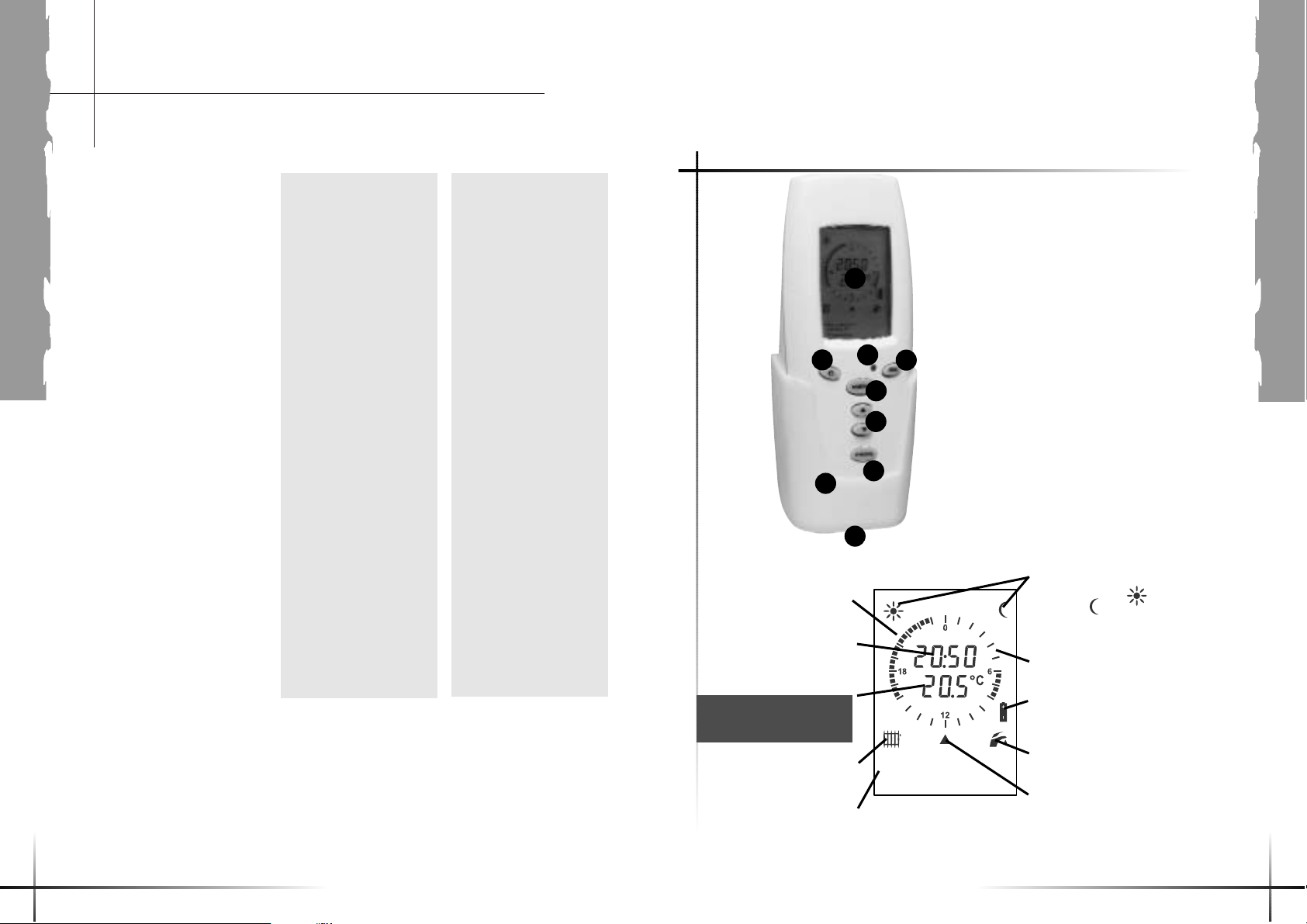
Ambient
temperature display
Time period for the
COMFORT temperature
Hot water
mode indicator
Heating mode
indicator
Time display
Time period for the
ECO temperature
Low battery
indicator
1-Display.
2- Fault indicator.
3-Return to previous menu
4-Confirm OK.
5-Access to the menus.
6 - Menu scrolling
7-Changing the mode
8-Wall bracket
9-Mains power plug
1
2
3
4
5
6
7
8
9
Fault description
Heating demand
indicator
Indicators of the
current temperature levels
for “COMFORT
or ECO”
(Day/Night).
(Attention: this value may
vary when you hold the
thermostat in your hand).
Your Isofast boiler is
factory set to operate within
a customary installation.
Nevertheless, as many
installations may
incorporate specific
features, feel free to contact
your installer who will be
able – by adapting the
parameters of the boiler
(maximum temperature
and/or maximum power of
the heating system) - to
warrant you the best
operating performance of
your installation.
These settings being made,
you still have the possibility
of selecting the ambient
temperature to suit your
own requirements not only
when you are at home, but
also during nightime or
when you are out
All these settings are
achieved from the room
thermostat supplied
together with your boiler: if
you accurately determine
the temperatures that best
suit to your needs, you will
make significant savings in
terms of gas consumption.
Control
as a source of savings
Essential adjustments to
the wireless room
thermostat :
A – Setting the time
B – Setting the date
The thermostat’s
weekly programme
functions enable you :
C – To activate or
deactivate the heating
function.
D – To have a standard
weekly programme by
activating the programme
pre-set at the factory.
E – To bypass the current
programme, temporarily,
to increase or lower the
temperature at any time
during the day.
F – To set up a custom
programme for each day of
the week, with 2
temperature levels, for
example:
• COMFORT for the periods
you are present and.
• ECO at night or when you
are away.
G – To have the same
temperature 24 hours a day
by deactivating the
programme.
H – To leave on holiday,
determining the desired
temperature according to the
date you leave and when
you return.
I – To select the temperature
of your domestic hot water
from 38°C to 60°C.
However, keeping the
temperature below 50°C,
reduces gas consumption
and provides good
protection against scalds.
J – To prevent undesired
alterations to your settings
by locking the thermostat’s
buttons.
K – To be informed of any
operating faults in the
boiler and be instructed in
the procedure to follow.
Page 6
USERS
1110
Control
as a source of savings
A B
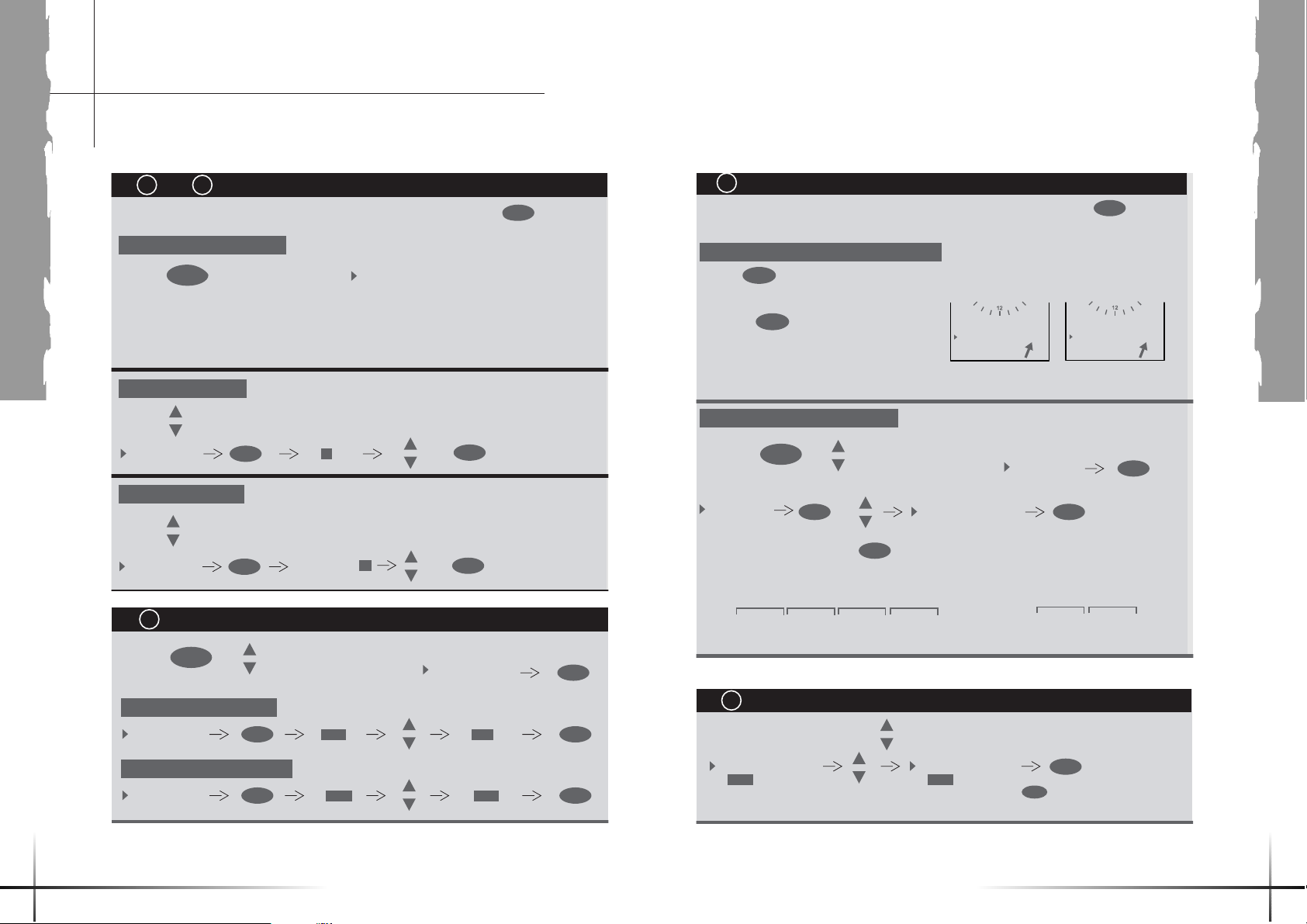
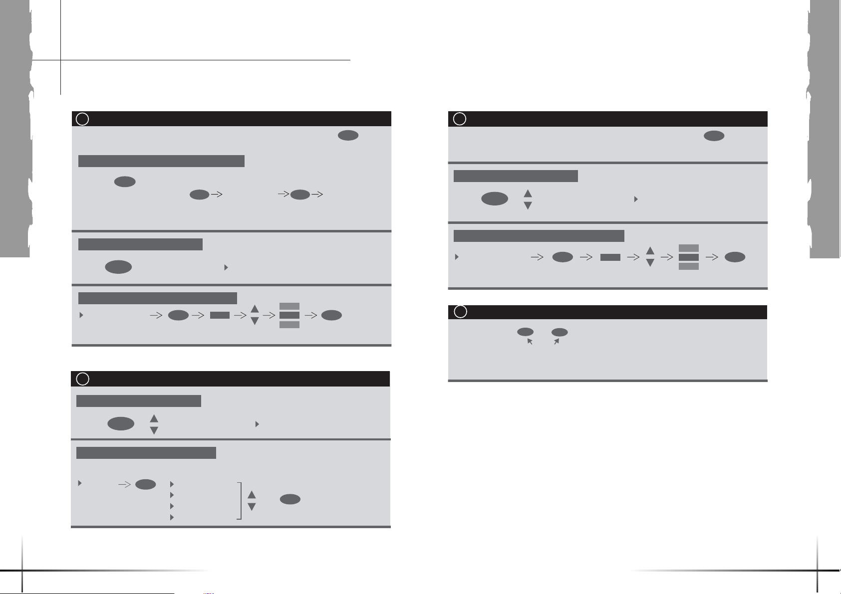
Progress of the operations :
at any time takes you back to the previous step
1 - Accessing the user menu
• Press to call up the next menu:
2 - Setting the time
• Use the buttons to select the "Set time" menu:
3 - Setting the date
• Use the buttons to select the "Set date" menu:
• Press to select the "ON/OFF heating "
menu:
1 - Activate the heating
MENU
SET TIME
SET DATE
C
MENU
ON/OFF HEATING
Settings for the time and the dateand
OK
OK
Please note that pressing button
SET COMFORT T¡
SET ECO T¡
PROGRAMME
SET HOT WATER T¡
ON/OFF HEATING
HOLIDAYS
SET TIME
SET DATE
17:23
TUE 14/JUA/ 03
+
+
OK
OK
Activating/deactivating the heating function
PROGRAMME
+
OK OK
OFF
SET HOT WATER T¡
ON/OFF HEATING
...
ON
C
OK
D
Progress of the operations:
1 - Activating the weekly programme
PROG
• Press , the room thermostat shows this display:
• Pressing reverses
ON and OFF mode every time
• When the ON mode appears, wait 5 seconds for the display to return to normal position
and automatically validate the selection.
2 -Accessing the initial programme
• Press to select the
"Programme" menu :
PROGRAMME
• Exit from the menu by pressing , which initiates the standard weekly programme
pre-set at the factory :
Monday to Friday
• Pressing one of the scroll buttons calls up the menu for setting the ambient temperature :
PROG
MENU
ECO ECOCOMFORT COMFORT
11 PM >> 6 AM>> 8 AM >> 4 PM >> 11 PM
E
Temporarily bypassing the weekly programme
Activating the initial programme
Please note that pressing button
at any time takes you back to the previous step.
or
PROGRAMME ON
OK
+
OK
+
PROGRAMME OFF
INITIAL PROGRAMME
MONDAY
SET COMFORT T¡
SET ECO T¡
PROGRAMME
...
C
Weekends
ECO temperature 16°C COMFORT temperature 19°C
ECO COMFORT
11 PM >> 7 AM >> 11 PM
C
OK
2 - Deactivate the heating
ON/OFF HEATING
OK OK
ON
OFF
SET ROOM T¡
22¡C
This setting is automatically cancelled when the programme changes to Eco or Confort temperature level.
SET ROOM T¡
20¡C
Confirm by pressing
OK
OK
Page 7
USERS
1312
PROG
OK
MODIFY
COPY TO
MONDAY
TUESDAY
MONDAY
TUESDAY
OK OK OK
• Press to confirm the parameters you have set for the day.
• Follow the same procedure for every day of the week or use the duplication function,
as explained below.
19.5
MODIFY
TIME-SLOTS :
T¡ CHOICE : PROG
19.5 16.5
Press to switch from
COMFORT to ECO temperature
This symbol indicates the
mode authorising deletion
of black squares to set up
operating periods at the
stated ECO temperature
using the buttons / .
E.g. :
In the case of the
illustration opposite, each
press of the button
adds a blank from 6 AM
onwards, corresponding to
an extra 30 minutes
heating at 16.5°C.
E.g. :
In the case of the
illustration opposite, each
press of the button
adds a square from 11
PM onwards,
corresponding to an extra
30 minutes heating at
19.5°C.
This symbol indicates the
mode authorising additional
operating periods at the
stated COMFORT
temperature (black
squares)
using the buttons / .
The squares indicate
the time periods when the boiler will
provide the COMFORT temperature
level
(e.g.: 19.5°C between 4 PM and 11
PM and 6 AM and 8 AM)
The blanks indicate
the time periods when the boiler will
provide the ECO temperature level.
(e.g.: 16.5°C between 8 AM and 4
PM and 11 PM and 6 AM)
Duplicating a programme
• To save time, you can copy the parameters you have set onto another day via the menu :
/
MODIFY
TIME-SLOTS :
T¡ CHOICE : PROG
/
MODIFY
TIME-SLOTS :
T¡ CHOICE : PROG
/
23:00 6:00
Control
as a source of savings
OK OK
SET COMFORT T¡
SET COMFORT T¡
SET ECO T¡
PROGRAMME
...
19.0¡C
19.5¡C
18.5¡C
20.0¡C
OK
PROGRAMME
MODIFY
COPY TO
MONDAY
TUESDAY
WEDNESDAY
THURSDAY
FRIDAY
SATURDAY
SUNDAY
INITIAL PROGRAMME
OK OK
/...
/...
(to set the desired temperature during the day)
(to set the desired temperature
during the night or while you are away)
OK OK
SET ECO T¡
16.0¡C
16.5¡C
16.0¡C
17.0¡C
/...
/...
(to allocate time periods for the
Comfort and Eco temperatures)
PROG
PROG
• When the ON mode appears, wait 5 seconds for the display to return to normal position
and automatically validate the selection.
PROGRAMME OFF
PROGRAMME ON
or
C
• Press to call up the next menu:
• Press , the room thermostat shows this display:
• Pressing
reverses ON and OFF mode every time.
Progress of the operations :
MENU
Setting the custom weekly programme
1 - Activating the weekly programme
2 - Access to the user menu
3 - Setting the Comfort temperature
4 - Setting the Eco temperature
5 - Programme
Please note that pressing button
at any time takes you back to the previous step.
F
Page 8
USERS
1514
SET ECO T¡
PROGRAMME
SET HOT WATER T¡
...
OK OK
SET HOT WATER T¡
50¡C
51¡C
49¡C
52¡C
/....
/....
(to set the hot water to
the desired temperature)
C
• Press to call up the next menu :
Progress of the operations :
MENU
Setting the hot water temperature
1 - Access to the user menu
2 - Setting the hot water temperature
Please note that pressing button
at any time takes you back to the previous step.
+
I
Locking/unlocking the thermostat’s buttons
J
• Holding down the and buttons simultaneously for 3 seconds locks the room
thermostat’s buttons.
• Follow the same procedure to unlock the buttons.
Press for 3 seconds
C
OK
OK OK
SET ROOM T¡
SET ROOM T¡
...
19.0¡C
19.5¡C
18.5¡C
20.0¡C
/...
/...
(to set the constant
temperature desired)
PROG
C
• Press to call up the next menu :
• Pressing activates or deactivates the programme mode each time :
• Retain the
PROGRAMME OFF position. After 5 seconds, the display returns to its normal position
and automatically validates this selection.
Progress of the operations :
MENU
Setting the heating temperatures outside Programme mode
1 - Deactivating the weekly programme
2 - Access to the user menu
3 - Setting the ambient temperature
Please note that pressing button
at any time takes you back to the previous step.
PROGRAMME ON PROGRAMME OFF
PROG PROG
G
Control
as a source of savings
SET HOT WATER T¡
ON/OFF HEATING
HOLIDAYS
...
HOLIDAYS
• Press to call up the next menu :
• Determine the temperatures you wish according to your departure and return dates.
MENU
Holiday programme
1 - Access to the user menu
2 - Activating the Holiday programme
+
H
+
OK
OK
START DATE
END DATE
SET ROOM T¡
CANCEL
Page 9
USERS
1716
Glossary
for the user menu
Control
as a source of savings
Setting the ambient temperature when the programme has
not been activated (Programme inactive).
Setting the Confort temperature for the periods set in
“Programme” menu.
Setting the reduced temperature for the periods set in the
“Programme” menu.
Allocating operating periods for Confort and Eco
temperature for each day of the week. In the morning, for
example, you are recommended to start heating
approximately 1 hour before you get up.
Displaying the external temperature when an external
sensor is installed.
Setting the hot water temperature.
Starting / stopping heating
On = Heating + hot water
Off = Hot water only
Outdoor T° = displayed when an external sensor is
connected. When “Driven by ext. T°” is
selected, the boiler automatically cuts off the
heating when the temperature is higher than
18°C (factory setting).
Displayed if your installer has selected "consigne
”manual“ in the “heating control” menu under the
“installer” menu
Setting the ambient temperature for while you are
away.
Setting the time.
Setting the date.
Set room T°
Set comfort T°
Set eco T°
Programme
Outdoor T°
Set hot water T°
ON/OFF heating
Set radiator T°
or
Floor heating T°
Holidays
Set time
Set date
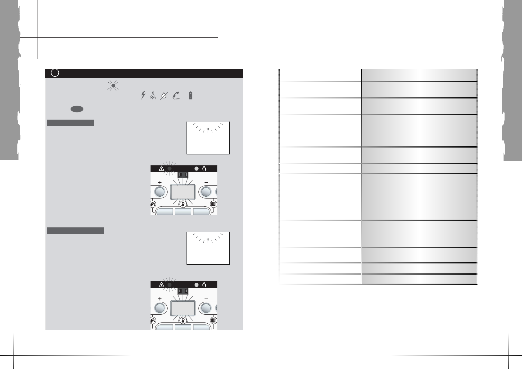
K
• If a fault occurs, the red lights on the boiler and on the room thermostat flash
and a pictogram is displayed on the thermostat : , , , or
• Press the button on the thermostat:
Fault level 1
• The thermostat shows the procedure to follow:
• At the same time, the boiler’s screen shows
the code for the fault:
OK
Fault indicators
SYSTEM PRESSURE
TOO LOW
FILL IN AT 1.5 BAR
21
Fault level 2
• The thermostat asks you to call your After-Sales service
engineer, informing him of the fault code flashing on the boiler
to assist in his diagnosis.
• At the same time, the boiler’s screen
shows the code for the fault:
FLOW RATE FAULT
CALL AFTERSALES
TEL 00 00 00 00 00
23
Page 10
INSTALLERS
1918
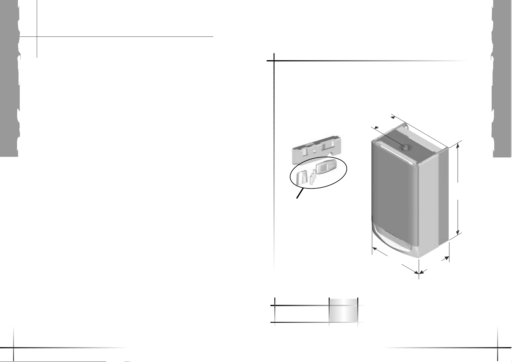
Dimensions
The boiler is delivered in
one package :
the boiler itself, the wireless
thermostat, the fixing
bracket, the template and
pipe connections .
The different packages
relating to the flue system
will be ordered depending
on the actual configuration
of the installation
418
890
510
232
Isofast F 35E
Net weight (kg) 52
Gross weight (kg) 60
The “as delivered” package consists of :
- 1 wireless thermostat
- 1 fixing bracket
- 3 x 1.5 V alkaline battery cells type LR6
- 1 access cover to the battery cells
ATTENTION: DO NOT FORGET TO RECOVER
THE ROOM THERMOSTAT placed in a
polystyrene case in the bottom of the package.
General Information
IMPORTANT NOTICE
The boiler and pipes are
supplied in one pack, the
flue is supplied seperately.
This boiler is factory set for
use only on G20 natural
gas.
Where no British Standards
exists, materials and
equipment should be fit for
their purpose and of suitable
quality and workmanship.
Refer to Manual Handling
Operations, 1992
regulations.
The installation of this boiler
must be carried out by a
competent person in
accordance the rules in
force in the countries of
destination.
Manufacturer’s instructions
must not be taken as
overriding statutory
requirements.
Sheet Metal Parts
WARNING: When installing
the appliance, care should
be taken to avoid any
possibility of personal injury
when handling sheet metal
parts.
Statutory Requirements
The installation of the boiler
MUST be carried out by a
competent person in
accordance with the relevant
requirements of the current
issue of : Manufacturer’s
instructions, supplied.
The Gas Safety (Installation
and Use) Regulations, The
Building Regulations, The
Building Standards
(Scotland) Regulations
(applicable in Scotland),
local Water Company
Bylaws, The Health and
Safety at Work Act, Control
of Substances Hazardous
to Health, The Electricity at
Work Regulations and any
applicable local regulations.
Detailed recommendations
are contained in the current
issue of the following British
Standards and Codes of
Practice, BS4814, BS5440
Part 1 and 2, BS5449,
BS5546, BS6700, BS6798,
BS6891 and BS7074 Part 1
and 2, BS7478, BS7593,
BS7671.
We also suggest that you
have to hand a copy of the
British Gas publication,
“Guidance Notes for the
Installation of Domestic
Condensing Boilers”.
Manufacturer’s notes must
not be taken as overriding
statutory obligations.
Certification
This boiler certificated to the
current issue of EN 483 for
performance and safety.
It is important that no
alteration is made to the
boiler, without permission, in
writing, from Saunier Duval.
Any alteration that is not
approved by Saunier Duval.,
could invalidate the warranty
and could also infringe the
current issue of the
Statutory Requirements.
Electrical Supply
All system components shall
be of an approved type and
all wiring to current I.E.E.
wiring regulations.
External wiring must be
correctly earthed, polarised
and in accordance with the
relevant standards.
In GB this is BS 6891.
In IE this is the current
edition of I.S.813 "Domestic
Gas Installations".
The boiler must be
connected to a permanent
230V ac, 50Hz supply.
Connection of the whole
electrical system of the
boiler, including any heating
controls, to the electrical
supply must be through one
common isolator and must
be fused 3 Amp maximum.
Wiring to the boiler must be
PVC 85°C insulated cable,
not less than 0.75mm2
(24/0.20mm).
Page 11
INSTALLERS
2120
Natural Gas (G 20) F 35 E
Ø burner injector (mm) 5,65
inlet pressure (mbar) 20
Sanitary flow rate at maximum input (m
3
/h) 3,62
Heating flow rate at maximum input (m
3
/h) 3,02
Flow rate at minimum input (m
3
/h) 0,85
Electricity F 35 E
Electrical supply (V) 230
Electrical rating (A) 0,9
Maximum absorbed power (W) 206
IP classification IPX4D
Class 1
Technical Data
Isofast
Heating F 35 E
Heating output at 80°C/60°C (P) adjustable (kW) from 7,6 to 28
(BTU/H) from 25,930 to 95,536
Heating input min. (Q) (kW)/(BTU/H) 8 / 27,296
Heating input max. (Q) (kW)/(BTU/H) 28,6 / 97,583
SEDBUK efficiency (%) ?
Heating output at 50°C/30°C adjustable (kW) from 8,6 to 30,6
Maximum heating temperature (°C) 80
Minimum heating temperature (°C) 22
Expansion vessel charge pressure (bar) 0,5
Maximum system capacity at 75°C (l) 215
Safety valve, maximum service pressure (PMS) (bar) 3,0
Hot water F 35 E
Heating output (P) adjustable from… (kW)/(BTU/H) 34,2 / 116,690
to… (kW)/(BTU/H) 7,6 / 25,931
Maximum hot water temperature (°C) 60
Threshold flow rate (l/min.) 1
Specific flow rate (D) (for 30°C temp rise) (l/min.) 16,3
Storage capacity (l) 4
Expansion valve setting (bar) 10
Minimum operating pressure (bar) 0,7
Maximum operating pressure (P
MW) (bar) 10
Combustion F 35 E
Product outlet diameter (mm) 60
Fresh air inlet diameter (mm) 100
Fresh air flow rate (1013 mbar - 0°C) (m
3
/h) 43
Product outlet flow rate (g/s) 15,3
Product outlet temperature (°C) 68
Values of product outlet CO (ppm o mg/kWh) 100 or 176
CO2 (%) 9,2
NOx (ppm o mg/kWh) 21,1 or 37,3
Gas Supply
The gas installation must be
in accordance with the
relevant standards.
In GB this is BS6891.
In IE this is the current
edition of I.S.813 "Domestic
Gas Installations".
The supply from the
governed meter must be of
adequate size to provide a
steady inlet working
pressure of 20mbar (8in wg)
at the boiler.
On completion, test the gas
installation for soundness
using the pressure drop
method and suitable leak
detection fluid, purge in
accordance with the above
standard.
Technical Data
All dimensions are given in
millimetres (except as
noted).
The data label is positioned
on the inner door.
The Seasonal Efficiency
Domestic Boilers UK
(SEDBUK) is Band 'A'.
The value is used in the UK
Government's Standard
Assessment Procedure
(SAP) for energy rating of
dwellings. The test data
from which it has been
calculated has been certified
by B.S.I.
F 35 E
Gas category II2H3P
Page 12
INSTALLERS
2322
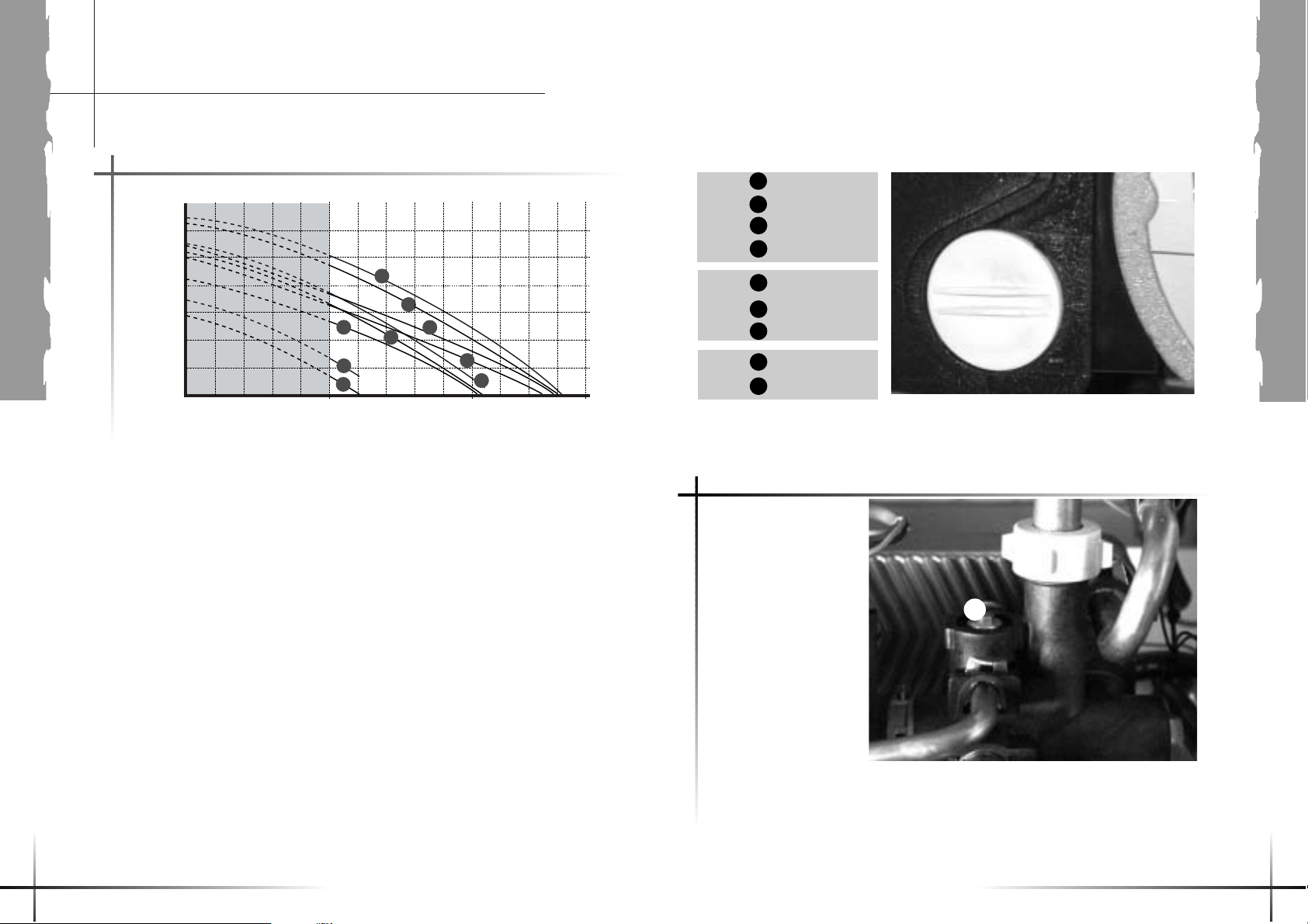
By-pass fully shut
Open 1/2 turn
By-pass fully shut
Open 1/4 turn
Open 1/2 turn
Open 2 turns
1
2
NB : Factory seeting : Speed II
III
II
I
Speed III
Bypass
The Isofast boiler has a
built-in bypass. This must
be adjusted according
to the requirements of the
system, refer to the flow
rate pressure curve.
The boiler is supplied with
the built-in bypass open
a half a turn. It is
adjusted by turning the
bypass screw (a).
Turn the screw clockwise
to close the bypass.
When using thermostatic
radiator valves (TRV’s)
on all of the radiators, it is
essential that a separate,
adjustable bypass of 15 mm
minimum diameter is fitted
between the flow and return
of the heating circuit.Any
bypass must be fitted before
system controls.
a
By-pass fully shut
Open 1/4 turn
Open 1/2 turn
70
60
50
40
30
20
10
500 14001000
2
3
9
7
8
6
1
4
5
Curve output/pressure
Available pressure (kPa)
between heating supply and return lines
Flow rate through heating system (l/h)
Technical Data
Speed II
Speed I
3
4
5
6
7
8
9
Page 13

INSTALLERS
2524
1
3
22
AB C DE
2
8
9
7
10
14
13
12
11
19
24
15
16
17
18
20
21
23
25
26
27
28
29
30
31
32
6
3
4
5
Isofast F 35 E
Schematic layout of boiler
1-Flue outlet
2-Main heat exchanger
3-Burner
4-Ignition and controle
electrode
5-Fan
6-Gas control valve
7-DHW storage vessel
8-Condensate drain
9-Overheat safety
thermostat.
10 - Temperature sensor for
DHW storage vessel
11 - Expansion vessel
12 - Heating return
thermistor
13 - Heating outlet
thermistor
14 - Ignition module
15 - Pump
16 - Water pressure sensor
17 - Domestic plate to plate
heat exchanger
18 - Three way valve
19 - Heating element
20 - Drain cock
21 - Water flow sensor
22 - Discharge safety valve
3 bars
23 - DHW temperature
sensor
24 - Discharge safety valve
10 bar
25 - Isolating valve
26 - Filter on cold water inlet
27 - Filling system
28 - Filter on heating circuit
29 - Isolating valve
30 - Isolating valve
31 - Isolating valve
32 - Isolating valve
A-Heating return
B-Cold water inlet
C-Heating flow
D-Domestic hot water
outlet
E-Gas
a-Flue outlet
b-Overheat safety
thermostat.
c-Combustion chamber
d-Expansion vessel
e- Air/Gas mixture inlet
f-Ignition and control
electrode
g-Fan
h-Gas control valve
i-Ignition module
j-Condensate drain
k-Heating flow
thermistor
l-Heating return
thermistor
m-Water flow sensor
n-Water pressure sensor
o-Pump
p-Filter on cold water
inlet
q-Domestic plate to plate
heat exchanger
r-Discharge safety valve
10 bar
s-Discharge safety valve
3 bar
t-Filling system
u-Drain cock
v-Room thermostat plug
w-Control panel
Boiler components
Isofast F 35 E
a
b
c
d
f
e
j
k
l
m n
q
r
t
u
v
w
g
h
i
s
o
p
Page 14

INSTALLERS
2726
installed in a timber frame
building it should be fitted in
accordance with the
Institute of Gas Engineers
document IGE/UP/7/1998.
If in doubt seek advice from
the local gas undertaking or
Saunier Duval.
• The boiler is room sealed,
so when it is installed in a
room or space, a permanent
air vent is not required.
• Due to the high efficiency
and hence low casing
temperature of this boiler,
cupboard or compartment
ventilation is not necessary.
Boiler location
• This boiler is not suitable
for outdoor installation.
• This boiler may be
installed in any room,
although particular attention
is drawn to the installation of
a boiler in a room containing
a bath or shower where
reference must be made to
the relevant requirements.
In GB this is the current
I.E.E. WIRING
REGULATIONS and
BUILDING REGULATIONS.
In IE reference should be
made to the current edition
of I.S.813 "Domestic Gas
Installations" and the current
ETCI rules.
• The boiler should be
positioned so that at least
the minimum operational
and servicing clearances are
provided, see diagram
opposite.
Additional clearances may
be beneficial around the
boiler for installation and
servicing.
For flue installations where
external access is not
practicable, consideration
should be given for the
space required to insert the
flue internally, which may
necessitate clearance larger
than those specified in
diagram.
• If the boiler is to be
Leave existing air vents.
A template is supplied with
the fixing bracket.
Position setting of the
assembly shall be
performed in compliance
with the indications shown
on the template.
Use two or three screws for
the fixing bracket.
The mechanical
characteristics of the screws
shall – at least – meet the
requirements specified on
the sketches below. Also,
they shall be suited to the
characteristics of the carrier
wall.
16 kg mini
33 kg mini
16 kg mini
33 kg mini
If the boiler is not
immediately installed,
protect the different
couplings so that no plaster
or paint could jeopardize the
tightness of subsequent
connections.
232
GAS
70 102 702115
20 mini
160
11875066
160
Ø 105
890
510
Page 15

INSTALLERS
2928
Flue location and Ventilation
Flue Position and Length
The standard horizontal flue
is fitted onto the top of the
boiler using the flue elbow.
See diagrams to determine
whether a standard flue can
be used.
An elevated flue system can
be installed with the addition
of a vertical flue adapter,
extension kits and elbow,
see section flue options.
When extension pipes are
used the flue system must
be designed to have a
continuous fall to the boiler
of at least 3% to allow
condensate to run back into
the boiler and out via the
drain.
Internal Flue Installation
The flue can be installed
from inside the building,
when access to the outside
wall face is not practicale.
Additional accessories are available.
See Saunier Duval "Flue Options Guide" for
configurations available.
Minimum siting dimensions for fanned flues terminals
poritions
Horizontal flues
A-directly below an opening, air brick,
opening windows . . . . . . . . . . . . . . . . . . . . . . . . .300
B-above an opening, air brick, opening windows . . . .300
C - horizontally to an opening, air brick,
opening windows . . . . . . . . . . . . . . . . . . . . . . . . .300
D- below gutter, drain/soil pipe . . . . . . . . . . . . . . . . . . .25
E-below eaves . . . . . . . . . . . . . . . . . . . . . . . . . . . . .25
F-below a balcony or car port . . . . . . . . . . . . . . . . . .25
G- from vertical drain pipes and soil pipes . . . . . . . . . .25
H- from internal/external corners . . . . . . . . . . . . . . . . .25
H*- to a boundary alongside the terminal . . . . . . . . . . .300
I-above adjacent ground or balcony level . . . . . . . . .300
J-from surface or a boundary facing the terminal . . .600
K-facing terminals . . . . . . . . . . . . . . . . . . . . . . . . .1200
L-from opening (door/window) in car port
into dwelling . . . . . . . . . . . . . . . . . . . . . . . . . . . .1200
M - vertical from a terminal . . . . . . . . . . . . . . . . . . . .1500
N - horizontally from a terminal . . . . . . . . . . . . . . . . . .300
Vertical flues
P-from another terminal . . . . . . . . . . . . . . . . . . . . . .600
Q- above roof level . . . . . . . . . . . . . . . . . . . . . . . . . . .300
R-from adjacent opening window . . . . . . . . . . . . . .1000
S-from adjacent wall to flue . . . . . . . . . . . . . . . . . . . .300
H* and J* : These dimensions comply with the building regulations, but they may need to
be increased to avoid wall staining and nusance from pluming depending on site conditions.
Warning notice :
Use only flue accessories
developed for
Saunier Duval condensing
boilers.
Page 16

INSTALLERS
3130
Flue location and Ventilation
• Terminal Position
The minimum acceptable
siting dimensions for the
terminal from obstructions,
other terminals and
ventilation openings are
shown in page 29. For
Ireland the minimum
distances for flue terminal
positioning must be those
detailed in I.S.813 "Domestic
Gas Installations".
The terminal must be
exposed to the external air,
allowing free passage of air
across it at all times.
Being a condensing boiler
some pluming may occur
from the flue outlet. This
should be taken into
consideration when
selecting the position for the
terminal.
It may be necessary to
increase dimensions H & J if
there is a risk that the boiler
products could stain any
adjoining surface.
Carports or similar
extensions of a roof only, or
a roof and one wall, require
special consideration with
respect to any openings,
doors, vents or windows
under the roof. Care is
required to protect the roof if
made of plastic sheeting. If
the carport comprises of a
roof and two or more walls,
seek advice from the local
gas supply company before
installing the boiler.
• Terminal Guard
A terminal guard is required
if persons could come into
contact with the terminal or
the terminal could be
subject to damage.
If a terminal guard is
required, it must be
positioned to provide
minimum of 50mm
clearance from any part of
the terminal and be central
over the terminal.
3%
The flue system pipes must
feature a slope of 3%
towards the boiler in order
to recover any condensates.
Attention : The flue system
terminal supplied by Saunier
Duval already integrates this
slope. Therefore, it shall be
applied to any flue system
extensions.
L
64
Gasket
The maximum head loss
is reached with an elbow
and flue system length (L)
of 10 m.
Horizontal flues (installation type C13)
Page 17

INSTALLERS
3332
Heating system
General
The boiler is for use only
with sealed central heating
systems.
The safety valve is an
integral part of the boiler
and it cannot be adjusted.
The digital readout on the
controls fascia indicates the
system pressure when there
is no central heating
demand.
The circulation pump is
integral with the boiler.
Expansion vessel
The boiler has an integral
expansion vessel with a
capacity of 10 litres, with a
charge pressure of 0.5 bar.
Note : The expansion vessel
volume depends on the total
water system volume and
the initial system design
pressure. Guidance on
vessel sizing is also given in
the current issue of BS5449
and BS7074 Part 1, for IE
refer to the current edition of
I.S.813 "Domestic Gas
Installations".
Flow rate
If it is necessary to alter the
flow rate, the system can be
fitted with a lockable balancing
valve in the main flow or
return pipes shown as valve
"A" in diagram.
The flow rate through the
boiler must not be allowed
to fall below 14 l/min.
Bypass
The boiler is fitted with an
adjustable automatic
bypass. Ensure that under
no circumstances does the
flow rate drop below
14l/min.
The installation of the boiler
must comply with the
requirements of the current
issue of BS6798, in Ireland,
refer also to the current
edition of I.S.813 "Domestic
Gas Installations".
In GB it is necessary to
comply with the Water
Supply (Water Fittings)
Regulations 1999 (for
Scotland, the Water
Byelaws 2000, Scotland).
To comply with the Water
regulations your attention is
drawn to : The Water
Regulations guide published
by the Water Regulations
Advisory Service (WRAS)
gives full details of the
requirements.
Heating system
In IE the requirements given
in the current edition of
I.S.813 "Domestic Gas
Installations" and the current
Building Regulations must
be followed.
Water tratment
In the case of an existing
installation, it is ESSENTIAL
that prior to installing the
new boiler the system is
thoroughly flushed. For
optimum performance after
installation of a new system,
the boiler and its associated
central heating system
should also be flushed.
Flushing should be carried
out in accordance with
BS7593: 1992 using a
cleanser such as Sentinel
X300 or X400, Fernox
Superfloc or Salamander
corrosion guard cleaner.
For long-term corrosion
protection, after flushing, an
inhibitor suitable for stainless
steel heat exchangers
should be used, refer to the
current issue of BS 5449
and BS 7593 on the use of
inhibitors in central heating
systems. Examples are
Sentinel X100 Fernox or
Salamander corrosion guard
inhibitor.
Draining Tap
A draining tap must be
provided at the lowest
points of the system, which
will allow the entire system
to be drained.
A drain tap for the appliance
is provided as an integral
part of the hydroblock, see
diagram page 24.
General - All domestic hot
water circuits, connections,
fittings must be in
accordance with the
relevant standards and
water supply regulations.
Domestic Hot Water
System
For GB: Guidance G17 to
G24 and recommendation
R17 to R24 of the Water
Regulations Guide.
For IE: The current edition of
I.S.813 "Domestic Gas
Installations".
Water Pressure
The maximum working
pressure of the domestic
hot water circuit is 10 bar. If
the cold water supply
pressure exceeds this, then
a pressure-reducing valve
must be fitted in the supply
to the boiler.
'Hard' Water Areas
The temperatures within the
heat exchanger are limited
by the boiler control system
to minimise scale formation
within the hot water pipework.
However, in areas where the
water is 'hard' (i.e. more
than 200mg/litre), it is
recommended that the hot
water setting is reduced and
that a scale reducer is fitted.
Refer to the manufacturer's
instructions or consult the
local water company for
additional advice.
Domestic Water Flow Rate
The water flow rate is
restricted to a maximum 16
l/min by a restrictor fitted on
the cold water inlet.
Page 18

INSTALLERS
3534
2
Boiler
installation
Prior to performing any
operation, it is essential that
the piping systems be
flushed with a suitable
product in order to eliminate
any impurities such as
fillings, weld spatters, oils
and greases.
Such foreign materials could
be driven into the boiler, and
could impair its operation.
NB: Solvents may cause
damages to the piping
system.
Remove the wooden beam
placed behind the boiler.
Appliance Connection
IMPORTANT: With regards
to the Manual Handling
Operations, 1992
Regulations, the following lift
operation exceeds the
recommended weight for a
one man lift, refer to Manual
Handling section, on page 4.
The appliance will contain a
small amount of water,
place a water container
beneath the boiler
connections before
removing the protective
caps.
1 - Lifting the boiler into
position, lean the top of the
boiler slightly to the wall and
position just above the
hanging bracket.
2 - Lower the boiler slowly
and engage onto the
hanging bracket.
Connect isolating valves
using washers and domestic
flow restrictor supplied with
the boiler.
3 - Do not forget to connect
the blue extension on the
filling tap, as shown on the
picture below.
1
➡
➡
3
A
B
C
D
E
GAS
70
70
115
250
223
WALL
102
u
t
v
w
x
Piping
installation
Make connections to boiler, gas, water and heating cocks with the tube assemblies
supplied in piping pack as shown in the diagram below :
A-Heating return with isolating tap (t) and (u),
B-Cold water inlet with isolating tap (v) and water restrictor to 16 l/min,
C-Heating flow with isolating tap (w),
D-Domestic hot water outlet,
E-Gas inlet with isolating tap (x).
Water restrictor
16 l/min.
Pressure connection
Gas Connection
Before connection check
supply of local gas.
Refer also to page 18.
Do not subject the gas
service cock to heat.
Fit the sealing washer into
the union nut and make
good the connection to the
gas service cock on the
wall.
Make sure the on / off lever
is accessible.
The whole of the gas
installation, including the
meter, should be inspected,
tested for soundness and
purged in accordance with
the current issue of BS6891
and in IE the current edition
of I.S.813 "Domestic Gas
Installations".
A - C : Central heating
Ø 22 mm
B- D : Domestic hot
water Ø 15 mm
E : Gas supply Ø 15 mm
Page 19

INSTALLERS
3736
Water Connections
Flush out the domestic hot
water and the heating
systems before connecting
to the boiler.
Make the connections to the
domestic hot water and
heating systems by fitting
the sealing washers into the
securing nuts and make
good the connection to the
isolating valves.
Do not subject the isolation
valves to heat.
Make sure the drain point is
accessible.
• The heating return
coupling is equipped with a
filter, accessible after
removing the end nut.
•The proof-test pressure can
be read on a pressure gauge
screwed instead of the
heating return coupling end
nut (A).
u
A
t
Filter on heating
return (A)
A pressure gauge can be
screwed instead of the
heating return coupling
Piping
installation
Safety Discharge Valve
The pipes from the safety
discharge valves S1 and S2
must not discharge above
an entrance, window or any
type of public access area.
Take the short safety
discharge tube, union nut
and seal, supplied loose in
the boiler fittings pack and
fit as shown in diagram
below.
This must be extended,
using not less than 15mm
o.d. pipe, to discharge, in a
visible position, outside the
building, facing downwards,
preferably over a drain.
The pipe must have a
continuous fall and be
routed to a position so that
any discharge of water,
possibly boiling, or steam
cannot create any danger to
persons, damage to
property or external
electrical components and
wiring.
To ease future servicing it is
advisable to use a
compression type fitting
supplied with the boiler to
extend the safety discharge
valve tube.
s
2
s
1
Page 20

39
WARNING : This appliance
must be earthed.
This appliance must be
wired in accordance with
these instructions. Any fault
arising from incorrect wiring
cannot be put right under
the terms of the
Saunier Duval guarantee.
All system components
must be of an approved
type.
Electrical components have
been tested to meet the
equivalent requirements of
the BEAB.
Do not interrupt the mains
supply with a time switch or
programmer.
Connection of the whole
electrical system and any
heating system controls to
the electrical supply must be
through a common isolator.
Isolation should preferably
be by a double pole
switched fused spur box
having a minimum contact
separation of 3mm on each
pole. The fused spur box
should be readily accessible
and preferably adjacent to
the boiler. It should be
identified as to its use.
Mains Cable
Important: If a replacement
supply cable is required it
must be purchased from
Saunier Duval.
• The 630 mA fuse of the
PCB must be connected to
the neutral.
Electrical
connection
INSTALLERS
38
Connect the A elbow
Ø 22 mm to a discharge
system leading to the
sewer, in compliance with
the instructions below:
- Use a rigid PVC tube or a
flexible silicon pipe resistant
to condensate.
- The pipe must have a
continuous fall.
- Do not use copper pipes
Important notice :
The float of the condensate
recovery system also
ensures fume tightness.
Therefore, it is useless to
add water in the
condensate box.
Condensate
discharge
elbow.
Condensate box with
access plugs for cleaning
purposes.
Ø 22 mm
A
NO
YES
Piping
installation
Page 21

➡
Cold water
inlet
Heating
return
➡
Heating flow
INSTALLERS
4140
Commissioning on boiler
Please ensure the
"Benchmark" logbook is
completed and left with the
user .
Filling the system 1 to 8
The commissioning and first
firing of the boiler must only
be done by a qualified
registered person.
Make sure that the boiler is
connected to the electrical
supply and the gas service
cock is open.
Switch ON (I). Open the isolating
taps (t), (u), (v) and (w)
on boiler: slot in line wi th
the lenght of the valve
21
Undo cap on automatic air vent
on top of pump and leave undone.
Fill the system until the pressure
indicated on the display is
between 1 and 2 bar.
Close filling device.
4
3
v
t
w
Bleed each radiator to remove
the air, re-tighten bleed screws.
Leave the cap on the pump
auto air vent open.
6
5
➡
Open various hot water taps
to bleed system.
Make sure the display indicates
a system pressure of between
1 and 2 bar. Re-fill system as necessary.
8
7
1,5 bar
u
Page 22

INSTALLERS
Commissioning on boiler
4342
Press the key to
operate the boiler without
room thermostat.
• Adjust heating temperature
to maximum.
• Allow the temperature to
rise to the maximum value,
with all radiator valves open.
The temperature rise will
cause release of the gases
contained in the water of the
central heating system.
• Gases driven towards the
boiler will be automatically
released through the
automatic air vent.
• The gases trapped at the
highest point of the system
must be released by bleeding
the radiators. Check the
burner gas rate required, ten
minutes from lighting. Refer
to Data Label on electrical
controls box. Should there
be any doubt about the gas
rate it should be checked at
the meter. On reaching
maximum temperature, the
boiler should be turned off
and the system drained as
rapidly as possible whilst still
hot.
• Refill system to a pressure
of between 1 and 2 bar and
vent as before.
• Restart boiler and operate
until a maximum temperature
is reached. Shut down boiler
and vent heating system.
If necessary, top up heating
system and make sure that
a pressure of at least 1 bar
is indicated when system is
COLD.
Flush the domestic hot water
system by opening the hot
water taps for several
minutes.
Instruct the User
• Instruct and demonstrate
the lighting procedure and
advise the user on the safe
and efficient operation of the
boiler.
• Instruct on and demonstrate
the operation of heating
system control.
• Advise the user on the use
and maintenance of any
scale reducer and pass on
any relevant instructional
documents.
• Advise that to ensure the
continued efficient and safe
operation of the boiler it is
recommended that it is
checked and serviced at
regular intervals. The
frequency of servicing will
depend upon the installation
conditions and usage, but in
general, once a year should
be enough.
• Draw attention, if
applicable, to the current
issue of the Gas Safety
(Installation and Use)
Regulations, Section 35,
which imposes a duty of
care on all persons who let
out any property containing
a gas appliance in the UK.
• The user shall not interfere
with or adjust sealed
components.
• It is the Law that any
servicing is carried out by a
competent person.
• Advise the user that, like
all condensing boilers this
appliance will produce a
plume of condensation from
the flue terminal in cool
weather. This is due to the
high efficiency and hence
low flue gas temperature of
the boiler.
• Advise the user of the
precautions necessary to
prevent damage to the
system, boiler and the
building, in the event of the
heating system being out of
use during frost or freezing
conditions.
• Advise the user that the
permanent mains electrical
supply SHOULD NOT be
switched off, as the built in
frost protection and
pump/valve saver program
would not be operable.
• Reminder, leave these
instructions and the
‘Benchmark’ logbook with
the user.
• For IE, it is necessary to
complete a "Declaration of
Conformity" to indicate
compliance to I.S.813. An
example of this is given in
the current edition of
I.S.813.
Page 23

INSTALLERS
4544
Settings
The description below
specifies the operations to
be performed to make
adjustments to an
installation fitted with
radiators or for
a direct floor system.
For other types of
installation (for example
with a floor-heating
system) , follow the
instructions in the
appropriate accessories
manual.
Your installation consists of a single radiator zone or direct floor system
1/3
Access to the boiler’s
technical data
(reserved for use by the
installers and After-Sales
service personnel).
This enables adjustments
to be made and any
malfunctions to be
analysed :
Commissioning on room thermostat
The wireless room thermostat
(R.O.) has been specially
developed for the Isofast.
• It is powered by 3 LR6
1.5V alkaline batteries.
• The boilers various
functions are parametered
from the room thermostat.
Installing the room
thermostat
• Fasten the bracket for the
room thermostat on an
internal wall approximately
1.50 m from the floor, in an
area sheltered from direct
sunlight and any source of
interference, such as
television, lamps, draughts,
etc.
• Insert the batteries in the
thermostat.
When commissioning for
the first time, At initial
commissioning stage, the
boiler automatically shifts to
manual mode (the control
panel keys are lit, and
the key is blinking),
thus meaning that the
wireless room thermostat
has not yet been
acknowledged by the boiler.
To do this :
• Open the control panel
• Locate connector (A) on
the left-hand side and insert
it in the thermostat for a few
seconds as shown in the
photo opposite.
When the red indicator light
stops flashing, this shows
that the boiler has
recognised the thermostat.
A
LCD display
Confirm OK
Access to the menus
Weekly
programme
Scroll
Up/Down
Return
Mains power point
or power cable
Fault indicator (red)
Wall
bracket
A
Your installation consists of a single radiator zone or direct floor system
Progress of the operations :
1 - Accessing the installer menu
• Connect connector (A) to the room thermostat as detailed on the previous page.
• Press for 5 seconds to call up the following menu :
• Select installer menu :
2 - Select the language
3 - Installation configuration
MENU
INSTALLER MENU
SELECT THE LANGUAGE
INSTALLATION TYPE
Please note that pressing button
at any time takes you back to the previous step.
OK
OK
ACCESS CODE
96
+
+
OK
+
INSTALLER MENU
AFTERSALES MENU
FAULT HISTORY
BOILER DATA
OK
1 RADIATOR ZONE
CHOOSE LANGAGE
INSTALLATION TYPE
RADIO SATELLITE
HEATING REGULATION
BOILER CONFIG.
ENGLISH
C
OK
OK
Page 24

INSTALLERS
4746
f
Your installation consists of a single radiator zone or direct floor system
3/3
Settings
Your installation consists of a single radiator zone or direct floor system
2/3
4 - Radio accessories
RADIO SATELLITE
5 - Heating control
HEATING CONTROL
Selecting is recommended so that you can benefit from automatic
circuit temperature control.
However, if you wish to adjust the radiator temperature yourself, select
Then return to the user menu to set the radiator temperature.
AUTO
a/ Press for 5 seconds
b/
MENU
6 - Boiler configuration
BOILER CONFIG.
Warning : This menu must only be used when installing one or more of
these accessories > please refer to the section on "Activating the
accessories".
OK
OK OK
SET RADIATOR T¡
OK
IN OUTDOOR SENSOR OFF
REPEATER OFF
THERMOSTAT 2 OFF
MODEM OFF
HEATING SETPOINT
OK
+
MAX OUTPUT
CHIMNEY SET
MAX RADIATOR T¡
MIN RADIATOR T¡
PUMP MODE
MANUAL
SET RADIATOR T¡
50¡C
OK TO VALIDATE
AUTO
MANUAL
6.2 Adapting the length of the vent
CHIMNEY SET
6.3 Selecting the maximum radiator temperature
MAX RADIATOR T¡
6.4 Selecting the minimum radiator temperature
MIN RADIATOR T¡
6.5 Selecting the pump’s operation
PUMP MODE
Operation WITH THERMOSTAT is recommended in all cases except for direct floor heating,
in which case you should select:
6.6 Choice of preheat
In ON mode, the boiler holds the exchanger at the required temperature between 5 O’clock a.m.
and 11 O’clock p.m. in order to warrant optimal reactivity for the supply of sanitary hot water.
In AUTO mode, the boiler memorizes the day to day requirements of the family, and triggers the
pre-heating a few minutes before the first use of sanitary hot water of the day.
In OFF mode, the function is inhibited.
WITH THERMOSTAT
PREHEAT
No setting is required for this type of boiler. Codes displayed do not af
functionning of the boiler.
OK
OK
OK
PERMANENT
OK
MAX 73¡C
MAX 65¡C
MAX 50¡C
MIN 50¡C
MIN 38¡C
MIN 28¡C
MIN 22¡C
WITH BURNER
WITH THERMOSTAT
PERMANENT
OFF
AUTO
ON
Warning : for direct floor systems,
do not exceed a temperature of 50°C.
OK
OK
OK
6.1 Limiting the maximum heating power
MAX OUTPUT
OK
/...
16kW
15kW
14kW
/...
OK
WHEN YOU HAVE COMPLETED PARAMETERS, press for approx. 5 seconds
to return to the initial display.
MENU
Page 25

INSTALLERS
4948
OK
EXT. SENSOR ON
HEATING REGULATION
BOILER CONFIG.
CHOOSE LANGUAGE
+
C
• Reach into the Heating Set Point menu to select the desired regulating mode.
Select the code following curves given on diagram below.
NB: Zone 2 settings are only displayed when two heating zones have been selected in the “config.
Installation” menu.
MANUAL
AUTO
AUTO
OK
HEATING SETPOINT
T¡ HEATING OFF
T¡ HEATING OFF
HEATING SETPOINT
Note : we recommend selecting 17 or 18°C.
You may retain the advantages conferred by the external sensor, while setting yourself the slopes
of the sensor. Select the setting and adapt the following parameters :
OK OK
CORRECT T¡ ZONE1
SLOPE ZONE 2
SLOPE ZONE 1
CORRECT T¡ ZONE2
0,70,80,60,2
......
OK OK
1,61,51,40,2
4,0
4,0
......
... ...
OK OK
... ...
OK OK
... ...
OK OK
Temperature
setting curves.
30
-30 -20 -10 100
40
50
60
70
80
90
100
Heating temperature outlet (°C)
Outside
temperature (°C)
b/ T° heating off
a/ Heating setpoint
2.2 Heating setpoint
0,2
0,5
0,7
1,0
1,2
1,5
1,7
2,0
2,2 2,5 2,7 3,0 3,5 4,0
MANUAL
The setting is recommended to obtain automatic regulation of circuit temperatures. In
such case, no slope adjustment is required. The boiler will itself select, after a few days, the slope
which is the most suited to the heating installation.
49
Accessories settings
2/3
Settings
Accessories settings
OK
OK
C
INSTALLER MENU
• Press for 5 seconds to call up the following menu:
Progress of the operations :
RADIO ACCESSORIES
HEATING REGULATION
BOILER CONFIG.
INSTALLER MENU
AFTERSALES MENU
FAULT HISTORY
BOILER DATA
ACCESS CODE
96
OK
OK
RADIO ACCESSORIES
EXT. SENSOR OFF
REPEATER OFF
THERMOSTAT 2 OFF
MODEM OFF
EXT. SENSOR OFF
EXT. SENSOR ON
REPEATER OFF
THERMOSTAT 2 OFF
MODEM OFF
CONNECT
+
+
MENU
1 - Access to the Radio accessories menu
• Select the installer menu:
• Select the Radio accessories menu:
Please note that pressing button
at any time takes you back to the previous step.
2.1 External sensor recognition
OK
2 - External sensor
The external sensor is now operating
Hold the satellite button, situated on the backside of
the external sensor box, depressed for 10 seconds.
To establish connection, the sensor transmits
signals – this may require several minutes – until it
is acknowledged by the room thermostat which
then validates the connection through the following
display :
• Connect connector (A) on the room thermostat as described page 44.
1/3
Page 26

Selecting the language on the thermostat’s display.
Selecting the type of heating installation.
The ON position of this menu assigns the TA1
clock function to the radiator zone. In such case,
the ambient temperature at floor level is selected
from the TA1 user’s menu.
Activating the various radio accessories on the
installation.
Selecting Automatic or Manual control mode.
In Automatic mode, the radiator temperature
adapts automatically to the heating requirements of
the room in which the thermostat is located, operating between the maximum and minimum temperature values set.
Selecting the boiler’s main operating parameters
(power and heating circuit temperatures, pump
mode and airflow configuration).
INSTALLERS
5150
Glossary for the
installater menu
Select the language
Installation config.
Clock zone 2
Radio accessories
Heating regulation
Boiler config.
Settings
Accessories settings
OK
REPEATER OFF
REPEATER ON
THERMOSTAT 2 OFF
MODEM OFF
EXT. SENSOR OFF
CONNECT
The repeater is now operating
OK
OK
3 - Repeater
OK
THERMOSTAT2 OFF
THERMOSTAT 2 ON
MODEM OFF
EXT. SENSOR OFF
REPEATER OFF
CONNECT
The room thermostat 2 is now operating
C
4 - Room thermostat 2
Hold the satellite button situated on the
back side of the radio relay box
depressed for 10 s.
To establish the connection, the radio
relay transmits signals until it is
recognized by the room thermostat
which validate the connection by the
following display :
Disconnect the cable of the zone 1 room
thermostat, and connect it to thermostat
2. This is sufficient to have it recognized
by the boiler.
Take the cable and reconnect it to zone
1 room thermostat and press the
key. The following display will confirm
the connection:
3/3
Page 27

INSTALLERS
5352
2/ Minimum HEATING input
setting, through the CO2 :
a - Connect a CO2 analyser
to sample point B of the
adapter or flue elbow.
b - Adjust the boiler at its
minimum heating power
using the room thermostat
menus described in the
below.
c - Perform a heating
demand and record the
CO2 value after stabilization
(2 minutes or so).
d - Adjust the screw D to
obtain the G31 CO2 value
stated in the table, taking
the following principle into
account :
To increase the CO2 value,
turn the screw clockwise
To decrease the CO2
value, turn the screw
anti-clockwise
Note : After re-installation of
the sealed front face, the
CO2 value changes, and
must correspond to that
given in the table.
3/ After setting and
reassembly, restore the
maximum heating power to
its initial value (20 kW) and
stick the gas data tag close
to the nameplate.
Gas conversion
Your Isofast boiler is
factory-set to operate with
G20 gas.
For operation with G31 gas,
some adjustments must be
made on the gas valve after
removal of the sealed front
cover in order to obtain the
CO2 values given in the
adjacent table.
1/ Maximum hot water
input setting, through the
CO2.
a - Connect a CO2 analyser
to sample point B of the
adapter or flue elbow.
b - Fully open a hot water
tap.
c - Wait for 2 minutes or so,
until the CO2 reading has
stabilized.
d - Adjust the screw C to
obtain the G31 CO2 value
stated in the table, taking
the following principle into
account:
To increase the CO2 value,
turn the screw anti-clockwise
To decrease the CO2 value,
turn the screw clockwise
Note : After re-installation of
the sealed front face, the
CO2 value changes, and
must correspond to that
given in the table.
Isofast F 35 E G20 G31
Heating output max. hot water kW 34,2 34,2
Heating output max. heating kW 6,4 6,4
C02 case off % 9±0,2 10,3±0,2
C02 case on % 9,2±0,3 10,5±0,3
B
C
D
1 - Access to the installer menu
• Connect A connector on the room thermostat as indicated page 44.
• Press for 5 seconds to call up the following menu:
MENU
• Select the Installer menu:
INSTALLER MENU
2 - Access to boiler configuration
BOILER CONFIG.
• Set MAX OUTPUT on the minimal value:
MAX OUTPUT
WHEN YOU HAVE COMPLETED PARAMETERING, press for approx. 5 seconds
to return to the initial display.
OK
+
OK
ACCESS CODE
96
OK
+
INSTALLER MENU
AFTERSALES MENU
FAULT HISTORY
BOILER DATA
OK
MAX OUTPUT
CHIMNEY SET
MAX. RADIATOR T¡
6 kW
5 kW
MENU
CHOOSE LANGUAGE
INSTALLATION TYPE
RADIO SATELLITE
HEATING REGULATION
BOILER CONFIG.
/...
OK
OK
Page 28

Push the gas pipe upwards
further into gas valve
connection and then rotate
anti-clockwise (looking
down) until the gas pipe end
is over the large hole in
boiler chassis. Withdraw the
gas pipe from gas valve
connection and remove.
Note : When replacing
ensure that the sealing
grommet, situated below
the gas valve is correctly
re-seated.
Disconnect the gas valve
electrical plug at the gas
valve.
Disconnect the electrical
leads from the fan.
Remove the five combustion
chamber front retaining
nuts, see diag. 5.
Gently remove the fan, gas
valve and burner assembly
from the combustion
chamber, see diag. 5.
Clean the burner with a soft
brush taking great care not
to damage the front
insulation. DO NOT use
wire or sharp instruments to
clean the holes of the
burner.
Inspect the burner for any
signs of damage.
Inspect the sealing rings
and replace if necessary.
Removal of the burner is not
necessary during a normal
service.
NOTE : IF THE BURNER
HAS TO BE REMOVED IT
WILL REQUIRE A NEW
GASKET WHEN REFITTED.
INSTALLERS
5554
Servicing
Important Notes
To ensure the continued
efficient and safe operation
of the boiler it is
recommended that it is
checked and serviced at
regular intervals. The
frequency of servicing will
depend upon the particular
installation and usage, but in
general once a year should
be enough.
It is the Law that any
servicing is carried out by a
competent person.
When replacing a part on
this appliance, use only
spare parts that you can be
assured conform to the
safety and performance
specification that we require.
Do not use reconditioned or
copy parts that have not
been clearly authorised by
Saunier Duval.
General
Measurement of the
products of combustion can
be achieved by connection
of a probe to the
combustion analyser test
point, see diagram 1.
IMPORTANT NOTE :
Products of combustion will
be discharged when the cap
is removed. It is important to
replace the cap immediately.
Before commencing with a
service or replacement of
parts, the boiler should be
isolated from the electrical
supply and the gas supply
should be turned off at the
gas isolation valve, see
page 35.
All routine servicing
requirements can be
achieved by the removal of
the front panel and inner
panel only. To remove simply
undo the two screws on the
underside of the front panel
and lift off. Undo the two
screws on the front of inner
panel and lift off, see diag. 2.
Unless stated otherwise any
part removed during
servicing should be replaced
in the reverse order to
removal.
Servicing should always
include the removal of any
debris from the condensate
pipe and siphon.
After completing any
servicing of gas carrying
components, ALWAYS test
for gas soundness and carry
out a functional test of the
controls.
Spark Electrode
Disconnect the electrode
lead and two securing
screws. Withdraw the spark
electrode carefully from the
combustion chamber, see
diagram 3.
Inspect the tips for damage.
Clean away any debris and
check the spark gap is 3.5
to 4.5 mm.
Check the electrode gasket
for signs of damage and
replace if necessary.
Burner
Drop down the control panel
into the service position.
Disconnect the gas supply
at the gas service cock.
Remove the two gas pipe
retaining clips, one located
below gas valve and the
other one located on the
underside of the boiler
chassis.
Pull sealing grommet down
gas pipe diagram. 4.
Diagram 1
Combustion
analyser test point
Diagram 2
Torx screws
Diagram 3
Diagram 4 Diagram 5
Sealing
grommet
Gas pipe
retaining clip
Electrode
Gasket
Spark Gap 3.5 to 4.5
Heat exchanger
Combustion
chamber
Burner
Sealing ring
Gas valve
Fan
Securing
Nut (5)
Page 29

Draining of Boiler Heating
Circuit
Drain down the Heating
Circuit of the boiler only, by
closing the heating flow and
return isolating taps (t, u
and w), on the boiler
connections, see diag. 10.
Attach a length of hose to
the drain point and open the
drain valve (r), see diag. 9.
After servicing or replacing
parts, close the drain valve
and remove the hose. Open
the heating flow and return
isolating valves and refill,
vent and pressurise the
heating circuit.
Check for leaks.
Draining of Boiler Hot
Water Circuit
Drain the Domestic Hot
Water circuit by closing the
cold-water isolation tap (v)
on the boiler connection.
Open one or more hot water
taps to drain the hot water
circuit.
After servicing or replacing
parts open the cold-water
isolation valve and slowly
open a hot water tap to
remove air. Close the hot
water tap and check for any
leaks.
Inner Casing Panel Seal
Check.
Check the condition of the
seal, replace as required.
To replace remove the old
seal, thoroughly clean the
casing sufaces. Fit the new
seal, it is supplied to the
correct length.
➡
Cold water
inlet
Heating
return
➡
Heating flow
v
t
u
INSTALLERS
Servicing
5756
Combustion Chamber and
Heat Exchanger
Remove loose debris from
combustion chamber using
a soft brush and vacuum
cleaner. Carefully flush by
spraying water removing any
remaining debris through the
condensate trap (Ensure the
water is kept away from
electrical components).
Condensate Drain
The condense drain does
not normally need removing
during servicing.
To flush the condense drain
carefully pour water into the
heat exchanger and check
that water flows freely to
drain.
Combustion Check.
If a gas carrying component
has been replaced, the
combustion of the appliance
should be checked. Once
the appliance has been
re-assembled (apart from
the front and inner casing
panels) connect a CO2
combustion analyser to the
test point on the flue adapter,
and follow indications given
on page 52-53.
Domestic Cold Water Inlet
Filter
If the water flow rate
through the appliance has
reduced it may be
necessary to clean or
replace the water inlet filter.
Turn off the electrical supply
to the boiler.
Drain the domestic hot
water circuit.
Slide out the securing clip,
and remove the filter to
clean or renew if necessary,
see diag. 6.
Replace the filter into its
housing and replace the
securing clip.
Open the cold water
isolating valve and test the
Domestic Hot Water circuit
for soundness.
Check for leaks.
“Mouss” Filter
Turn off the electrical supply
to the boiler.
Drain the heating circuit of
the boiler.
Remove the filter retaining
clip under the pump see
diag. 7, and filter clean or
renew if necessary. Refit the
filter.
Open the heating flow and
return isolating valves and
refill, vent and pressurise the
heating circuit.
Check for leaks.
Central Heating Return
Filter
Turn off the electrical supply
to the boiler.
Drain the heating circuit of
the boiler.
Unscrew the filter placed on
heating return, see diag. 8,
and clean filter or renew if
necessary. Refit the filter.
Open the heating flow and
return isolating taps and
refill, vent and pressurise the
heating circuit.
Check for leaks.
t
u
➡
Cold Water Inlet Filter
Diagramm 6
Diagramm 7
Diagramm 8
Heating Return Filter
Diagramm 10
r
Diagramm 9
w
Page 30

INSTALLERS
5958
• Press for 5 seconds to call up the following menu:
• Select Aftersales menu
INSTALLER MENU
AFTERSALES MENU
FAULT HISTORY
BOILER DATA
BOILER CODE
MIN. FAN SPEED
MAX. FAN SPEED
START FAN SPEED
BURNER OVERRIDE
FAULT RESET
AFTERSALES TEL
TEST RADIO SIGNAL
AFTERSALES MENU
FAULT HISTORY
BOILER DATA
ACCESS CODE
XX
OK
OK
+
OK
+
OK
+
OK
+
OK
+
MENU
• Press for 5 seconds to call up the following menu :
The room thermostat then transmits signals every 10 s. Successive display of the numbers , , ,
means that the signals are properly routed.
MENU
Accessing the Aftersales menu
Communication test
BOILER CODE
MIN. FAN SPEED
MAX. FAN SPEED
OK
+
START FAN SPEED
BURNER OVERRIDE
FAULT RESET
AFTERSALES TEL
OK OK
+
WHEN YOU HAVE COMPLETED PARAMETERS, press for approx. 5 seconds
to return to the initial display.
MENU
• Connect boiler connector (A) to the room thermostat as described page 44 :
• DO NOT connect the boiler connector to the room thermostat.
1 2 3 4
Attention: The code is pre-recorded at the factory.
Note: The code corresponding to the boiler is
indicated on the nameplate.
This factory-set value corresponds to the
minimum input.
This factory-set value corresponds to the
maximum input.
Fan start-up speed selection
Allows analysing boiler operation at its minimum
or maximum power.
Erases the fault log.
Recording of after sales service telephone No.
This No. will be displayed on thermostat screen
in case of malfunction requiring attendance by a
professional.
The use of the menus
described here after is
exclusively reserved for
the after-sales personnel.
Servicing
• Press for 5 seconds to call up the following menu:
• Connect boiler connector (A) on the room thermostat as described page 44.
Every validation through
the OK key will cause
display of the
corresponding value
during boiler operation.
INSTALLER MENU
AFTERSALES MENU
FAULT HISTORY
BOILER DATA
BOILER DATA
INSTALLER MENU
AFTERSALES MENU
FAULT HISTORY
WATER PRESSURE
RADIATOR SETPOINT
FLOW T¡
RETURN T¡
DHW T¡
TANK T¡
FAN SPEED
DHW FLOW
BURNER PHASE
POWER
MENU
Access to the data menu
1 - "Fault history" menu
2 - "Boiler data" menu
OK
FAULT HISTORY
BOILER DATA
INSTALLER MENU
OK
FAULT HISTORY
TUE 04/02/03 10
--/--/--
• Use the buttons to select the "Fault history" menu:
• Use the buttons to select the "Boiler data" menu
The display shows the
fault N° and its date of
occurrence.
OK
+
The after-sales menus,
accessible from the room
thermostat, allow
investigating possible
malfunctions and
modifying certain
factory set values.
WHEN YOU HAVE COMPLETED PARAMETERS, press for approx. 5 seconds
to return to the initial display.
MENU
Page 31

INSTALLERS
Fault finding
6160
NOTE
Before trying to operate the
boiler make sure that :
• All gas supply cocks are
open and that the gas
supply has been purged of
air.
• There is a permanent
mains supply to the boiler.
• There is a heating demand
from the external control.
WARNING.
Always isolate the boiler
from the electrical supply
before carrying out any
electrical replacement work.
Always check for gas
soundness after any service
work.
Electrical Testing
Should there be any doubt
about the voltage supply to
any of the components, it is
possible to carry out a
simple electrical test.
Important. On completion
of the Service/Fault Finding
tasks which have required
the breaking and remaking
of the electrical connections
the earth continuity, polarity,
short circuit and resistance
to earth checks must be
repeated using a suitable
multimeter.
To carry out the electrical
test, gain access, as follows :
Hinge down the control box
and remove Torx screws
and unhook the rear panel,
refer diagram 2 page 54.
Refer to the Wiring diagram
and fault finding charts
diagrams.
2
12
3
1
11
13
15
16
17
4
5
8
9
10
6
7
14
Wiring diagram
1-Overheat thermostat
2-Fan
3-Gas valve
4-Heating return
thermistor
5-Heating flow thermistor
6-Water pressure sensor
7-Pump
8-Water flow sensor
9-User interface
10 - Room thermostat
11 - Ignition and controle
electrode
12 - Ignition module
13 - DHW temperature
sensor
14 - Three way valve
15 - Fuse 630 mA
16 - Chassis earth
17 - Main reset switch
Wiring diagram
Page 32

INSTALLERS
Fault finding
6362
FOLLOWING PAGE
Page 33

INSTALLERS
6564
Replacement of
parts
General
Replacement of parts must
be carried out by a
competent person.
Before replacing any parts
the boiler should be isolated
from the mains electric
supply and the gas should
be turned off at the service
cock on the boiler.
Unless stated otherwise
parts are replaced in the
reverse order to removal.
After replacing any parts
always test for gas
soundness and if necessary
carry out functional test of
the controls.
For replacement of parts the
front casing and the inner
casing panel of the boiler
will need to be removed. To
remove undo the two
screws on the underside of
the front casing and lift off.
Undo the two screws on the
front of the inner front panel
and lift off.
The side panels can be
hinged sideways to aid
replacement of parts.
To hinge a side panel undo
and remove the three
screws securing each side
panel to the boiler, two at
the front and one at the top.
Spark Electrode
For access, refer to section
“General”.
Remove the spark plug
lead, earth lead and two
securing screws. Withdraw
the spark electrode carefully
from the combustion
chamber, see diagram3
page 55.
Igniter Unit
For access, refer to section
“General”.
Remove ignition lead and
electrical connections then
remove igniter unit by
removing two securing
screws, see diagram 1.
Ignition Lead
For access, refer to section
“General”.
Pull the spark plug style
connector off the spark
electrode and the spade
connector connected to the
igniter unit, see diagram 1.
Gas Valve
For access, refer to section
“General”.
Remove the electrical plug
from the gas valve, see
diagram 2.
Refer to pages 54 and 55
for removal of the fan, gas
valve and burner assembly.
Before removing the gas
valve note its position on the
fan.
Remove the three securing
screws, which fix the gas
valve and plastic swirl plate
to the venturi on the fan,
see diagram 3.
Remove the gas valve.
Diagram 1
Securing screws (2)
Spade
connector
Igniter
unit
When re-fitting the gas valve
take care as it can be fitted
more than one way.
After re-fitting check the
combustion CO2 and adjust
if necessary, see page
52-53.
After assembly test for gas
soundness and purge in
accordance with the current
issue of BS6891or in IE, the
current edition of I.S.813
"Domestic Gas Installations".
Fan
For access, refer to section
“General”.
Refer to pages 54 and 55
for removal of the fan, gas
valve and burner assembly.
Remove the gas valve.
Remove the venturi plate
secured with three screws,
see diagram 3.
Remove the two screws
securing the fan to the gas
manifold, see diagram 4,
check the gasket and
replace if necessary.
Burner
For access, refer to section
“General”.
Refer to pages 54 and 55
for removal of the fan, gas
valve and burner assembly.
Remove the four screws
that secure the burner, see
diagram 5.
NOTE : THE BURNER WILL
REQUIRE A NEW GASKET
WHEN REFITTED.
Front Insulation
For access, refer to section
“General”.
Refer to pages 56 and 57
for removal of the fan, gas
valve and burner assembly.
Remove burner as previous
section.
Remove spark electrode..
NOTE: THE BURNER WILL
REQUIRE A NEW GASKET
WHEN REFITTED.
Rear Insulation
For access, refer to section
“General”.
Refer to pages 54 and 55
for removal of the fan, gas
valve and burner assembly.
Remove securing screw and
washer in the centre of the
insulation and withdraw
insulation, see diagram 6.
Viewing Window
For access, refer to section
“General”.
Refer to diagram 7.
Remove circlip.
Remove steel washer.
Remove glass.
Remove fibre washer.
Replace in reverse order.
Diagram 2
Electrical
plug
Gas valve
Pressure
test point
Diagram 3
Securing
screws (3)
Venturi
plate
Diagram 4
Diagram 5
Gas
manifold
Securing
screws (2)
Burner
Securing
screws (4)
Insulation
Diagram 6
Washer
rear insulation
Securing screw
Circlip
Steel washer
Glass
Fibre washer
Diagram 7
Page 34

INSTALLERS
Replacement of
parts
6766
Expansion Vessel
For access, refer to section
“General”.
Refer to page 57 and drain
the boiler heating circuit.
Undo the coupling at the
base of the vessel, see
diagram 8.
While holding the vessel
remove the securing bolt on
the top panel of the boiler.
Remove upper support
bracket.
Lift the vessel up, draw
bottom out to the left, lower
and remove.
Fit the replacement unit.
Fit a new gasket between
the expansion vessel and
coupling.
Refill, vent and pressurise
the boiler.
Check for leaks.
Heat Exchanger
For access, refer to section
“General”.
Refer to pages 54 and 55
for removal of the fan, gas
valve and burner assembly.
Drain the boiler heating
circuit, and the hot water
circuit see page 57.
Remove the clip securing
the clear condense pipe to
heat exchanger.
Pull to remove the clear
condense pipe out of the
bottom of the heat
exchanger.
Undo the two nuts of the
flow and return pipes from
the heat exchanger.
Move the pipes away from
the heat exchanger.
Loosen the three heat
exchanger securing screws
and clamps (two at the top
and one at the bottom) to
remove the heat exchanger,
see diagram 9.
CAUTION: There will be
water in the heat exchanger.
Remove condense pipe
connector from bottom of
heat exchanger.
Carefully ease heat
exchanger out.
Flue Hood
For access, refer to section
“General”.
Remove heat exchanger as
per previous section.
Remove the two securing
screws and pull the flue
hood down and away from
the flue hood bracket and
flue elbow, see diagram 10.
Diverter Valve Motor
For access, refer to section
“General”.
Refer to diagram 11.
Remove the electrical plug.
Unscrew the retaining nut.
Remove the diverter valve
motor.
Pump (head only)
For access, refer to section
“General”.
Drain the boiler heating
circuit.
Diagram 8
Expansion
vessel
Diagram 9
Securing screws
and clamps
Flow and return
pipe nuts
Diagram 10
Securing
screws (2)
Flue
hood
Flue hood
bracket
Refer to diagram 12.
Remove the four cap head
screws.
Carefully remove the pump
head together with cable.
Do not strain cable.
Support the pump head,
unscrew cable cover at the
side of pump head and take
off.
Disconnect wiring from
pump head.
Reconnect wiring to new
pump head and fit cover.
Fit the new pump head with
'O' ring.
Refill, vent and pressurise
the boiler.
Check for leaks.
Safety Discharge Valve
For access, refer to section
“General”.
Drain the boiler heating
circuit.
Refer to diagram 13.
Undo the safety discharge
valve union and remove
from the pipework.
Remove the securing clip
and withdraw the safety
discharge valve.
Fit new 'O' ring.
Refill, vent and pressurise
the boiler.
Check for leaks.
Domestic Hot Water
Thermistor
For access, refer to section
“General”.
Drain the boiler domestic
hot water circuit.
Refer to diagram 14.
Disconnect the domestic
hot water thermistor
electrical connections
Remove retaining clip.
Withdraw domestic hot
water thermistor from its
housing.
Note : When reconnecting
electrical connections,
polarity is not important.
Fit new 'O' ring.
Carry out a functional test of
the controls.
Heating Flow Thermistor
For access, refer to section
“General”.
Refer to diagram 15.
Remove the electrical
connections from the
thermistor.
Remove the retaining clip
from the flow pipe.
Note: When reconnecting
the polarity of the wiring to
thermistors is unimportant.
Diagram 11
Diagram 12
cap head
screw (4)
Cable
cover
Pump
head
Diagram 13
Diagram 14
Electrical
plug
Diverter valve
motor
Safety
discharge
valve
Domestic
hot water
thermistor
Page 35

INSTALLERS
6968
Heating Return Thermistor
For access, refer to section
“General”.
Refer to diagram 15.
Remove the electrical
connections from the
thermistor.
Remove the retaining clip
from the flow pipe.
Note: When reconnecting
the polarity of the wiring to
thermistors is unimportant.
Overheat Thermostat
For access, refer to section
“General”.
Refer to diagram 15.
Remove the electrical
connections from the
overheat thermostat.
Remove the retaining clip
from the flow pipe.
Remove the overheat
thermostat from the
retaining clip.
NOTE. When fitting new
thermostat, please ensure
that it is located correctly
onto the flat area of the pipe
and the retaining clip is
secure.
Automatic Air Vent
For access, refer to section
“General”.
Drain the boiler heating
circuit.
Refer to diagram 16.
Remove the retaining clip
and remove the automatic
air vent.
Fit the new automatic air
vent and 'O' ring ensuring
the vent cap is left loose.
Refill, vent and pressurise
the boiler.
Check for leaks.
Flow Sensor
For access, refer to section
“General”.
Drain down the hot water
circuit.
• Undo the union nut on the
cold water inlet isolating
valve.
• Pull out slotted metal clip
securing filling system tap
into housing, swing the tap
forwards.
• Pull out the two slotted
metal clips retaining the
domestic water inlet filter
housing.
• Remove domestic water
inlet filter housing.
• Remove electrical
connections from water flow
sensor.
• Pull off slotted metal clip
and remove water flow
sensor.
Replacement of
parts
Diagram 15
Diagram 16
Automtic
air vent
Retaining
clip
Diagram 17
Low Water Pressure
Sensor
For access, refer to section
“General”.
Drain the boiler heating
circuit.
Refer to diagram 18.
Disconnect the electrical
lead by pushing up retaining
tab to withdraw the lead
plug.
Remove the retaining clip to
remove the low water
pressure sensor.
Fit new 'O' ring.
Fit the new low water
pressure sensor. Refill vent
and pressurise the boiler.
Check for leaks.
Bypass Valve
For access, refer to section
“General”.
Drain the boiler heating
circuit.
Refer to diagram 19.
Remove the retaining clip to
remove the bypass valve.
Fit new 'O' rings.
Replace the bypass valve,
refill, vent and pressurise the
boiler.
Adjust the bypass as
described pages 22-23.
Check for leaks.
Filling Loop Tube
For access, refer to section
“General”.
Drain the boiler hot water
circuit.
Refer to diagram 20.
Remove the retaining clips
to remove the filling loop
tube.
Fit new 'O' rings.
After replacing the filling
loop tube open the coldwater isolation valve and
slowly open a hot water tap
to remove air. Close the hot
water tap and check for any
leaks.
Filling Loop Valve
For access, refer to section
“General”.
Drain the boiler hot water
circuit.
Refer to diagram 20.
Remove the clip securing
the filling loop valve to the
domestic water filter
housing. Disengage by
pulling forward.
Remove the clip securing
the filling loop to the filling
loop valve.
Remove the filling loop valve
from the filling loop.
Fit new 'O' rings.
After replacing the filling
loop valve open the cold
water isolation valve and
slowly open a hot water tap
to remove air. Close the hot
water tap and check for any
leaks.
Diagram 18
Retaining
clip
Flow
sensor
➜
➜
➜
➜
Water flow
sensor
Diagram 19
Bypass
valve
Diagram 20
Retaining
clip
Filling loop
tube
Filling loop
valve
Retaining
clip
Return
thermistor
Overheat
thermostat
Flow
thermistor
Reduced
pressure zone
valve
Page 36

INSTALLERS
Replacement of
parts
7170
Reduced Pressure Zone
Valve
For access, refer to section
“General”.
Refer to diagram 20.
Drain the boiler hot water
circuit.
Remove the filling loop
Remove the retaining clip to
remove the reduced
pressure zone valve.
Fit new 'O' rings.
Replace the reduced
pressure zone valve, refill,
vent and pressurise the
boiler.
Check for leaks.
Domestic Cold Water Inlet
Filter
For access, refer to section
“General”.
Refer to page 56.
Fit new 'O' rings.
Central Heating Filter
Refer to section page 56.
Fit new 'O' rings.
Heating Circuit Drain Point
Refer to page 57 to drain
the boiler heating circuit.
Refer to diagram 21.
Remove the retaining clip to
remove the drain point.
Fit new 'O' rings.
Replace the drain point,
refill, vent and pressurise the
boiler.
Check for leaks.
Inner Casing Panel Seal
For access, refer to section
“General”.
Remove the inner casing
panel.
To replace remove the old
seal, thoroughly clean the
casing surfaces. Fit the new
seal, it is supplied to the
correct length.
Refit the inner casing panel.
NOTE: Ensure the seal is
fitted correctly giving an
airtight joint.
Condense Drain
For access, refer to section
“General”.
Refer to diagram 22.
Remove the clips securing
the flexible tubes to the
siphon adapter by twisting
the clips slightly to
disengage the clip jaws from
each other.
Remove black flexible tubes
from siphon adapter.
Lift off the siphon adapter.
Remove the drain
connection downstream of
the condense trap.
Remove the two condense
trap securing screws. Lift
up and carefully remove the
condense trap taking care
not to spill any water which
may be left in the unit. As
the unit is lifted remove the
flexible pipe on the outlet.
Remove the cap at the base
of the condense trap.
Remove any solids found.
Remove the float to clean it.
Flush water through the trap
to remove any remaining
solids.
Check for any debris in the
outlet pipe of the
condensate drain and clean
as necessary.
Reassemble and refit the
condense trap.
When refitting the cap
ensure that a watertight seal
Diagram 21
Diagram 22
Siphon
adapter
Float
Condens
trap
Screw
Seal
is achieved, but do not use
excessive force.
Remove the siphon adaptor
from the flexible tubes,
using a suitable container,
flush the heat exchanger
until the water appears clear
in the container.
Plate-to-Plate Heat
Exchanger
For access, refer to section
“General”.
Drain the boiler heating and
hot water circuits.
Remove the water flow
sensor, refer to previous
section.
Unclip the central heating
thermistor.
Unscrew the heating flow
pipe union nut, swing pipe
forwards.
Remove the system water
pressure sensor.
Supporting domestic hot
water plate to plate heat
exchanger, unscrew and
remove two screws securing
it onto pump mounting and
3-way valve/bypass
housing.
Remove plate to plate heat
exchanger from boiler.
Fit replacement plate to
plate heat exchanger in
reverse order to removal
using new seals, supplied.
Note: Plate to plate heat
exchanger mounting screws
are offset to ensure correct
fitting.
Domestic safety valve (10
bar BLUE), refer to
diagram 24.
For access, refer to section
“General”.
Drain down the hot water
circuit only.
Undo discharge pipe union
nut.
Pull out slotted metal clip
from valve body and remove
valve.
Micro accumulator vessel
thermistor, refer to
diagram 25.
For access, refer to section
“General”.
For this operation the boiler
must be removed from the
wall.
IMPORTANT: With regards
to the manual handling
operations, 1992
regulations, the following
operation exceeds the
recommended weight for
one man lift.
Cap
Diagram 23
➜
➜
Diagram 24
➜
➜
Diagram 25
Micro
accumulator
vessel
Thermistor
Heating
element
Electrical
cable
Page 37

73
When ordering spare parts, quote the part number and description, stating the appliance
model number and serial number from the data badge.
Short parts list
No. Description Part No. G.C. No.
1 Central heating thermistor S5739800 •••••••
2 Fan S152000 •••••••
3 Domestic water flow sensor S5720200 •••••••
4 Printed circuit board - Main S1040000 •••••••
5 Pump head S1024000 •••••••
6 System water pressure sensor S5720500 •••••••
7 Gas control valve S1043900 •••••••
8 Overheat thermostat S1040100 •••••••
9 Three way valve S1025500 •••••••
10 Pressure relief valve S1006700 •••••••
11 Heat exchanger S1041100 •••••••
12 Burner S1042200 •••••••
13 Micro accumulation vessel S1025000 •••••••
14 Micro accumulation vessel thermistor S1027300 •••••••
Spare
parts
INSTALLERS
Replacement of
parts
72
Note : It is not necessary to
drain down entire heating
system to carry out this
work.
Disconnect the flue system.
Disconnect the boiler
connections pipes .
Disconnect the pressure
relief valve discharge pipes.
Disconnect the mains cable
and any external controls
cables.
Lift up to remove the boiler
from the wall.
Locate micro accumulator
vessel thermistor, on side of
the micro accumulation
vessel.
Disconnect the inline
electrical connection plug to
the micro accumulator
vessel thermistor.
Pull out to remove the
thermistor.
Micro accumulator vessel,
refer to diagram 25.
For access, refer to section
“General”.
For this operation the boiler
must be removed from the
wall, see previous section.
From the rear of the boiler,
disconnect the inline
electrical connection plug to
the micro accumulator
vessel thermistor.
Remove the heating element
electrical cable.
Unscrew the retaining nuts
pipes.
• Remove the vessel from
the boiler.
Micro accumulator vessel
heating element, refer to
diagram 25.
For access, refer to section
“General”.
For this operation the boiler
must be removed from the
wall, see previous section.
Disconnect the electrical
connection plug to the
micro accumulator vessel
heating element at the
control board PCB
connection.
• Release the micro
accumulator vessel heating
element cable from the
securing clips, note the
routing of the cable for
reassembly.
• Pull out micro accumulator
vessel heating element.
Printed circuit board
(PCB), refer to diagram 26
For access, refer to section
“General”.
Gain access to rear of
control panel.
Undo and remove the two
front retaining screws.
Hinge up the control panel
cover and ease forwards
from the rear retaining lugs
to gain access to PCB. Do
not strain the cables
attached to the PCB. Note
the routing of the cables.
• Carefully pull off electrical
connections to PCB.
Unclip and lift out PCB.
Fit replacement PCB in
reverse order to removal. Be
careful not trap any of the
cables.
Make sure that PCB
connections are fully pushed
onto replacement PCB.
Diagram 26
Because of our constant endeavour for improvement, details may vary slightly from those shown in these
instructions.
Retaining clips
Page 38

07/04 - 4000135500-2 Isofast UK
PLEASE DO NOT FORGET
TO COMPLETE YOUR
GUARANTEE REGISTRATION
CARD
Saunier Duval's specialist organisation
offering Saunier Duval boiler owners :
An experienced team of professionally qualified locally based
service engineers
Unrivalled technical knowledge from people who
manufactured your Saunier Duval boiler
FAST response
Reliable and efficient repairs
We carry most spare parts on our vans - over 98% of
faults are fixed first time round.
Saunier Duval Service N° 01773 525914
✔
✔
✔
✔
✔
 Loading...