

Saunier Duval FE 500/3 MR, FEW 300/3 MR, FE 300/3 MR, FES 500/3 MR, FEW 400/3 MR Installation Instructions Manual
...
FE .../3 MR, FES .../3 MR, FEW .../3 MR,
FEWS .../3 MR
en Installation instructions
de Installationsanleitung
es Instrucciones de instalación
fr Notice d’installation
hu Szerelési útmutató
it Istruzioni per l'installazione
nl Installatiehandleiding
pl Instrukcja instalacji
pt Manual de instalação
ru Руководство по монтажу
sk Návod na inštaláciu
en Country specifics

en Installation instructions ...................................... 1
de Installationsanleitung........................................ 10
es Instrucciones de instalación ............................ 19
fr Notice d’installation........................................... 28
hu Szerelési útmutató.............................................. 37
it Istruzioni per l'installazione.............................. 46
nl Installatiehandleiding........................................ 56
pl Instrukcja instalacji.............................................. 65
pt Manual de instalação......................................... 74
ru Руководство по монтажу .................................. 84
sk Návod na inštaláciu ............................................ 94
en Country specifics............................................. 107

Contents
0020246836_02 Installation instructions 1
Installation instructions
Contents
1 Safety .................................................................... 2
1.1 Action-related warnings ......................................... 2
1.2 Intended use .......................................................... 2
1.3 General safety information .................................... 2
1.4 Regulations (directives, laws, standards) .............. 3
2 Notes on the documentation.............................. 4
2.1 Observing other applicable documents ................. 4
2.2 Storing documents ................................................. 4
2.3 Validity of the instructions ...................................... 4
3 Product description............................................. 4
3.1 Data plate .............................................................. 4
3.2 CE label ................................................................. 4
4 Set-up, installation and start-up......................... 4
5 Setting the target cylinder temperature ............ 4
6 Handing over to the operator ............................. 4
7 Troubleshooting .................................................. 4
7.1 Detecting and rectifying faults ............................... 4
7.2 Procuring spare parts ............................................ 5
8 Decommissioning................................................ 5
9 Recycling and disposal....................................... 5
10 Customer service................................................. 5
Appendix .............................................................................. 6
A Detecting and eliminating faults ........................ 6
B Inspection and maintenance work –
Overview............................................................... 6
C Technical data...................................................... 7

1 Safety
2 Installation instructions 0020246836_02
1 Safety
1.1 Action-related warnings
Classification of action-related warnings
The action-related warnings are classified in
accordance with the severity of the possible
danger using the following warning signs and
signal words:
Warning symbols and signal words
Danger!
Imminent danger to life or risk of
severe personal injury
Danger!
Risk of death from electric shock
Warning.
Risk of minor personal injury
Caution.
Risk of material or environmental
damage
1.2 Intended use
There is a risk of injury or death to the user or
others, or of damage to the product and other
property in the event of improper use or use
for which it is not intended.
The domestic hot water cylinder is designed
to keep drinking water that is heated to a
maximum 85 °C ready for use in households
and businesses. The product is designed to
be integrated into a central heating installation. It is designed to be combined with heat
generators whose power lies within the limits
specified in the technical data. To control the
domestic hot water generation, weather compensators and control systems from suitable
heat generators can be used. These are heat
generators that provide cylinder charging and
can be connected to a temperature sensor.
Intended use includes the following:
– observance of accompanying operating,
installation and servicing instructions for
the product and any other system components
– installing and fitting the product in accord-
ance with the product and system approval
– compliance with all inspection and main-
tenance conditions listed in the instructions.
Intended use also covers installation in accordance with the IP code.
Any other use that is not specified in these instructions, or use beyond that specified in this
document shall be considered improper use.
Any direct use in industrial or commercial
processes is also deemed to be improper.
Caution.
Improper use of any kind is prohibited.
1.3 General safety information
1.3.1 Risk caused by inadequate
qualifications
Applicability: Not for Russia
The following work must only be carried out
by competent persons who are sufficiently
qualified to do so:
Applicability: Russia
The following work must only be carried out
by competent persons who are sufficiently
qualified to do so and have been certified by
the manufacturer:
– Set-up
– Dismantling
– Installation
– Start-up
– Inspection and maintenance
– Repair
– Decommissioning
▶ Observe all instructions that are included
with the product.
▶ Proceed in accordance with current tech-
nology.
▶ Observe all applicable directives, stand-
ards, laws and other regulations.
1.3.2 Risk of death from electric shock
There is a risk of death from electric shock if
you touch live components.
Before commencing work on the product:
▶ Unplug the mains plug.
▶ Or disconnect the product from the power
supply by switching off all power supplies
(electrical partition with a contact gap of at
least 3 mm, e.g. fuse or circuit breaker).

Safety 1
0020246836_02 Installation instructions 3
▶ Secure against being switched back on
again.
▶ Wait for at least 3 minutes until the capa-
citors have discharged.
▶ Check that there is no voltage.
1.3.3 Risk of death due to lack of safety
devices
▶ Install the necessary safety devices in the
installation.
1.3.4 Risk of being burned or scalded by
hot components
▶ Only carry out work on these components
once they have cooled down.
1.3.5 Risk of injury due to the heavy
weight of the product
▶ Make sure that the product is transported
by at least two people.
1.3.6 Risk of material damage caused by
using an unsuitable tool
▶ Use the correct tool to tighten or loosen
threaded connections.
1.4 Regulations (directives, laws,
standards)
▶ Observe the national regulations, stand-
ards, guidelines and laws.
2 Notes on the documentation
4 Installation instructions 0020246836_02
2 Notes on the documentation
2.1 Observing other applicable documents
▶ You must observe all the operating and installation in-
structions included with the system components.
2.2 Storing documents
▶ Pass these instructions and all other applicable docu-
ments on to the system operator.
2.3 Validity of the instructions
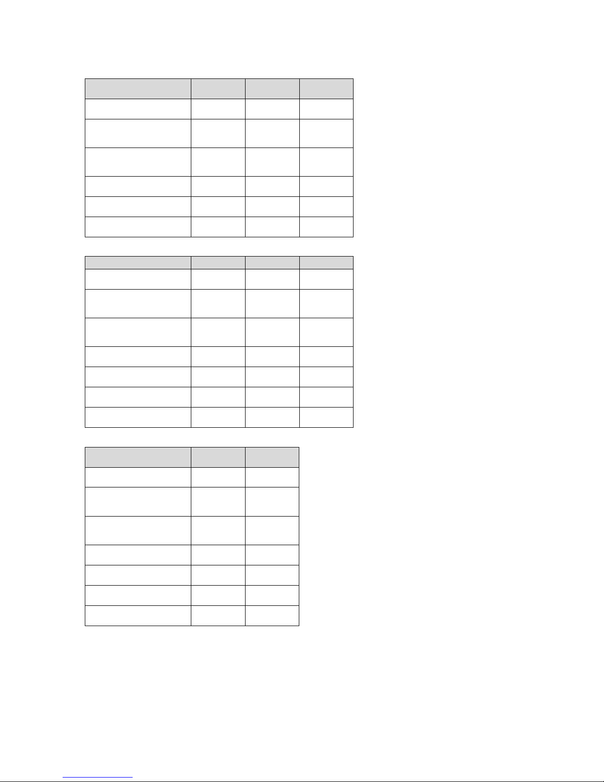
These instructions apply only to:
Product article number
FE 300/3 MR
0010020650
FE 400/3 MR
0010020651
FE 500/3 MR
0010020652
FES 300/3 MR
0010020653
FES 400/3 MR
0010020654
FES 500/3 MR
0010020655
FEW 300/3 MR
0010020656
FEW 400/3 MR
0010020657
FEW 500/3 MR
0010020658
FEWS 400/3 MR
0010020659
FEWS 500/3 MR
0010020660
3 Product description
3.1 Data plate
Explanations for the data plate can be found in the operating
instructions for this product.
3.2 CE label
The CE label shows that the products comply with the basic
requirements of the applicable directives as stated on the
identification plate.
The declaration of conformity can be viewed at the manufacturer's site.
4 Set-up, installation and start-up
You can find more detailed information about set-up, installation and start-up in the enclosed text-free/illustrated installation instructions.
5 Setting the target cylinder
temperature
Danger!
Risk of death from legionella.
Legionella multiply at temperatures below
60 °C.
▶ Ensure that the end user is familiar with
all of the Anti-legionella measures in order
to comply with the applicable regulations
regarding legionella prevention.
1. Set the target cylinder temperature.
– Water temperature: ≥ 60 ℃
2. Check the water hardness.
Water hardness: > 3.57 mol/m³
▶ Soften the water.
3. Check the conductivity of the water.
Conductivity at 20 °C between: 100 … 1,250 µS/cm
▶ Take measures to protect against corrosion.
4. Observe the applicable regulations regarding legionella
prevention.
6 Handing over to the operator
1. Teach the end user how to handle the installation. Answer any questions the operator may have. In particular, draw attention to the safety information which the
operator must follow.
2. Explain to the operator how the safety devices work and
where they are located.
3. Inform the end user that they must have the product
maintained in accordance with the specified intervals.
4. Provide the operator with all relevant instructions and
unit documentation for safe-keeping.
5. Inform the end user about the ways to limit the domestic
hot water outlet temperature so that scalding can be
prevented.
6. Inform the end user about the legionella protection
measures that have been taken.
7 Troubleshooting
7.1 Detecting and rectifying faults
▶ If problems occur whilst operating the product, check
certain points with the aid of the table in the appendix.
Detecting and eliminating faults (→ Page 6)

Decommissioning 8
0020246836_02 Installation instructions 5
7.2 Procuring spare parts
The original components of the product were also certified
by the manufacturer as part of the declaration of conformity.
If you use other, non-certified or unauthorised parts during
maintenance or repair work, this may void the conformity of
the product and it will therefore no longer comply with the
applicable standards.
We strongly recommend that you use original spare parts
from the manufacturer as this guarantees fault-free and safe
operation of the product. To receive information about the
available original spare parts, contact the contact address
provided on the reverse of these instructions.
▶ If you require spare parts for maintenance or repair
work, use only the spare parts that are permitted for the
product.
8 Decommissioning
1. Disconnect the power supply, if required.
2. Close all of the isolators fitted on-site.
3. Drain the cylinder (→ installation instructions).
4. Disconnect the connection cables.
5. Remove the cylinder and correctly dispose of the indi-
vidual components (→ installation instructions).
9 Recycling and disposal
Disposing of the packaging
▶ Dispose of the packaging correctly.
▶ Observe all relevant regulations.
10 Customer service
The contact details for our customer service are provided in
the appendix or on our website.
Appendix
6 Installation instructions 0020246836_02
Appendix
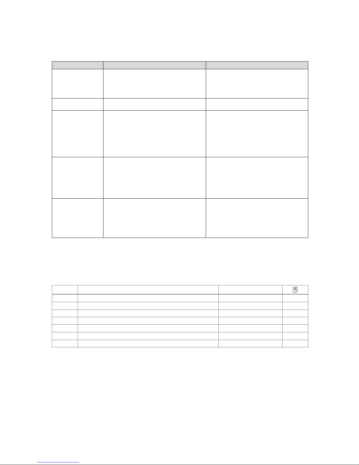
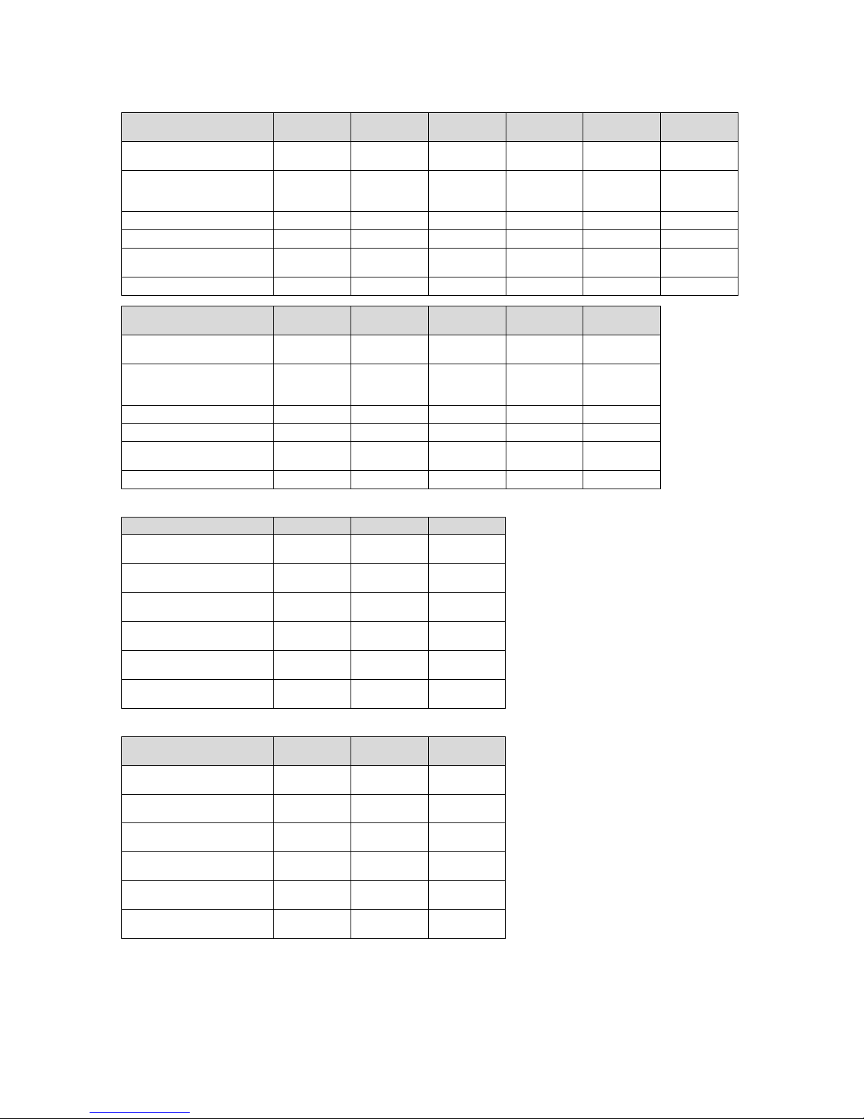
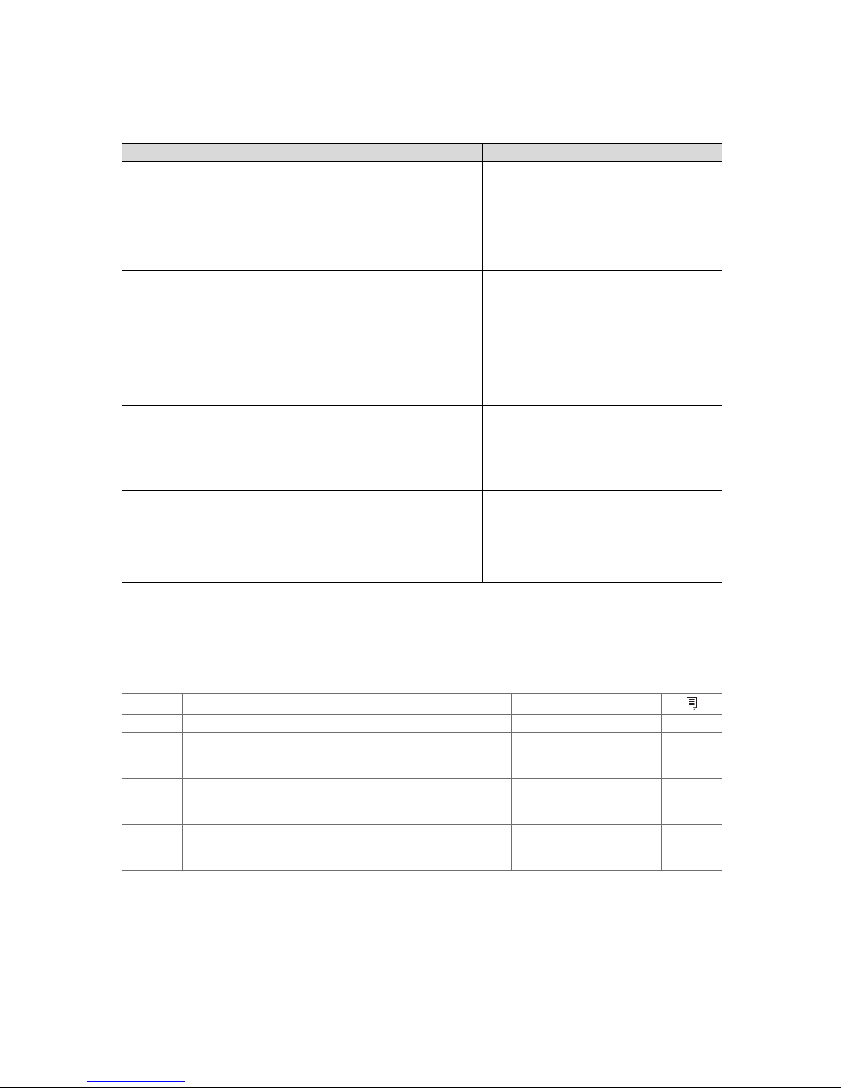
A Detecting and eliminating faults
Fault Possible cause Remedy
No flow rate at the water
tap
1. The cold-water isolation valve is closed.
2. The main filter is blocked.
3. The pressure reducer is not installed correctly.
1. Check and open the cold-water isolation valve.
2. Close the cold-water isolation valve, and clean
the filter and the pressure reducer.
3. Check whether the pressure reducer has been
installed correctly.
Low flow rate and pressure at a water tap
1. The filter in the cold water pipe is clogged. 1. Close the cold-water isolation valve, and clean
the pressure reducer filter.
Water from the water tap
is cold
1. The cylinder was not started up.
2. The cold-water isolation valve is not fully open.
3. The heat generator is not operating.
4. The thermal cut-out for a system component
has been triggered.
5. The 2-port motorised valve is defective.
6. The immersion heater is defective.
1. Open all of the relevant valves.
2. Check the thermostat or the room thermostat
and, if required, set this.
3. Check the heat generator to see if a fault code
is present.
4. Check and initialise the cylinder.
5. Check the connections for the 2-port motorised
valve.
Domestic hot water
temperature at the water
tap too high
1. The thermostat is set too high.
2. The thermostatic valve is not present or is
defective.
1. Check the target temperature. It must be
between 60 and 65 °C.
2. Install a mixer tap.
3. Check the cabling. Repair the cable.
4. Reduce the temperature of the thermostat to
60 °C.
5. Replace the thermostatic valve.
Irregular domestic hot
water output at the water
tap
1. The expansion vessel is defective.
2. The thermal cut-out for a system component
has been triggered (thermal control).
1. Compare the temperature between the controls. The maximum temperature has priority.
2. If required, adjust the pre-charge pressure.
3. Interrupt the power supply to the product and
the heat generator. Check the thermal cut-outs
for the system components and replace these
in the event of a defect.
B Inspection and maintenance work – Overview
The table below lists the manufacturer requirements with respect to minimum inspection and maintenance intervals. If national regulations and directives require shorter inspection and maintenance intervals, you should observe these instead of
the intervals listed.
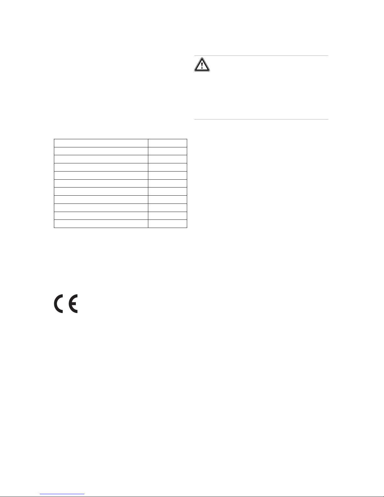
# Maintenance work Interval
1 Check the connections for tightness (visual inspection). Annually
2 Check the temperature and pressure relief valve (by actuating it) Annually
3 Check the pressure in the expansion vessel (annual manometer). Annually
4 Check the tightness of the flange in the cleaning eye (visual inspection) Annually
5 Check the state of wear of the magnesium protection anode Annually
6 Clean the cylinder Annually
7 Check the contacts of the external current anode for corrosion Annually
Appendix
0020246836_02 Installation instructions 7
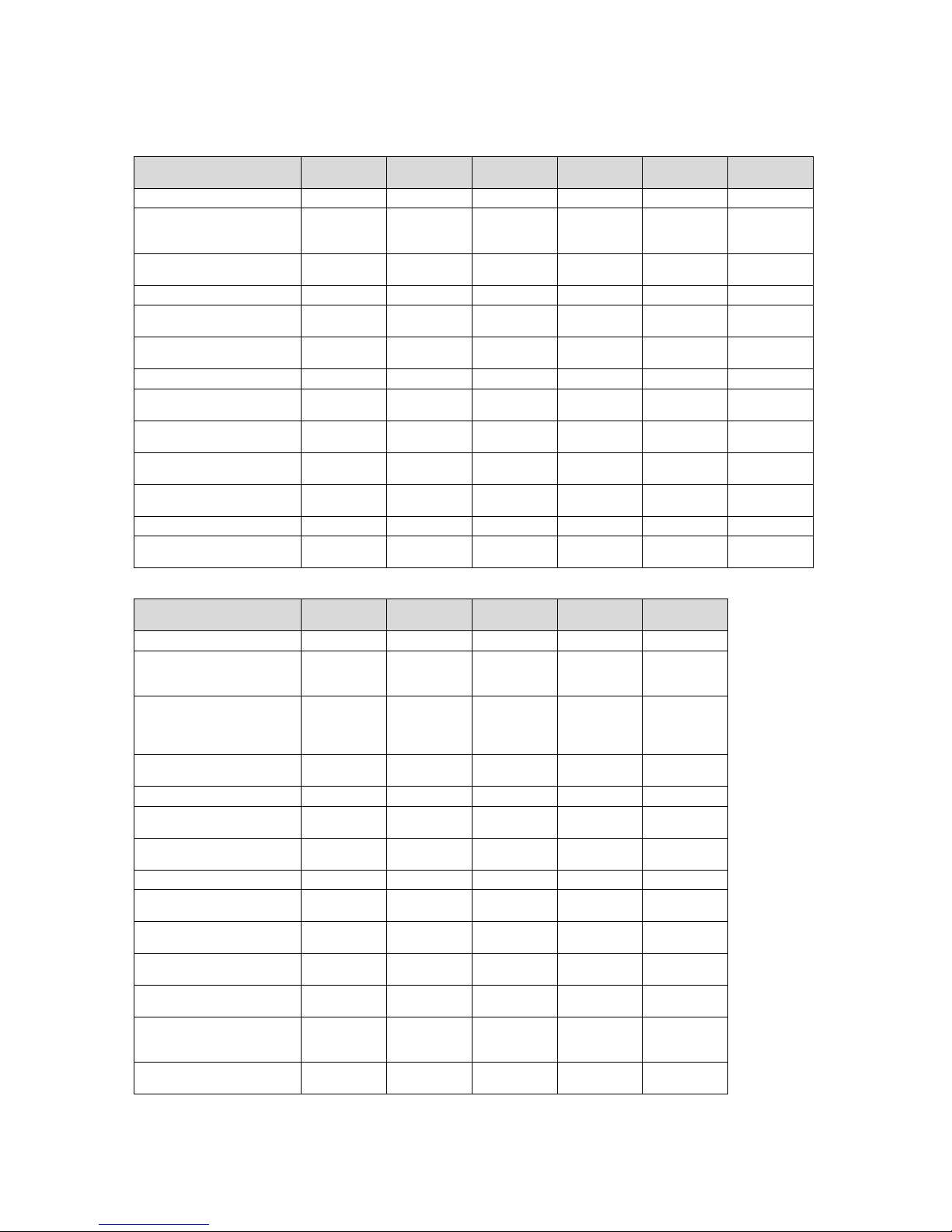
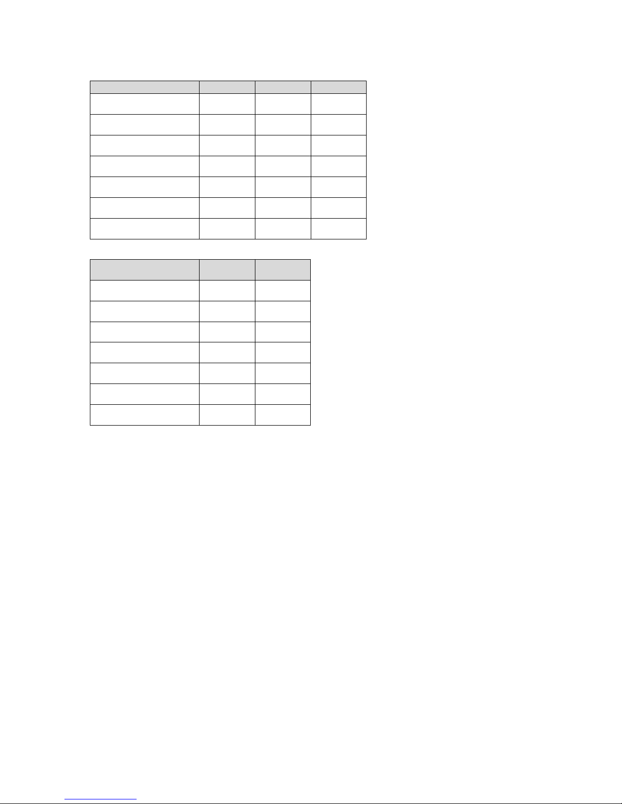
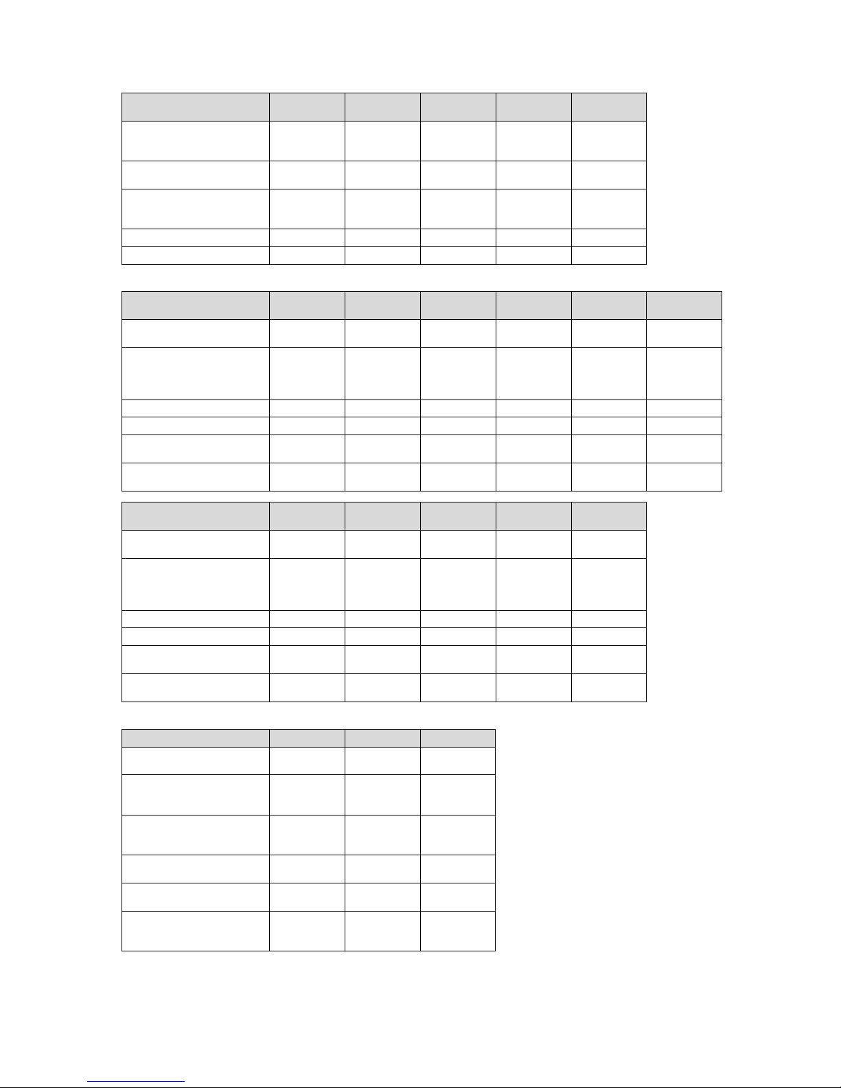
C Technical data
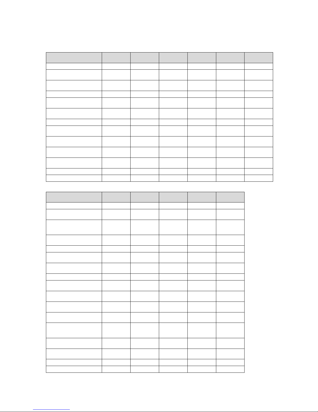
Technical data – FE/FEW general
FE 300/3 MR FE 400/3 MR FE 500/3 MR FEW 300/3MRFEW 400/3MRFEW 500/3
MR
Nominal capacity
294 l 398 l 490 l 281 l 375 l 460 l
Domestic hot water capacity of the heating coil in the
heating circuit
9.9 l 10.9 l 15.2 l 20.4 l 28.9 l 38.6 l
Maximum pressure of the
heating coil during operation
1 MPa 1 MPa 1 MPa 1 MPa 1 MPa 1 MPa
Operating pressure
1 MPa 1 MPa 1 MPa 1 MPa 1 MPa 1 MPa
Maximum temperature of the
heating circuit
110 ℃ 110 ℃ 110 ℃ 110 ℃ 110 ℃ 110 ℃
Maximum hot water temperature
85 ℃ 85 ℃ 85 ℃ 85 ℃ 85 ℃ 85 ℃
Energy efficiency class
B B B B B B
Standby energy consumption
per 24 hrs
1.40 kWh 1.52 kWh 1.78 kWh 1.40 kWh 1.54 kWh 1.84 kWh
Heating coil pressure loss
(heating circuit)
0.0058 MPa 0.0066 MPa 0.00162 MPa 0.00106 MPa 0.0056 MPa 0.00117 MPa
Heating coil surface (heating
circuit)
1.5 m² 1.7 m² 2.3 m² 3.1 m² 4.4 m² 5.9 m²
Volume of mixing water at
40 °C (V40) (heating circuit)
473 l 578 l 742 l 423 l 577 l 710 l
Net weight
103 kg 136 kg 170 kg 141 kg 181 kg 235 kg
Weight filled ready for operation
397 kg 535 kg 661 kg 422 kg 556 kg 694 kg
Technical data – FES/FEWS general
FES 300/3 MR FES 400/3 MR FES 500/3 MR FEWS 400/3MRFEWS 500/3
MR
Nominal capacity
287 l 392 l 481 l 372 l 456 l
Domestic hot water capacity of the heating coil in the
heating circuit
5.4 l 8.5 l 8.5 l 21.2 l 28.9 l
Heat transfer fluid capacity
of the heat exchanger for
the solar circuit/environment
circuit
9.9 l 8.7 l 15.2 l 9.6 l 13.5 l
Maximum pressure of the
heating coil during operation
1 MPa 1 MPa 1 MPa 1 MPa 1 MPa
Operating pressure
1 MPa 1 MPa 1 MPa 1 MPa 1 MPa
Maximum temperature of the
heating circuit
110 ℃ 110 ℃ 110 ℃ 110 ℃ 110 ℃
Maximum hot water temperature
85 ℃ 85 ℃ 85 ℃ 85 ℃ 85 ℃
Energy efficiency class
B B B B B
Standby energy consumption
per 24 hrs
1.40 kWh 1.54 kWh 1.84 kWh 1.58 kWh 1.85 kWh
Heating coil pressure loss
(heating circuit)
0.0017 MPa 0.0022 MPa 0.0024 MPa 0.0026 MPa 0.0057 MPa
Heating coil surface (heating
circuit)
0.8 m² 1.0 m² 1.0 m² 3.2 m² 4.4 m²
Volume of mixing water at
40 °C (V40) (heating circuit)
174 l 287 l 290 l 386 l 471 l
Heating coil pressure loss
(solar circuit/environment
circuit)
0.0058 MPa 0.0066 MPa 0.00183 MPa 0.0021 MPa 0.0027 MPa
Heating coil surface (solar
circuit)
1.5 m² 1.3 m² 2.3 m² 1.5 m² 2.1 m²
Appendix
8 Installation instructions 0020246836_02
FES 300/3 MR FES 400/3 MR FES 500/3 MR FEWS 400/3MRFEWS 500/3
MR
Volume of mixing water at
40 °C (V40) (solar circuit)
468 l 617 l 756 l 606 l 771 l
Net weight
121 kg 147 kg 184 kg 189 kg 249 kg
Weight filled ready for operation
409 kg 540 kg 666 kg 561 kg 703 kg
Technical data – Material
FE 300/3 MR FE 400/3 MR FE 500/3 MR FEW 300/3MRFEW 400/3MRFEW 500/3
MR
Cylinder material
Black steel
(S235JR)
Black steel
(S235JR)
Black steel
(S235JR)
Black steel
(S235JR)
Black steel
(S235JR)
Black steel
(S235JR)
Corrosion protection
Enamel with
magnesium
protection anode
Enamel with
magnesium
protection anode
Enamel with
magnesium
protection anode
Enamel with
magnesium
protection anode
Enamel with
magnesium
protection anode
Enamel with
magnesium
protection
anode
Insulating material
Polyurethane Polyurethane Polyurethane Polyurethane Polyurethane Polyurethane
Thick insulating material
75 mm 70 mm 70 mm 75 mm 70 mm 70 mm
Propellant for insulating material
HFO1233zd(E)
HFO1233zd(E)
HFO1233zd(E)
HFO1233zd(E)
HFO1233zd(E)
HFO1233zd(E)
Ozone depletion potential
ODP
WP 1 WP 1 WP 1 WP 1 WP 1 WP 1
FES 300/3 MR FES 400/3 MR FES 500/3 MR FEWS 400/3MRFEWS 500/3
MR
Cylinder material
Black steel
(S235JR)
Black steel
(S235JR)
Black steel
(S235JR)
Black steel
(S235JR)
Black steel
(S235JR)
Corrosion protection
Enamel with
magnesium
protection anode
Enamel with
magnesium
protection anode
Enamel with
magnesium
protection anode
Enamel with
magnesium
protection anode
Enamel with
magnesium
protection
anode
Insulating material
Polyurethane Polyurethane Polyurethane Polyurethane Polyurethane
Thick insulating material
75 mm 70 mm 70 mm 70 mm 70 mm
Propellant for insulating material
HFO1233zd(E)
HFO1233zd(E)
HFO1233zd(E)
HFO1233zd(E)
HFO1233zd(E)
Ozone depletion potential
ODP
WP 1 WP 1 WP 1 WP 1 WP 1
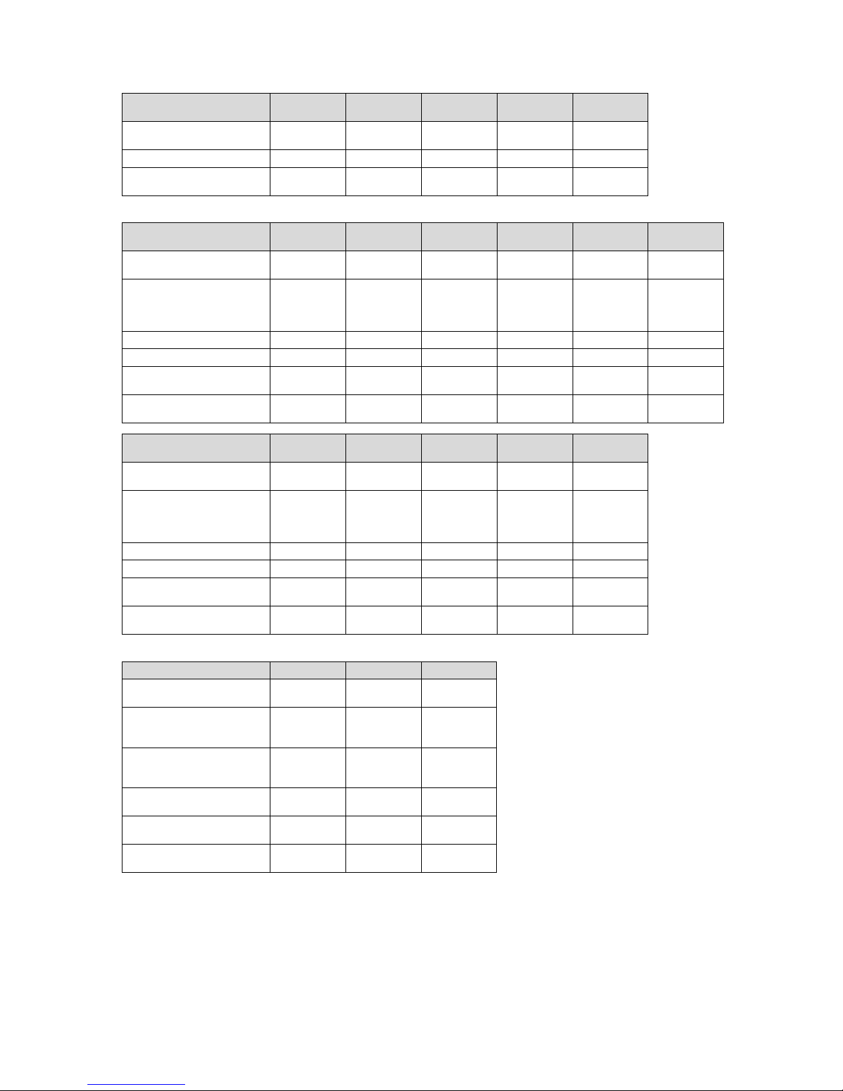
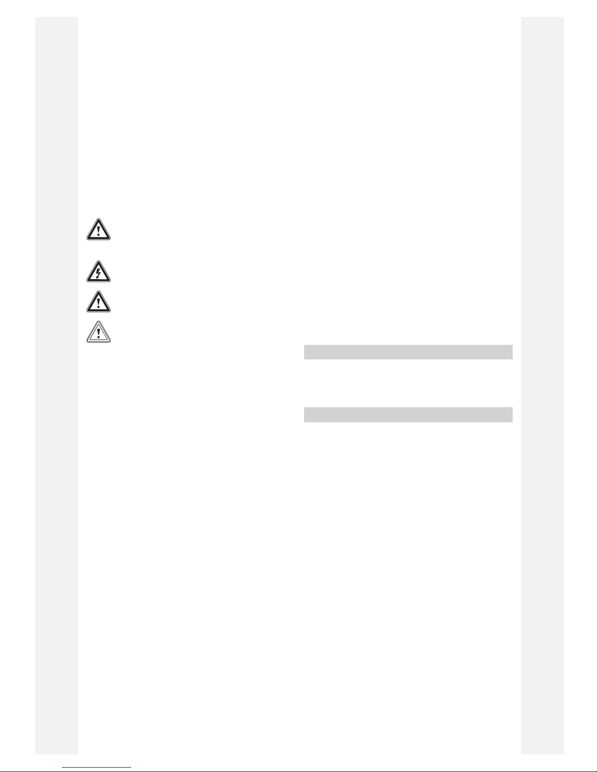
Technical data – FE output
FE 300/3 MR FE 400/3 MR FE 500/3 MR
Output characteristic figure
NL (60 °C)
9.0 15.0 21.0
Continuous domestic hot
water output (heating circuit)
(60 °C 35 K)
24.8 kW 27.1 kW 38.0 kW
Continuous domestic hot
water output (heating circuit)
(60 °C 35 K)
611 l/h 668 l/h 936 l/h
Domestic hot water output
(60 °C)
396 l/10 min 517 l/10 min 623 l/10 min
Specific flow rate Delta
(60 °C 30 K)
46.2 l/min 60.3 l/min 72.7 l/min
Nominal heating medium
volume flow (heating circuit)
1.81 m³/h 1.93 m³/h 2.79 m³/h
Appendix
0020246836_02 Installation instructions 9
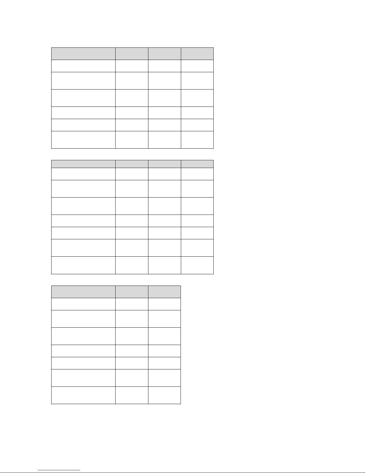
Technical data – FEW output
FEW 300/3MRFEW 400/3MRFEW 500/3
MR
Output characteristic figure
NL (60 °C)
3.8 6.1 8.9
Continuous domestic hot
water output (heating circuit)
(60 °C 35 K)
43.2 kW 62.2 kW 83.0 kW
Continuous domestic hot
water output (heating circuit)
(60 °C 35 K)
1,063 l/h 1,531 l/h 2,041 l/h
Domestic hot water output
(60 °C)
377 l/10 min 504 l/10 min 618 l/10 min
Specific flow rate Delta
(60 °C 30 K)
44.0 l/min 58.8 l/min 72.1 l/min
Nominal heating medium
volume flow (heating circuit)
1.72 m³/h 2.58 m³/h 3.44 m³/h
Technical data – FES output
FES 300/3 MR FES 400/3 MR FES 500/3 MR
Output characteristic figure
NL (60 °C)
1.3 2.6 2.6
Continuous domestic hot
water output (heating circuit)
(60 °C 35 K)
13.5 kW 16.4 kW 16.4 kW
Continuous domestic hot
water output (heating circuit)
(60 °C 35 K)
331 l/h 404 l/h 404 l/h
Domestic hot water output
(60 °C)
161 l/10 min 219 l/10 min 223 l/10 min
Specific flow rate Delta
(60 °C 30 K)
18.8 l/min 25.6 l/min 26.0 l/min
Nominal heating medium
volume flow (heating circuit)
0.99 m³/h 1.20 m³/h 1.20 m³/h
Nominal heating medium
volume flow (solar circuit)
1.81 m³/h 1.93 m³/h 2.79 m³/h
Technical data – FEWS output
FEWS 400/3MRFEWS 500/3
MR
Output characteristic figure
NL (60 °C)
1.5 2.8
Continuous domestic hot
water output (heating circuit)
(60 °C 35 K)
44.3 kW 62.2 kW
Continuous domestic hot
water output (heating circuit)
(60 °C 35 K)
1,091 l/h 1,530 l/h
Domestic hot water output
(60 °C)
266 l/10 min 330 l/10 min
Specific flow rate Delta
(60 °C 30 K)
31.0 l/min 38.5 l/min
Nominal heating medium
volume flow (heating circuit)
1.70 m³/h 2.60 m³/h
Nominal heating medium
volume flow (solar circuit)
2.00 m³/h 2.00 m³/h

Inhalt
10 Installationsanleitung 0020246836_02
Installationsanleitung
Inhalt
1 Sicherheit ........................................................... 11
1.1 Handlungsbezogene Warnhinweise .................... 11
1.2 Bestimmungsgemäße Verwendung .................... 11
1.3 Allgemeine Sicherheitshinweise .......................... 11
1.4 Vorschriften (Richtlinien, Gesetze, Normen) ....... 12
2 Hinweise zur Dokumentation............................ 13
2.1 Mitgeltende Unterlagen beachten........................ 13
2.2 Unterlagen aufbewahren ..................................... 13
2.3 Gültigkeit der Anleitung........................................ 13
3 Produktbeschreibung........................................ 13
3.1 Typenschild.......................................................... 13
3.2 CE-Kennzeichnung.............................................. 13
4 Montage, Installation und Inbetriebnahme ..... 13
5 Speichersolltemperatur einstellen................... 13
6 Übergabe an den Betreiber............................... 13
7 Störungsbehebung............................................ 13
7.1 Störungen erkennen und beheben ...................... 13
7.2 Ersatzteile beschaffen ......................................... 14
8 Außerbetriebnahme........................................... 14
9 Recycling und Entsorgung ............................... 14
10 Kundendienst..................................................... 14
Anhang ............................................................................... 15
A Störungen erkennen und beheben .................. 15
B Inspektions- und Wartungsarbeiten –
Übersicht ............................................................ 15
C Technische Daten.............................................. 16
Sicherheit 1
0020246836_02 Installationsanleitung 11
1 Sicherheit
1.1 Handlungsbezogene Warnhinweise
Klassifizierung der handlungsbezogenen
Warnhinweise
Die handlungsbezogenen Warnhinweise sind
wie folgt mit Warnzeichen und Signalwörtern hinsichtlich der Schwere der möglichen
Gefahr abgestuft:
Warnzeichen und Signalwörter
Gefahr!
Unmittelbare Lebensgefahr oder
Gefahr schwerer Personenschäden
Gefahr!
Lebensgefahr durch Stromschlag
Warnung!
Gefahr leichter Personenschäden
Vorsicht!
Risiko von Sachschäden oder Schäden für die Umwelt
1.2 Bestimmungsgemäße Verwendung
Bei unsachgemäßer oder nicht bestimmungsgemäßer Verwendung können Gefahren für
Leib und Leben des Benutzers oder Dritter
bzw. Beeinträchtigungen des Produkts und
anderer Sachwerte entstehen.
Der Warmwasserspeicher ist dafür bestimmt,
bis maximal 85 °C erwärmtes Trinkwasser in
Haushalten und Gewerbebetrieben zur Verwendung bereit zu halten. Das Produkt ist
dafür bestimmt, in eine Zentralheizungsanlage integriert zu werden. Es ist für die Kombination mit Wärmeerzeugern vorgesehen,
deren Leistung in den Grenzen liegt, die in
den Technischen Daten angegeben sind. Zur
Regelung der Warmwasserbereitung können
witterungsgeführte Regler sowie Regelungen
von geeigneten Wärmeerzeugern verwendet
werden. Das sind Wärmeerzeuger, die eine
Speicherladung vorsehen und über die Anschlussfähigkeit für einen Temperaturfühler
verfügen.
Die bestimmungsgemäße Verwendung beinhaltet:
– das Beachten der beiliegenden Betriebs-,
Installations- und Wartungsanleitungen
des Produkts sowie aller weiteren Komponenten der Anlage
– die Installation und Montage entsprechend
der Produkt- und Systemzulassung
– die Einhaltung aller in den Anleitungen auf-
geführten Inspektions- und Wartungsbedingungen.
Die bestimmungsgemäße Verwendung umfasst außerdem die Installation gemäß IPCode.
Eine andere Verwendung als die in der vorliegenden Anleitung beschriebene oder eine
Verwendung, die über die hier beschriebene
hinausgeht, gilt als nicht bestimmungsgemäß. Nicht bestimmungsgemäß ist
auch jede unmittelbare kommerzielle und
industrielle Verwendung.
Achtung!
Jede missbräuchliche Verwendung ist untersagt.
1.3 Allgemeine Sicherheitshinweise
1.3.1 Gefahr durch unzureichende
Qualifikation
Gültigkeit: Nicht für Russland
Folgende Arbeiten dürfen nur Fachhandwerker durchführen, die hinreichend dafür
qualifiziert sind:
Gültigkeit: Russland
Folgende Arbeiten dürfen nur durch den Hersteller zertifizierte Fachhandwerker durchführen, die hinreichend dafür qualifiziert sind:
– Montage
– Demontage
– Installation
– Inbetriebnahme
– Inspektion und Wartung
– Reparatur
– Außerbetriebnahme
▶ Beachten Sie alle produktbegleitenden
Anleitungen.
▶ Gehen Sie gemäß dem aktuellen Stand
der Technik vor.
▶ Halten Sie alle einschlägigen Richtlinien,
Normen, Gesetze und anderen Vorschriften ein.

1 Sicherheit
12 Installationsanleitung 0020246836_02
1.3.2 Lebensgefahr durch Stromschlag
Wenn Sie spannungsführende Komponenten
berühren, dann besteht Lebensgefahr durch
Stromschlag.
Bevor Sie am Produkt arbeiten:
▶ Ziehen Sie den Netzstecker.
▶ Oder schalten Sie das Produkt spannungs-
frei, indem Sie alle Stromversorgungen
abschalten (elektrische Trennvorrichtung
mit mindestens 3 mm Kontaktöffnung, z. B.
Sicherung oder Leitungsschutzschalter).
▶ Sichern Sie gegen Wiedereinschalten.
▶ Warten Sie mindestens 3 min, bis sich die
Kondensatoren entladen haben.
▶ Prüfen Sie auf Spannungsfreiheit.
1.3.3 Lebensgefahr durch fehlende
Sicherheitseinrichtungen
▶ Installieren Sie die notwendigen Sicher-
heitseinrichtungen in der Anlage.
1.3.4 Verbrennungs- oder
Verbrühungsgefahr durch heiße
Bauteile
▶ Arbeiten Sie erst dann an den Bauteilen,
wenn sie abgekühlt sind.
1.3.5 Verletzungsgefahr durch hohes
Produktgewicht
▶ Transportieren Sie das Produkt mit min-
destens zwei Personen.
1.3.6 Risiko eines Sachschadens durch
ungeeignetes Werkzeug
▶ Um Schraubverbindungen anzuziehen
oder zu lösen, verwenden Sie fachgerechtes Werkzeug.
1.4 Vorschriften (Richtlinien, Gesetze,
Normen)
▶ Beachten Sie die nationalen Vorschriften,
Normen, Richtlinien und Gesetze.
Hinweise zur Dokumentation 2
0020246836_02 Installationsanleitung 13
2 Hinweise zur Dokumentation
2.1 Mitgeltende Unterlagen beachten
▶ Beachten Sie unbedingt alle Betriebs- und Installations-
anleitungen, die Komponenten der Anlage beiliegen.
2.2 Unterlagen aufbewahren
▶ Geben Sie diese Anleitung sowie alle mitgeltenden
Unterlagen an den Anlagenbetreiber weiter.
2.3 Gültigkeit der Anleitung
Diese Anleitung gilt ausschließlich für:
Produkt - Artikelnummer
FE 300/3 MR
0010020650
FE 400/3 MR
0010020651
FE 500/3 MR
0010020652
FES 300/3 MR
0010020653
FES 400/3 MR
0010020654
FES 500/3 MR
0010020655
FEW 300/3 MR
0010020656
FEW 400/3 MR
0010020657
FEW 500/3 MR
0010020658
FEWS 400/3 MR
0010020659
FEWS 500/3 MR
0010020660
3 Produktbeschreibung
3.1 Typenschild
Die Erläuterungen des Typenschilds finden Sie in der
Betriebsanleitung zu diesem Produkt.
3.2 CE-Kennzeichnung
Mit der CE-Kennzeichnung wird dokumentiert, dass die Produkte gemäß dem Typenschild die grundlegenden Anforderungen der einschlägigen Richtlinien erfüllen.
Die Konformitätserklärung kann beim Hersteller eingesehen
werden.
4 Montage, Installation und
Inbetriebnahme
Details zur Montage, Installation und Inbetriebnahme entnehmen Sie der beiliegenden textlosen/bebilderten Installationsanleitung.
5 Speichersolltemperatur einstellen
Gefahr!
Lebensgefahr durch Legionellen!
Legionellen entwickeln sich bei Temperaturen unter 60 °C.
▶ Sorgen Sie dafür, dass der Betreiber alle
Maßnahmen zum Legionellenschutz
kennt, um die geltenden Vorgaben zur
Legionellenprophylaxe zu erfüllen.
1. Stellen Sie die Speichersolltemperatur ein.
– Wassertemperatur: ≥ 60 ℃
2. Prüfen Sie die Wasserhärte.
Wasserhärte: > 3,57 mol/m³
▶ Enthärten Sie das Wasser.
3. Prüfen Sie die Leitfähigkeit des Wassers.
Leitfähigkeit bei 20 °C zwischen: 100 … 1.250 µS/cm
▶ Treffen Sie Maßnahmen für den Korrosionsschutz.
4. Beachten Sie die geltenden Vorgaben zur Legionellenprophylaxe.
6 Übergabe an den Betreiber
1. Unterrichten Sie den Betreiber über die Handhabung
der Anlage. Beantworten Sie all seine Fragen. Weisen
Sie insb. auf die Sicherheitshinweise hin, die der Betreiber beachten muss.
2. Erklären Sie dem Betreiber Lage und Funktion der
Sicherheitseinrichtungen.
3. Informieren Sie den Betreiber darüber, dass er das Produkt gemäß vorgegebener Intervalle warten lassen
muss.
4. Übergeben Sie dem Betreiber alle für ihn bestimmten
Anleitungen und Gerätepapiere zur Aufbewahrung.
5. Informieren Sie den Betreiber über die Möglichkeiten
die Warmwasser-Auslauftemperatur zu begrenzen,
damit Verbrühungen verhindert werden.
6. Informieren Sie den Betreiber über die getroffenen
Legionellen-Schutzmaßnahmen.
7 Störungsbehebung
7.1 Störungen erkennen und beheben
▶ Wenn sich beim Betrieb des Produkts Probleme ergeben,
dann prüfen Sie bestimmte Punkte mit Hilfe der Tabelle
im Anhang.
Störungen erkennen und beheben (→ Seite 15)

8 Außerbetriebnahme
14 Installationsanleitung 0020246836_02
7.2 Ersatzteile beschaffen
Die Originalbauteile des Produkts sind im Zuge der Konformitätsprüfung durch den Hersteller mitzertifiziert worden.
Wenn Sie bei der Wartung oder Reparatur andere, nicht zertifizierte bzw. nicht zugelassene Teile verwenden, dann kann
das dazu führen, dass die Konformität des Produkts erlischt
und das Produkt daher den geltenden Normen nicht mehr
entspricht.
Wir empfehlen dringend die Verwendung von Originalersatzteilen des Herstellers, da damit ein störungsfreier und sicherer Betrieb des Produkts gewährleistet ist. Um Informationen
über die verfügbaren Originalersatzteile zu erhalten, wenden
Sie sich an die Kontaktadresse, die auf der Rückseite der
vorliegenden Anleitung angegeben ist.
▶ Wenn Sie bei Wartung oder Reparatur Ersatzteile benöti-
gen, dann verwenden Sie ausschließlich für das Produkt
zugelassene Ersatzteile.
8 Außerbetriebnahme
1. Trennen Sie ggf. die Stromversorgung.
2. Schließen Sie alle bauseits vorhandenen Absperreinrichtungen.
3. Entleeren Sie den Speicher (→ Installationsanleitung).
4. Trennen Sie die Anschlussleitungen.
5. Demontieren Sie den Speicher und entsorgen Sie die
einzelnen Komponenten ordnungsgemäß (→ Installationsanleitung).
9 Recycling und Entsorgung
Verpackung entsorgen
▶ Entsorgen Sie die Verpackung ordnungsgemäß.
▶ Beachten Sie alle relevanten Vorschriften.
10 Kundendienst
Die Kontaktdaten unseres Kundendiensts finden Sie im Anhang oder auf unserer Website.

Anhang
0020246836_02 Installationsanleitung 15
Anhang
A Störungen erkennen und beheben
Fehler mögliche Ursache Behebung
Kein Durchfluss am
Wasserhahn
1. Kaltwasser-Absperrventil ist geschlossen.
2. Hauptfilter ist verstopft.
3. Druckminderer ist nicht richtig montiert.
1. Prüfen und öffnen Sie das Kaltwasser-Absperrventil.
2. Schließen Sie das Kaltwasser-Absperrventil,
reinigen Sie den Filter und den Druckminderer.
3. Prüfen Sie, ob der Druckminderer richtig montiert ist.
Geringer Durchfluss
und Druck an einem
Wasserhahn
1. Filter in der Kaltwasserleitung ist zugesetzt. 1. Schließen Sie das Kaltwasser-Absperrventil,
reinigen Sie den Filter des Druckminderers.
Wasser aus dem Wasserhahn ist kalt
1. Der Speicher wurde nicht in Betrieb genom-
men.
2. Kaltwasser-Absperrventil ist nicht ganz geöff-
net.
3. Der Wärmeerzeuger ist nicht in Betrieb.
4. Die Thermosicherung einer Systemkomponente
wurde ausgelöst.
5. Das 2-Wege-Motorventil ist defekt.
6. Der Tauchheizkörper ist defekt.
1. Öffnen Sie alle relevanten Ventile.
2. Prüfen Sie den Thermostat bzw. den Raumthermostat und stellen Sie ihn ein.
3. Prüfen Sie den Wärmeerzeuger, ob ein Fehlercode vorhanden ist.
4. Prüfen und initialisieren Sie den Speicher.
5. Prüfen Sie die Anschlüsse des 2-Wege-Motorventils.
Warmwassertemperatur
am Wasserhahn zu hoch
1. Thermostat ist zu hoch eingestellt.
2. Thermostatventil ist nicht vorhanden oder
defekt.
1. Prüfen Sie die Solltemperatur. Sie muss zwischen 60 und 65 °C liegen.
2. Installieren Sie eine Mischbatterie.
3. Prüfen Sie die Verkabelung. Setzen Sie das
Kabel instand.
4. Verringern Sie die Temperatur des Thermostats auf 60 °C.
5. Tauschen Sie das Thermostatventil aus.
Unregelmäßige Warmwasserleistung am Wasserhahn
1. Ausdehnungsgefäß ist defekt.
2. Thermosicherung einer Systemkomponente
wurde ausgelöst (Thermal Control).
1. Vergleichen Sie die Temperatur zwischen
den Reglern. Die maximale Temperatur hat
Vorrang.
2. Passen Sie ggf. den Vordruck an.
3. Unterbrechen Sie die Stromversorgung des
Produkts und des Wärmeerzeugers. Prüfen Sie
die Thermosicherungen der Systemkomponenten und tauschen Sie sie bei einem Defekt aus.
B Inspektions- und Wartungsarbeiten – Übersicht
Die nachfolgende Tabelle listet die Herstelleranforderungen zu Mindestinspektions- und Wartungsintervallen auf. Wenn nationale Vorschriften und Richtlinien kürzere Inspektions- und Wartungsintervalle fordern, dann halten Sie stattdessen die geforderten Intervalle ein.
# Wartungsarbeit Intervall
1 Prüfen Sie die Anschlüsse auf Dichtheit (Sichtprüfung) Jährlich
2 Prüfen Sie das Temperatur- und Druckbegrenzungsventil (durch Betäti-
gung)
Jährlich
3 Prüfen Sie den Druck im Ausdehnungsgefäß (jährlich Manometer) Jährlich
4 Prüfen Sie den Flansch der Reinigungsöffnung auf Dichtheit (Sichtprü-
fung)
Jährlich
5 Prüfen Sie den Verschleißzustand der Magnesiumschutzanode Jährlich
6 Reinigen Sie den Speicher Jährlich
7 Prüfen Sie die Kontakte der Fremdstromanode auf Korrosion Jährlich
Anhang
16 Installationsanleitung 0020246836_02
C Technische Daten
Technische Daten - Allgemein FE/FEW
FE 300/3 MR FE 400/3 MR FE 500/3 MR FEW 300/3MRFEW 400/3MRFEW 500/3
MR
Nenninhalt
294 l 398 l 490 l 281 l 375 l 460 l
Inhalt Heizwasser der Rohrschlange Heizkreis
9,9 l 10,9 l 15,2 l 20,4 l 28,9 l 38,6 l
Maximaler Druck der Rohrschlange im Betrieb
1 MPa 1 MPa 1 MPa 1 MPa 1 MPa 1 MPa
Betriebsdruck
1 MPa 1 MPa 1 MPa 1 MPa 1 MPa 1 MPa
Maximale Temperatur des
Heizkreises
110 ℃ 110 ℃ 110 ℃ 110 ℃ 110 ℃ 110 ℃
Maximale Warmwassertemperatur
85 ℃ 85 ℃ 85 ℃ 85 ℃ 85 ℃ 85 ℃
Energieeffizienzklasse
B B B B B B
Bereitschaftsenergieverbrauch pro 24h
1,40 kWh 1,52 kWh 1,78 kWh 1,40 kWh 1,54 kWh 1,84 kWh
Druckverlust der
Rohrschlange (Heizkreis)
0,0058 MPa 0,0066 MPa 0,00162 MPa 0,00106 MPa 0,0056 MPa 0,00117 MPa
Oberfläche der Rohrschlange
(Heizkreis)
1,5 m² 1,7 m² 2,3 m² 3,1 m² 4,4 m² 5,9 m²
Volumen des Mischwassers
bei 40 °C (V40) (Heizkreis)
473 l 578 l 742 l 423 l 577 l 710 l
Nettogewicht
103 kg 136 kg 170 kg 141 kg 181 kg 235 kg
Gewicht betriebsbereit gefüllt
397 kg 535 kg 661 kg 422 kg 556 kg 694 kg
Technische Daten - Allgemein FES/FEWS
FES 300/3 MR FES 400/3 MR FES 500/3 MR FEWS 400/3MRFEWS 500/3
MR
Nenninhalt
287 l 392 l 481 l 372 l 456 l
Inhalt Heizwasser der Rohrschlange Heizkreis
5,4 l 8,5 l 8,5 l 21,2 l 28,9 l
Inhalt Wärmeträgerflüssigkeit
des Wärmetauschers Solarkreis/Umweltkreis
9,9 l 8,7 l 15,2 l 9,6 l 13,5 l
Maximaler Druck der Rohrschlange im Betrieb
1 MPa 1 MPa 1 MPa 1 MPa 1 MPa
Betriebsdruck
1 MPa 1 MPa 1 MPa 1 MPa 1 MPa
Maximale Temperatur des
Heizkreises
110 ℃ 110 ℃ 110 ℃ 110 ℃ 110 ℃
Maximale Warmwassertemperatur
85 ℃ 85 ℃ 85 ℃ 85 ℃ 85 ℃
Energieeffizienzklasse
B B B B B
Bereitschaftsenergieverbrauch pro 24h
1,40 kWh 1,54 kWh 1,84 kWh 1,58 kWh 1,85 kWh
Druckverlust der
Rohrschlange (Heizkreis)
0,0017 MPa 0,0022 MPa 0,0024 MPa 0,0026 MPa 0,0057 MPa
Oberfläche der Rohrschlange
(Heizkreis)
0,8 m² 1,0 m² 1,0 m² 3,2 m² 4,4 m²
Volumen des Mischwassers
bei 40 °C (V40) (Heizkreis)
174 l 287 l 290 l 386 l 471 l
Druckverlust der
Rohrschlange (Solarkreis/
Umweltkreis)
0,0058 MPa 0,0066 MPa 0,00183 MPa 0,0021 MPa 0,0027 MPa
Oberfläche der Rohrschlange
(Solarkreis)
1,5 m² 1,3 m² 2,3 m² 1,5 m² 2,1 m²
Volumen des Mischwassers
bei 40 °C (V40) (Solarkreis)
468 l 617 l 756 l 606 l 771 l
Nettogewicht
121 kg 147 kg 184 kg 189 kg 249 kg
Gewicht betriebsbereit gefüllt
409 kg 540 kg 666 kg 561 kg 703 kg
Anhang
0020246836_02 Installationsanleitung 17
Technische Daten - Material
FE 300/3 MR FE 400/3 MR FE 500/3 MR FEW 300/3MRFEW 400/3MRFEW 500/3
MR
Speichermaterial
Schwarzstahl
(S235JR)
Schwarzstahl
(S235JR)
Schwarzstahl
(S235JR)
Schwarzstahl
(S235JR)
Schwarzstahl
(S235JR)
Schwarzstahl
(S235JR)
Korrosionsschutz
Emaille mit
MagnesiumSchutzanode
Emaille mit
MagnesiumSchutzanode
Emaille mit
MagnesiumSchutzanode
Emaille mit
MagnesiumSchutzanode
Emaille mit
MagnesiumSchutzanode
Emaille mit
MagnesiumSchutzanode
Dämmmaterial
Polyurethan Polyurethan Polyurethan Polyurethan Polyurethan Polyurethan
Dicke Dämmmaterial
75 mm 70 mm 70 mm 75 mm 70 mm 70 mm
Treibmittel für Dämmmaterial
HFO1233zd(E)
HFO1233zd(E)
HFO1233zd(E)
HFO1233zd(E)
HFO1233zd(E)
HFO1233zd(E)
Ozonabbaupotential ODP
WP 1 WP 1 WP 1 WP 1 WP 1 WP 1
FES 300/3 MR FES 400/3 MR FES 500/3 MR FEWS 400/3MRFEWS 500/3
MR
Speichermaterial
Schwarzstahl
(S235JR)
Schwarzstahl
(S235JR)
Schwarzstahl
(S235JR)
Schwarzstahl
(S235JR)
Schwarzstahl
(S235JR)
Korrosionsschutz
Emaille mit
MagnesiumSchutzanode
Emaille mit
MagnesiumSchutzanode
Emaille mit
MagnesiumSchutzanode
Emaille mit
MagnesiumSchutzanode
Emaille mit
MagnesiumSchutzanode
Dämmmaterial
Polyurethan Polyurethan Polyurethan Polyurethan Polyurethan
Dicke Dämmmaterial
75 mm 70 mm 70 mm 70 mm 70 mm
Treibmittel für Dämmmaterial
HFO1233zd(E)
HFO1233zd(E)
HFO1233zd(E)
HFO1233zd(E)
HFO1233zd(E)
Ozonabbaupotential ODP
WP 1 WP 1 WP 1 WP 1 WP 1
Technische Daten – Leistung FE
FE 300/3 MR FE 400/3 MR FE 500/3 MR
Leistungskennzahl NL
(60 °C)
9,0 15,0 21,0
Warmwasser-Dauerleistung
(Heizkreis) (60 °C 35 K)
24,8 kW 27,1 kW 38,0 kW
Warmwasser-Dauerleistung
(Heizkreis) (60 °C 35 K)
611 l/h 668 l/h 936 l/h
Warmwasser-Ausgangsleistung (60 °C)
396 l/10 min 517 l/10 min 623 l/10 min
Spezifischer Durchfluss
Delta (60 °C 30 K)
46,2 l/min 60,3 l/min 72,7 l/min
Nenn-Heizmittelvolumenstrom (Heizkreis)
1,81 m³/h 1,93 m³/h 2,79 m³/h
Technische Daten – Leistung FEW
FEW 300/3MRFEW 400/3MRFEW 500/3
MR
Leistungskennzahl NL
(60 °C)
3,8 6,1 8,9
Warmwasser-Dauerleistung
(Heizkreis) (60 °C 35 K)
43,2 kW 62,2 kW 83,0 kW
Warmwasser-Dauerleistung
(Heizkreis) (60 °C 35 K)
1.063 l/h 1.531 l/h 2.041 l/h
Warmwasser-Ausgangsleistung (60 °C)
377 l/10 min 504 l/10 min 618 l/10 min
Spezifischer Durchfluss
Delta (60 °C 30 K)
44,0 l/min 58,8 l/min 72,1 l/min
Nenn-Heizmittelvolumenstrom (Heizkreis)
1,72 m³/h 2,58 m³/h 3,44 m³/h
Anhang
18 Installationsanleitung 0020246836_02
Technische Daten – Leistung FES
FES 300/3 MR FES 400/3 MR FES 500/3 MR
Leistungskennzahl NL
(60 °C)
1,3 2,6 2,6
Warmwasser-Dauerleistung
(Heizkreis) (60 °C 35 K)
13,5 kW 16,4 kW 16,4 kW
Warmwasser-Dauerleistung
(Heizkreis) (60 °C 35 K)
331 l/h 404 l/h 404 l/h
Warmwasser-Ausgangsleistung (60 °C)
161 l/10 min 219 l/10 min 223 l/10 min
Spezifischer Durchfluss
Delta (60 °C 30 K)
18,8 l/min 25,6 l/min 26,0 l/min
Nenn-Heizmittelvolumenstrom (Heizkreis)
0,99 m³/h 1,20 m³/h 1,20 m³/h
Nenn-Heizmittelvolumenstrom (Solarkreis)
1,81 m³/h 1,93 m³/h 2,79 m³/h
Technische Daten – Leistung FEWS
FEWS 400/3MRFEWS 500/3
MR
Leistungskennzahl NL
(60 °C)
1,5 2,8
Warmwasser-Dauerleistung
(Heizkreis) (60 °C 35 K)
44,3 kW 62,2 kW
Warmwasser-Dauerleistung
(Heizkreis) (60 °C 35 K)
1.091 l/h 1.530 l/h
Warmwasser-Ausgangsleistung (60 °C)
266 l/10 min 330 l/10 min
Spezifischer Durchfluss
Delta (60 °C 30 K)
31,0 l/min 38,5 l/min
Nenn-Heizmittelvolumenstrom (Heizkreis)
1,70 m³/h 2,60 m³/h
Nenn-Heizmittelvolumenstrom (Solarkreis)
2,00 m³/h 2,00 m³/h

Contenido
0020246836_02 Instrucciones de instalación 19
Instrucciones de instalación
Contenido
1 Seguridad ........................................................... 20
1.1 Advertencias relativas a la operación .................. 20
1.2 Utilización adecuada............................................ 20
1.3 Información general de seguridad ....................... 20
1.4 Disposiciones (directivas, leyes, normas) ........... 21
2 Observaciones sobre la documentación ........ 22
2.1 Consulta de la documentación adicional ............. 22
2.2 Conservación de la documentación .................... 22
2.3 Validez de las instrucciones ................................ 22
3 Descripción del aparato .................................... 22
3.1 Placa de características....................................... 22
3.2 Homologación CE ................................................ 22
4 Montaje, instalación y puesta en marcha........ 22
5 Ajuste de la temperatura nominal del
acumulador ........................................................ 22
6 Entrega al usuario ............................................. 22
7 Solución de averías ........................................... 23
7.1 Detección y solución de averías .......................... 23
7.2 Adquisición de piezas de repuesto ...................... 23
8 Puesta fuera de servicio ................................... 23
9 Reciclaje y eliminación ..................................... 23
10 Servicio de Asistencia Técnica ........................ 23
Anexo .................................................................................24
A Detección y solución de averías ...................... 24
B Vista general de tareas de revisión y
mantenimiento ................................................... 24
C Datos técnicos ................................................... 25
1 Seguridad
20 Instrucciones de instalación 0020246836_02
1 Seguridad
1.1 Advertencias relativas a la
operación
Clasificación de las advertencias relativas
a la manipulación
Las advertencias relativas a la manipulación
se clasifican con signos de advertencia e indicaciones de aviso de acuerdo con la gravedad de los posibles peligros:
Signos de advertencia e indicaciones de
aviso
Peligro
Peligro de muerte inminente o peligro
de lesiones graves
Peligro
Peligro de muerte por electrocución
Advertencia
peligro de lesiones leves
Atención
Riesgo de daños materiales o daños
al medio ambiente
1.2 Utilización adecuada
Su uso incorrecto o utilización inadecuada
puede dar lugar a situaciones de peligro mortal o de lesiones para el usuario o para terceros, así como provocar daños en el producto
u otros bienes materiales.
El acumulador de agua caliente está destinado a mantener agua potable calentada
hasta un máximo de 85 °C para su uso en
hogares y empresas industriales. El producto
está previsto para integrarse en una instalación de calefacción central. Está concebido
para utilizarse en combinación con generadores de calor cuya potencia se encuentre
dentro de los límites indicados en los datos
técnicos. Para regular la producción de agua
caliente sanitaria pueden emplearse reguladores controlados por sonda exterior, así
como reguladores de generadores de calor
adecuados. Son apropiados aquellos generadores de calor que cuentan con sobrealimentación y con posibilidad de conexión de
un sensor de temperatura.
La utilización adecuada implica:
– Tener en cuenta las instrucciones de fun-
cionamiento, instalación y mantenimiento
del producto y de todos los demás componentes de la instalación.
– Realizar la instalación y el montaje con-
forme a la homologación del producto y
del sistema.
– Cumplir todas las condiciones de inspec-
ción y mantenimiento recogidas en las instrucciones.
La utilización adecuada implica, además,
realizar la instalación conforme al código IP.
Una utilización que no se corresponda con
o que vaya más allá de lo descrito en las
presentes instrucciones se considera inadecuada. También es inadecuado cualquier uso
de carácter directamente comercial o industrial.
¡Atención!
Se prohíbe todo uso abusivo del producto.
1.3 Información general de seguridad
1.3.1 Peligro por cualificación insuficiente
Validez: No aplicable en Rusia
Las siguientes tareas solo deben ser llevadas
a cabo por profesionales autorizados que
estén debidamente cualificados:
Validez: Rusia
Las siguientes tareas solo deben ser llevadas
a cabo por profesionales autorizados que
estén debidamente cualificados:
– Montaje
– Desmontaje
– Instalación
– Puesta en marcha
– Revisión y mantenimiento
– Reparación
– Puesta fuera de servicio
▶ Tenga en cuenta todas las instrucciones
que acompañan al producto.
▶ Proceda según el estado actual de la téc-
nica.
▶ Respete todas las leyes, normas y directi-
vas aplicables.
1.3.2 Peligro de muerte por electrocución
Si toca los componentes conductores de
tensión, existe peligro de descarga eléctrica.

Seguridad 1
0020246836_02 Instrucciones de instalación 21
Antes de realizar cualquier trabajo en el producto:
▶ Retire el enchufe de red.
▶ O deje el producto sin tensión desconec-
tando todos los suministros de corriente
(dispositivo de separación eléctrica con
una abertura de contacto de al menos
3 mm, p. ej., fusibles o disyuntores).
▶ Asegúrelo para impedir que se pueda co-
nectar accidentalmente.
▶ Espere al menos 3 min hasta que los con-
densadores se hayan descargado.
▶ Verifique que no hay tensión.
1.3.3 Peligro de muerte por falta de
dispositivos de seguridad
▶ Monte en la instalación los dispositivos de
seguridad necesarios.
1.3.4 Peligro de quemaduras o
escaldaduras por componentes
calientes
▶ Espere a que estos componentes se ha-
yan enfriado antes de empezar a trabajar.
1.3.5 Peligro de lesiones debido al peso
elevado del producto
▶ Transporte el producto como mínimo entre
dos personas.
1.3.6 Riesgo de daños materiales por el
uso de herramientas inadecuadas
▶ Utilice las herramientas adecuadas para
apretar o aflojar las uniones atornilladas.
1.4 Disposiciones (directivas, leyes,
normas)
▶ Observe las disposiciones, normas, directi-
vas y leyes nacionales.
2 Observaciones sobre la documentación
22 Instrucciones de instalación 0020246836_02
2 Observaciones sobre la
documentación
2.1 Consulta de la documentación adicional
▶ Tenga en cuenta sin excepción todos los manuales de
uso e instalación que acompañan a los componentes de
la instalación.
2.2 Conservación de la documentación
▶ Entregue estas instrucciones y toda la documentación de
validez paralela al usuario de la instalación.
2.3 Validez de las instrucciones
Estas instrucciones son válidas únicamente para:
Aparato - Referencia del artículo
FE 300/3 MR
0010020650
FE 400/3 MR
0010020651
FE 500/3 MR
0010020652
FES 300/3 MR
0010020653
FES 400/3 MR
0010020654
FES 500/3 MR
0010020655
FEW 300/3 MR
0010020656
FEW 400/3 MR
0010020657
FEW 500/3 MR
0010020658
FEWS 400/3 MR
0010020659
FEWS 500/3 MR
0010020660
3 Descripción del aparato
3.1 Placa de características
En las instrucciones de la placa de características puede
consultar la información detallada sobre este producto.
3.2 Homologación CE
Con la homologación CE se certifica que los aparatos cumplen los requisitos básicos de las directivas aplicables conforme figura en la placa de características.
Puede solicitar la declaración de conformidad al fabricante.
4 Montaje, instalación y puesta en
marcha
Puede consultar los detalles relacionados con el montaje,
la instalación y la puesta en marcha en las instrucciones de
instalación sin texto/con imágenes adjuntas.
5 Ajuste de la temperatura nominal del
acumulador
Peligro
Peligro de muerte por legionela.
La legionela se desarrolla a temperaturas por
debajo de 60 °C.
▶ Asegúrese de que el usuario conozca to-
das las medidas de protección contra la
legionela para cumplir las disposiciones
vigentes sobre profilaxis frente a la legionela.
1. Ajuste la temperatura nominal del acumulador.
– Temperatura del agua: ≥ 60 ℃
2. Compruebe la dureza del agua.
Dureza del agua: > 3,57 mol/m³
▶ Descalcifique el agua.
3. Compruebe la conductividad del agua.
Conductividad a 20 °C entre: 100 … 1.250 µS/cm
▶ Adopte medidas de protección contra la corrosión.
4. Tenga en cuenta las indicaciones vigentes sobre la
profilaxis de la legionela.
6 Entrega al usuario
1. Explique al usuario cómo se debe manejar la instalación. Responda a todas sus preguntas. Haga especial
hincapié en aquellas indicaciones de seguridad que el
usuario debe tener en cuenta.
2. Explique al usuario dónde se encuentran y cómo funcionan los dispositivos de seguridad.
3. Señale al usuario la necesidad de respetar los intervalos de mantenimiento prescritos para el aparato.
4. Entregue al usuario todas las instrucciones y documentos del aparato correspondientes para que los guarde.
5. Informe al usuario sobre la posibilidad de limitar la temperatura de salida del agua caliente para evitar que se
produzcan lesiones de quemaduras.
6. Informe al usuario de las medidas de protección contra
legionela adoptadas.

Solución de averías 7
0020246836_02 Instrucciones de instalación 23
7 Solución de averías
7.1 Detección y solución de averías
▶ Si surgen problemas durante el funcionamiento del pro-
ducto, la tabla incluida en el anexo le ayudará a comprobar algunos puntos.
Detección y solución de averías (→ Página 24)
7.2 Adquisición de piezas de repuesto
Los repuestos originales del producto están certificados de
acuerdo con la comprobación de conformidad del fabricante.
Si durante la reparación o el mantenimiento emplea piezas
no certificadas o autorizadas, el certificado de conformidad
del producto perderá su validez y no se corresponderá con
las normas actuales.
Recomendamos encarecidamente la utilización de piezas de
repuesto originales del fabricante, ya que con ello, se garantiza un funcionamiento correcto y seguro del producto. Para
recibir información sobre las piezas de repuesto originales,
diríjase a la dirección de contacto que aparece en la página
trasera de las presentes instrucciones.
▶ Si necesita piezas de repuesto para el mantenimiento o
la reparación, utilice exclusivamente piezas de repuesto
autorizadas.
8 Puesta fuera de servicio
1. Desconecte el suministro eléctrico en caso necesario.
2. Cierre todos los dispositivos de bloqueo que haya instalado el propietario.
3. Vacíe el acumulador (→ Instrucciones de instalación).
4. Desconecte los cables de suministro.
5. Desmonte el acumulador y elimine los distintos componentes de forma adecuada (→ Instrucciones de instalación).
9 Reciclaje y eliminación
Eliminación del embalaje
▶ Elimine el embalaje de forma adecuada.
▶ Se deben tener en cuenta todas las especificaciones
relevantes.
10 Servicio de Asistencia Técnica
Puede encontrar los datos de contacto de nuestro Servicio
de Asistencia Técnica en el anexo o en nuestra página web.
Anexo
24 Instrucciones de instalación 0020246836_02
Anexo
A Detección y solución de averías
Error posible causa Solución
No hay caudal en el grifo 1. La llave de paso de agua fría está cerrada.
2. Filtro principal obstruido.
3. Descompresor mal montado.
1. Compruebe y abra la llave de paso del agua
fría.
2. Cierre la llave de paso de agua fría, limpie el
filtro y el descompresor.
3. Compruebe si el descompresor está montado
correctamente.
Caudal y presión bajos
un grifo
1. El filtro del conducto de agua fría está obstruido.
1. Cierre la llave de paso de agua fría, limpie el
filtro del descompresor.
El agua del grifo está fría 1. El acumulador no se ha puesto en marcha.
2. La llave de paso de agua fría no está completamente abierta.
3. El generador de calor no está en funcionamiento.
4. El fusible térmico de seguridad de un componente del sistema se ha disparado.
5. La válvula motor de dos vías está defectuosa.
6. La resistencia eléctrica de inmersión está
defectuosa.
1. Abra todas las válvulas relevantes.
2. Compruebe el termostato o el termostato de
ambiente y ajústelo.
3. Compruebe el generador de calor, hay un
código de error.
4. Compruebe e inicialice el acumulador.
5. Compruebe las conexiones de la válvula motor
de 2 vías.
Temperatura de agua
caliente sanitaria en el
grifo demasiado alta
1. Termostato ajustado demasiado alto.
2. La válvula termostática no está ajustada o está
defectuosa.
1. Compruebe la temperatura nominal. Debe
encontrarse entre 60 y 65 °C.
2. Instale un grifo mezclador.
3. Compruebe el cableado. Repare el cable.
4. Baje la temperatura del termostato a 60 °C.
5. Sustituya la válvula termostática.
Rendimiento de agua
caliente irregular en el
grifo
1. Vaso de expansión defectuoso.
2. El fusible térmico de seguridad de un componente del sistema se ha disparado (Thermal
Control).
1. Compruebe la temperatura entre los reguladores. La temperatura máxima tiene prioridad.
2. En caso necesario, ajuste la presión previa.
3. Interrumpa el suministro de corriente del producto y del generador de calor. Compruebe el
fusible térmico del componente del sistema y
sustitúyalo si es necesario.
B Vista general de tareas de revisión y mantenimiento
La siguiente tabla recoge los requisitos del fabricante en cuanto a los intervalos mínimos de revisión y mantenimiento. Sin
embargo, en caso de que las normativas y directivas nacionales prescriban intervalos de revisión y mantenimiento más cortos, aténgase a los intervalos exigidos.
# Trabajo de mantenimiento Intervalo
1 Compruebe la estanqueidad de las conexiones (inspección visual) Anual
2 Compruebe la válvula de limitación de temperatura y presión (accionán-
dola)
Anual
3 Compruebe la presión en el vaso de expansión (anualmente manómetro) Anual
4 Compruebe la estanqueidad de la brida de la abertura de inspección (ins-
pección visual)
Anual
5 Compruebe el estado de desgaste del ánodo protector de magnesio Anual
6 Limpie el acumulador Anual
7 Compruebe la posible corrosión de los contactos del ánodo de corriente
externa
Anual

Anexo
0020246836_02 Instrucciones de instalación 25
C Datos técnicos
Datos técnicos: generalidades FE/FEW
FE 300/3 MR FE 400/3 MR FE 500/3 MR FEW 300/3MRFEW 400/3MRFEW 500/3
MR
Contenido nominal
294 l 398 l 490 l 281 l 375 l 460 l
Contenido agua de calefacción del serpentín del circuito de calefacción
9,9 l 10,9 l 15,2 l 20,4 l 28,9 l 38,6 l
Presión máxima del serpentín en funcionamiento
1 MPa 1 MPa 1 MPa 1 MPa 1 MPa 1 MPa
Presión de servicio
1 MPa 1 MPa 1 MPa 1 MPa 1 MPa 1 MPa
Temperatura máxima del circuito de calefacción
110 ℃ 110 ℃ 110 ℃ 110 ℃ 110 ℃ 110 ℃
Temperatura máxima de
agua caliente sanitaria
85 ℃ 85 ℃ 85 ℃ 85 ℃ 85 ℃ 85 ℃
Clase de eficiencia energética
B B B B B B
Consumo de energía en
standby cada 24h
1,40 kWh 1,52 kWh 1,78 kWh 1,40 kWh 1,54 kWh 1,84 kWh
Pérdida de presión del serpentín (circuito de calefacción)
0,0058 MPa 0,0066 MPa 0,00162 MPa 0,00106 MPa 0,0056 MPa 0,00117 MPa
Superficie del serpentín (circuito de calefacción)
1,5 m² 1,7 m² 2,3 m² 3,1 m² 4,4 m² 5,9 m²
Volumen del agua de desagüe combinada a 40 °C (V40)
(circuito de calefacción)
473 l 578 l 742 l 423 l 577 l 710 l
Peso neto
103 kg 136 kg 170 kg 141 kg 181 kg 235 kg
Peso operativo lleno
397 kg 535 kg 661 kg 422 kg 556 kg 694 kg
Datos técnicos: generalidades FES/FEWS
FES 300/3 MR FES 400/3 MR FES 500/3 MR FEWS 400/3MRFEWS 500/3
MR
Contenido nominal
287 l 392 l 481 l 372 l 456 l
Contenido agua de calefacción del serpentín del circuito de calefacción
5,4 l 8,5 l 8,5 l 21,2 l 28,9 l
Contenido de fluido convector del intercambiador de calor circuito solar/círculo ambiental
9,9 l 8,7 l 15,2 l 9,6 l 13,5 l
Presión máxima del serpentín en funcionamiento
1 MPa 1 MPa 1 MPa 1 MPa 1 MPa
Presión de servicio
1 MPa 1 MPa 1 MPa 1 MPa 1 MPa
Temperatura máxima del circuito de calefacción
110 ℃ 110 ℃ 110 ℃ 110 ℃ 110 ℃
Temperatura máxima de
agua caliente sanitaria
85 ℃ 85 ℃ 85 ℃ 85 ℃ 85 ℃
Clase de eficiencia energética
B B B B B
Consumo de energía en
standby cada 24h
1,40 kWh 1,54 kWh 1,84 kWh 1,58 kWh 1,85 kWh
Pérdida de presión del serpentín (circuito de calefacción)
0,0017 MPa 0,0022 MPa 0,0024 MPa 0,0026 MPa 0,0057 MPa
Superficie del serpentín (circuito de calefacción)
0,8 m² 1,0 m² 1,0 m² 3,2 m² 4,4 m²
Volumen del agua de desagüe combinada a 40 °C (V40)
(circuito de calefacción)
174 l 287 l 290 l 386 l 471 l
Anexo
26 Instrucciones de instalación 0020246836_02
FES 300/3 MR FES 400/3 MR FES 500/3 MR FEWS 400/3MRFEWS 500/3
MR
Pérdida de presión del intercambiador de calor (circuito
solar/círculo ambiental)
0,0058 MPa 0,0066 MPa 0,00183 MPa 0,0021 MPa 0,0027 MPa
Superficie del serpentín (circuito solar)
1,5 m² 1,3 m² 2,3 m² 1,5 m² 2,1 m²
Volumen del agua de desagüe combinada a 40 °C (V40)
(circuito solar)
468 l 617 l 756 l 606 l 771 l
Peso neto
121 kg 147 kg 184 kg 189 kg 249 kg
Peso operativo lleno
409 kg 540 kg 666 kg 561 kg 703 kg
Datos técnicos: material
FE 300/3 MR FE 400/3 MR FE 500/3 MR FEW 300/3MRFEW 400/3MRFEW 500/3
MR
Material del acumulador
Acero negro
(S235JR)
Acero negro
(S235JR)
Acero negro
(S235JR)
Acero negro
(S235JR)
Acero negro
(S235JR)
Acero negro
(S235JR)
Protección anticorrosión
Esmaltado
con ánodo de
protección de
magnesio
Esmaltado
con ánodo de
protección de
magnesio
Esmaltado
con ánodo de
protección de
magnesio
Esmaltado
con ánodo de
protección de
magnesio
Esmaltado
con ánodo de
protección de
magnesio
Esmaltado
con ánodo de
protección de
magnesio
Material aislante
Poliuretano Poliuretano Poliuretano Poliuretano Poliuretano Poliuretano
Material aislante grueso
75 mm 70 mm 70 mm 75 mm 70 mm 70 mm
Agente expansor para material aislante
HFO1233zd(E)
HFO1233zd(E)
HFO1233zd(E)
HFO1233zd(E)
HFO1233zd(E)
HFO1233zd(E)
Potencial de agotamiento del
ozono ODP
WP 1 WP 1 WP 1 WP 1 WP 1 WP 1
FES 300/3 MR FES 400/3 MR FES 500/3 MR FEWS 400/3MRFEWS 500/3
MR
Material del acumulador
Acero negro
(S235JR)
Acero negro
(S235JR)
Acero negro
(S235JR)
Acero negro
(S235JR)
Acero negro
(S235JR)
Protección anticorrosión
Esmaltado
con ánodo de
protección de
magnesio
Esmaltado
con ánodo de
protección de
magnesio
Esmaltado
con ánodo de
protección de
magnesio
Esmaltado
con ánodo de
protección de
magnesio
Esmaltado
con ánodo de
protección de
magnesio
Material aislante
Poliuretano Poliuretano Poliuretano Poliuretano Poliuretano
Material aislante grueso
75 mm 70 mm 70 mm 70 mm 70 mm
Agente expansor para material aislante
HFO1233zd(E)
HFO1233zd(E)
HFO1233zd(E)
HFO1233zd(E)
HFO1233zd(E)
Potencial de agotamiento del
ozono ODP
WP 1 WP 1 WP 1 WP 1 WP 1
Datos técnicos: rendimiento FE
FE 300/3 MR FE 400/3 MR FE 500/3 MR
Rendimiento ventilación nominal (60 °C)
9,0 15,0 21,0
Potencia constante del agua
caliente sanitaria (circuito de
calefacción) (60° C 35K)
24,8 kW 27,1 kW 38,0 kW
Potencia constante del agua
caliente sanitaria (circuito de
calefacción) (60° C 35K)
611 l/h 668 l/h 936 l/h
Potencia de salida del agua
caliente sanitaria (60 °C)
396 l/10 min 517 l/10 min 623 l/10 min
Flujo específico Delta (60 °C
30 K)
46,2 l/min 60,3 l/min 72,7 l/min
Flujo volumétrico nominal
del agente calorífico (circuito
de calefacción)
1,81 m³/h 1,93 m³/h 2,79 m³/h
Anexo
0020246836_02 Instrucciones de instalación 27
Datos técnicos: rendimiento FEW
FEW 300/3MRFEW 400/3MRFEW 500/3
MR
Rendimiento ventilación nominal (60 °C)
3,8 6,1 8,9
Potencia constante del agua
caliente sanitaria (circuito de
calefacción) (60° C 35K)
43,2 kW 62,2 kW 83,0 kW
Potencia constante del agua
caliente sanitaria (circuito de
calefacción) (60° C 35K)
1.063 l/h 1.531 l/h 2.041 l/h
Potencia de salida del agua
caliente sanitaria (60 °C)
377 l/10 min 504 l/10 min 618 l/10 min
Flujo específico Delta (60 °C
30 K)
44,0 l/min 58,8 l/min 72,1 l/min
Flujo volumétrico nominal
del agente calorífico (circuito
de calefacción)
1,72 m³/h 2,58 m³/h 3,44 m³/h
Datos técnicos: rendimiento FES
FES 300/3 MR FES 400/3 MR FES 500/3 MR
Rendimiento ventilación nominal (60 °C)
1,3 2,6 2,6
Potencia constante del agua
caliente sanitaria (circuito de
calefacción) (60° C 35K)
13,5 kW 16,4 kW 16,4 kW
Potencia constante del agua
caliente sanitaria (circuito de
calefacción) (60° C 35K)
331 l/h 404 l/h 404 l/h
Potencia de salida del agua
caliente sanitaria (60 °C)
161 l/10 min 219 l/10 min 223 l/10 min
Flujo específico Delta (60 °C
30 K)
18,8 l/min 25,6 l/min 26,0 l/min
Flujo volumétrico nominal
del agente calorífico (circuito
de calefacción)
0,99 m³/h 1,20 m³/h 1,20 m³/h
Flujo volumétrico nominal
del agente calorífico (circuito
solar)
1,81 m³/h 1,93 m³/h 2,79 m³/h
Datos técnicos: rendimiento FEWS
FEWS 400/3MRFEWS 500/3
MR
Rendimiento ventilación nominal (60 °C)
1,5 2,8
Potencia constante del agua
caliente sanitaria (circuito de
calefacción) (60° C 35K)
44,3 kW 62,2 kW
Potencia constante del agua
caliente sanitaria (circuito de
calefacción) (60° C 35K)
1.091 l/h 1.530 l/h
Potencia de salida del agua
caliente sanitaria (60 °C)
266 l/10 min 330 l/10 min
Flujo específico Delta (60 °C
30 K)
31,0 l/min 38,5 l/min
Flujo volumétrico nominal
del agente calorífico (circuito
de calefacción)
1,70 m³/h 2,60 m³/h
Flujo volumétrico nominal
del agente calorífico (circuito
solar)
2,00 m³/h 2,00 m³/h

Sommaire
28 Notice d’installation 0020246836_02
Notice d’installation
Sommaire
1 Sécurité............................................................... 29
1.1 Mises en garde relatives aux opérations ............. 29
1.2 Utilisation conforme ............................................. 29
1.3 Consignes générales de sécurité ........................ 29
1.4 Prescriptions (directives, lois, normes) ................ 30
2 Remarques relatives à la documentation........ 31
2.1 Respect des documents complémentaires
applicables........................................................... 31
2.2 Conservation des documents .............................. 31
2.3 Validité de la notice.............................................. 31
3 Description du produit ...................................... 31
3.1 Plaque signalétique ............................................. 31
3.2 Marquage CE....................................................... 31
4 Montage, installation et mise en
fonctionnement.................................................. 31
5 Réglage de la température de consigne du
ballon .................................................................. 31
6 Remise à l’utilisateur......................................... 31
7 Dépannage ......................................................... 32
7.1 Identification et élimination des dérangements .... 32
7.2 Approvisionnement en pièces de rechange ........ 32
8 Mise hors service............................................... 32
9 Recyclage et mise au rebut .............................. 32
10 Service après-vente........................................... 32
Annexe ...............................................................................33
A Identification et élimination des
dérangements .................................................... 33
B Travaux d’inspection et de maintenance –
vue d’ensemble.................................................. 33
C Caractéristiques techniques ............................ 34
 Loading...