

Page 1
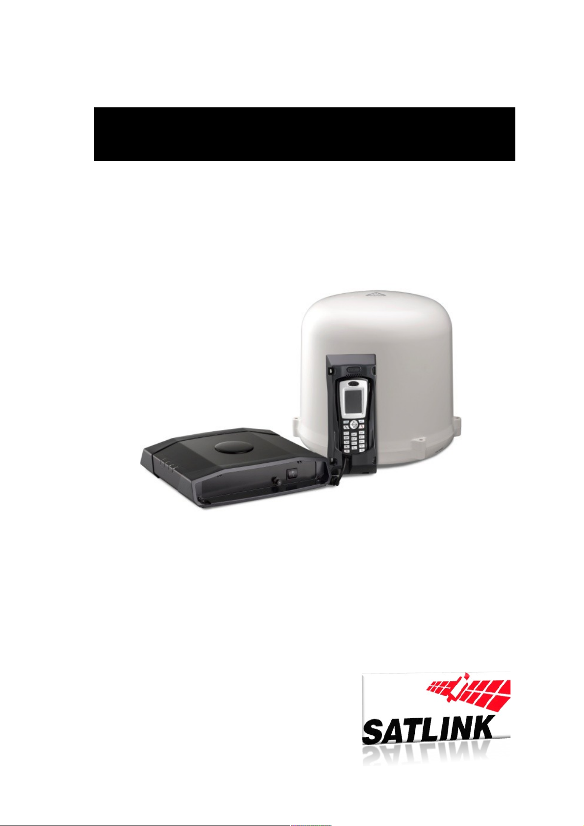
FB250 INSTALLATION MANUAL
Page 2
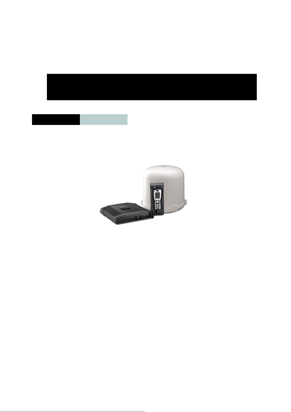
The FB250 User Equipment (UE) is a maritime broadband system, providing
simultaneous high-speed data and voice communication via satellite through the
Inmarsat FleetBroadband system
Applications include:
Internet browsing
E-mail
Phone and fax services
Large file transfers
Video conferencing and Streaming
Features and interfaces
The FB250 FleetBroadband UE offers the following features and interfaces:
Simultaneous voice and data communication over FleetBroadband
Full duplex, single or multi-user, up to 284 kbps
Support for streaming IP at: 32, 64, 128 kbps
Installation of Satlink Maritime
1 General
Page 3
Standard Voice (AMBE+2, 4.0 kbps)
Fax/High Quality Voice (64kbps, A-law PCM)
4 LAN ports [with 2 ports supporting Power over Ethernet (PoE)] for computers,
routers, access points, IP handsets etc.
2 Standard RJ11 Phone/Fax ports for standard phones, fax machines or analog
modems
Expansion slot (supporting 1 voice port and 1 LAN port)
Built-in Web Console allowing you to manage your phone book, messages and calls,
and customize the terminal to your specific needs
Input power: 10.5 V - 32 V DC (14 A - 5.5 A)
CE certified
FCC certified
Operation at high temperatures
Do not touch areas of the User Equipment (UE) that are marked with this symbol when
operating very high ambient temperatures.
Installed the UE in a location where unintentional contact can be avoided if the ambient
temperature may rise above 55°C. The UE can be placed in a accessible area if the maximum
ambient temperature does not exceed 55°C.
For more information on installation, refer to the installation section of the FB250 User
Equipment User’s Guide.
Throughout the document where references are made to products or part numbers then these
part numbers are as well valid when contacting Satlink.
READ THIS MANU A L CAREFULLY !
Warranty will be void if guidelines are not followed.
When installing a Maritime FBB 250 unit on a vessel the following important guidelines must
be followed in order to ensure that the antennas will operate trouble free throughout its
service life.
Page 4
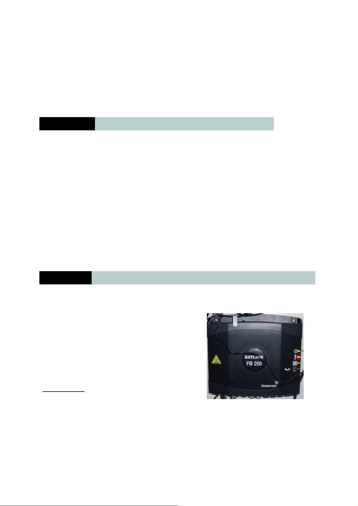
1 This kit include:
On this Satlink FB 250 Equipment you can find next on the package:
1.- Satlink FB 250 Antenna (Satlink Ref: )
2.- Satlink BDU 250 Unit (Satlink Ref: )
3.- Primary Handset and Cradle (Satlink Ref: )
4.- Power cable (Satlink Ref: )
5- Antena Coaxial Cable ((Satlink Ref: )
6.- User Manual
7.- Installation Manual
8.- Quick User Guide
9.- LAN Cable
10.- Support Cable for GPS or Service
2 FB250 System Units
1.- The Satlink FB250 System is base on:
a. Main Unit (BDU= Below Deck Unit)
BDU can be place in wall or desktop installation, you
should be care about power and ventilation
requirements.
Power supply
The voltage range is 10.5 - 32 VDC; 14A - 5.5A. It is
recommended that the voltage is provided by the 24 VDC power bus on the ship. Be aware of
high start-up peak current: 20A @ 24V, 5ms.
If a 24 VDC power bus is not available, an external 115/230 VAC to 24 VDC power supply
can be used.
Page 5
Equipment ventilation
To ensure adequate cooling of the terminal, 5cm of unobstructed space must be maintained
around all sides of the unit (except the bottom side).
The ambient temperature range of the terminal is: -25°C to +55°C.
Do not operate in an explosive atmosphere.
Do not operate the equipment in the presence of flammable gases or fumes.
Operation of any electrical equipment in such an environment constitutes a definite safety
hazard.
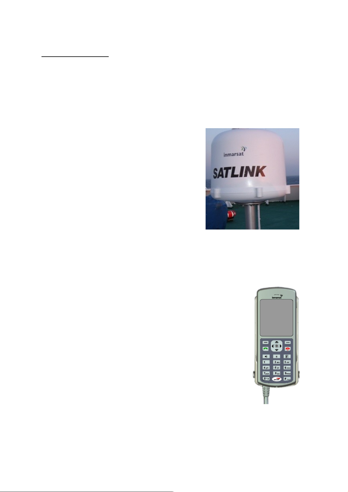
b. Antenna Unit (ADU Above Deck Unit)
The FB250 FleetBroadband antenna system is a
FleetBroadband Class 9 system, based on 3 axes.
Communication between BDU and ADU is through a simple
coaxial cable. Inside the Antenna we can find a GPS antenna,
RF unit and unit boards for communication and stabilized the
antenna.
c. Primary Handset + Cradle
The Satlink FB250 has a dedicated RJ-45 port for connecting the
Primary Handset, this is a special RJ-45 port to communicate the BDU
with the Handset.
Handset is based on:
• Exclusive design
• Color screen
• Send SMS from Handset
• Languages: Spanish & English
• Weight: 80 gr
• Size: 14 x 6 x 3 cm
d. Powering and Antenna Cables
The equipment is shipped with all necessary cables to start up the system.
It is provide with:
- 1 Power Cable (3 meters)
o 1 Pair consists of Red (Positive) and Black (Negative)
Page 6
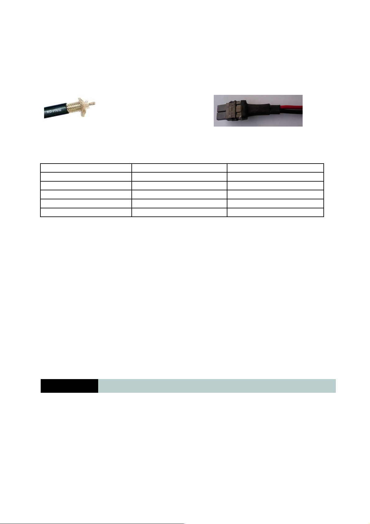
o 12 AWG Wire:
- 1 Antenna Cable (22-meter RG 214/U Type terminated with both N (male)
connectors)
Specification on coaxial cable for another distance:
Antenna Cable Type Max Cable Length (m) Loss @ 1.6GHz (dB/100m)
Huber+Suhner RG223/U 18 60.5
Huber+Shuner RG214 34 32.9
Belden RG8/U 50 19.1
SSB-Electronic Ecoflex 15 80 13.1
Huber+Suhner S10162B11 90 12.0
Grounding, cables and connections
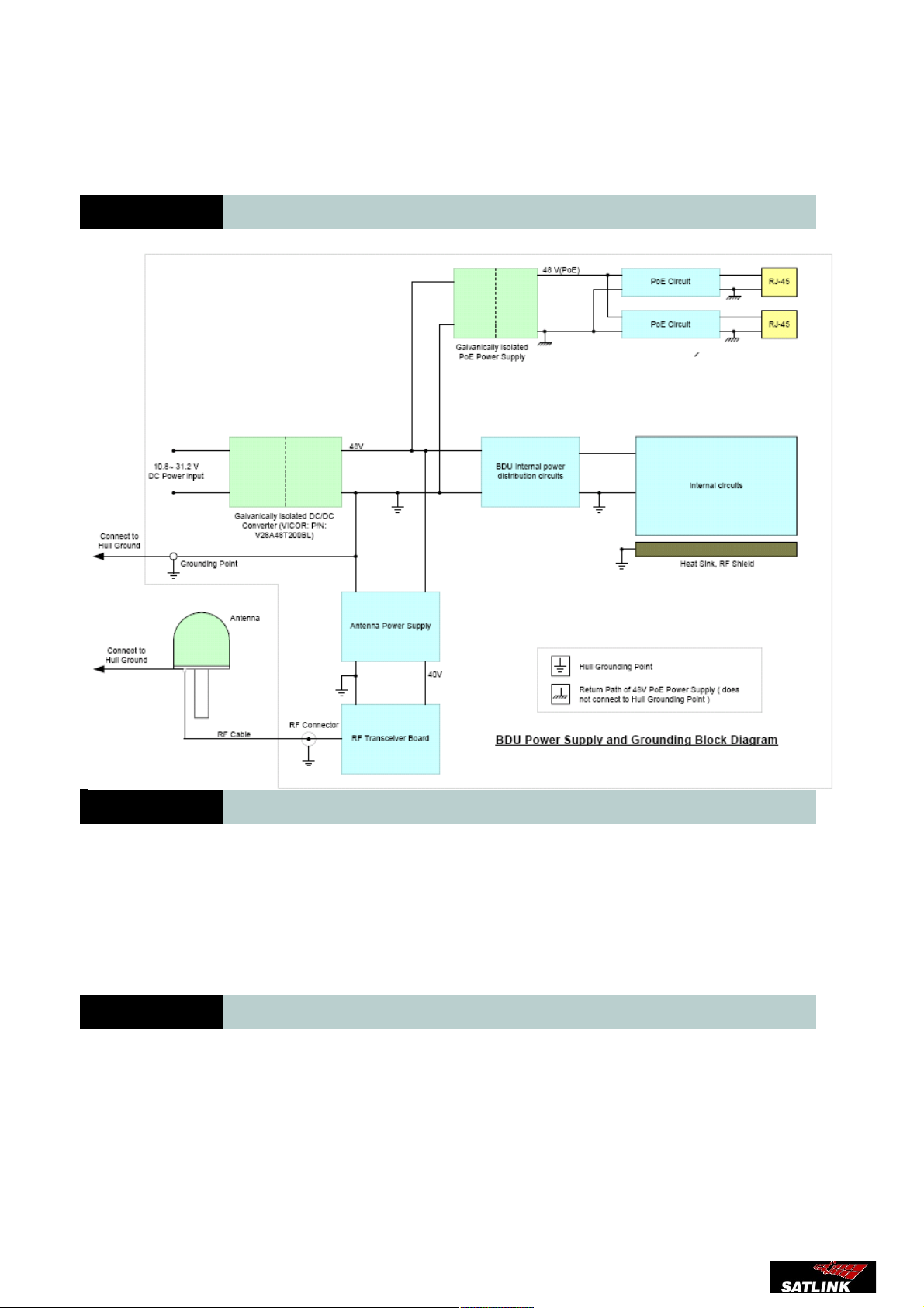
To minimize shock hazard, the equipment chassis and cabinet must be connected to an
electrical ground. Both terminal and antenna must be grounded to the ship. For further
grounding information refers to the Installation manual.
Do not extend the cables beyond the lengths specified for the equipment.
The cable between the terminal and antenna can be extended if it complies with the specified
data concerning cable losses etc.
All cables for the FB250 FleetBroadband system are shielded and should not be affected by
magnetic fields. However, try to avoid running cables parallel to AC wiring as it might cause
malfunction of the equipment.
3 Installation Guide ANTENNA (ADU)
Installation of the 3 axis antenna on a post is done according to Annex A. The diameter of the
post shall preferably be between 35 and 50 mm using the standard clamp supplied in the kit.
Annex A is self explaining. Notice the TORQUES for bolts and nuts.
A small loop should be made on the coax cable near to the plug SPAC M00233 in order to be
able to pull the cable about 15 cm up through the Mounting Pole, when the antenna is
installed or removed.
Page 7

If a long (e.g. 3m) post is used onboard a ship it is recommended that this is fastened to the
ship using standard clamps rather than welding. This will enable the post to be laid down in
case removal of the antenna is required.
3.1 Characteristics of “Pole Mount Kit”
The installation is based on a “Pole Mount Kit” supplied by Satlink. Installation using the
“Pole Mount Kit” is shown in Annex A.
The kit consists of the following components and can be purchased from Satlink:
1) 1pcs. Mounting Pole, Part No. SPAC-M00423
2) 1pcs. Rubber Gasket, Part No. SPAC-M00425
3) 6pcs. Plastic Bushings, Part No. SPAC-M00227
4) 6pcs. Washer, Part No. SPAC-M90-10062
5) 6pcs. Screw, Part No. SPAC-M90-10102
6) 2pcs. Clamp, Part No. SPAC-M00428
7) 2pcs. Clamp, Part No. SPAC-M00429
8) 8pcs. Nuts M8, Part No. SPAC-M90-10105
9) 2pcs. Flange, Part No. SPAC-M00430
10) 1pcs. Plug for Mounting Pole, Part No. SPAC-M00233
11) 1pcs. Screw M5*10, Part No. SPAC-M90-10104
These components are shipped in one separate box. The installer, upon receipt of a box is
required to check the content.
Functionality of the components:
1) Mounting Pole Part No. SPAC-M00424 is a piece of standard tube with a mounting
flange welded onto it. The component is made from a stainless steel alloy that is easy to
cut, machine and weld. It is part of the ventilating system for the dome. The standard
length is 400mm and must not be shortened in maritime application.
2) Rubber Gasket, Part No. SPAC-M00425 is used to ensure that water or dust does not
enter into the area around the centre hole in the bottom of the dome. The centre hole is
part of the ventilating system for the dome and MUST NOT BE BLOCKED. Also the
gasket will protect the N-type connector from water and dust and hence ensure long life
time.
3) Bushings, Part No. SPAC-M00227 are used to ensure NO electric contact between the
mechanical parts of the antenna (in the dome) and the Mounting Pole. This isolation is not
required in vehicle installations but is required in maritime installations, where the
antenna and coaxial cable to the antenna must be isolated from ships structure in order to
avoid any circulating DC current that could cause uncontrolled corrosion.
Page 8

4) Washers, Part No. SPAC-M90-10062 are used to protect the plastic bushings SPAC-
M00227 when the screws SPAC-M90-10102 are tightened to the specified torque (refer to
Annex A). The washers MUST be used.
5) Screws, Part No. SPAC-M90-10102 are M6 (metric), 25mm long screws made from
stainless steel (A4) are used for fastening the antenna to the flange on the Mounting Pole
so that the installation will endure vibrations and heavy loads due to wind or surges from
rough sea. DO NOT CHANGE THE LENGTH OF THE SCREWS.
6) Clamps, Part No. SPAC-M00428 are used to fasten the flanges SPAC-M00430 to the
Mounting Pole, refer to Annex A.
7) Clamps, Part No. SPAC-M00429 are used to fasten the Mounting Pole to any post
with a diameter between 35 and 50 mm, refer to Annex A.
8) Nuts, Part No. SPAC-M90-10105 are M8 nut used for the clamps, refer to Annex A.
Nuts are to be tightened to 5Nm.
9) Flange, Part No. SPAC-M00430 are used for linking the clamp holding forces.
10) Plug, Part No. SPAC-M00233 is used for partly closing the bottom of the Mounting
Pole so that no surge of water will fill the tube or damage any part of the antenna. Any
condensing water within the antenna and/or tube will drop out by the plug. The plug will
also prevent the coaxial cable from vibrating in the tube.
11) Screw, M5*10, Part No. SPAC-M90-10104 is used to secure the plug.
The kit offers the following advantages:
1. Flexible and ease of installation with no or little preceding work e.g. on board a
vessel.
2. Ventilation of the antenna and at the same time makes it comply with its relevant
IP class.
3. Protects the coaxial cable going to the antenna and its N-type connector.
4. Isolating the antenna from the structure on which it is installed, this is a must in
maritime installations where no DC-current is allowed to circulate in any part of ships
body.
3.2 Vibration Conditions
The antennas (2-and 3 axis versions) are designed to meet the following operating vibration
levels in any of 3 perpendicular directions measured at the mounting base of the radome i.e. at
the flange of the standard Mounting Pole described above:
Random Vibration 1.05 Grms with the following spectral density
Page 9
5-20 Hz………….0.02G2/Hz
20-150 Hz……….-3dB/octave
And further,
Single Frequency Vibration 5-10 Hz with amplitude 2.54 mm
10-15 Hz with amplitude 0.76mm
15-25 Hz with amplitude 0.40mm
25-33 Hz with amplitude 0.23mm
Vibration levels in a typical installation are usually much less than to the above mentioned
values. It is however the responsibility of the installer to verify, that the cited levels are not
exceeded in any mode of operation of the vehicle/vessel. In case of abnormal vibration,
typically at a resonance frequency, measures much be taken in order to displace the resonance
frequency or to dampen the vibration amplitude.
3.3 Alternative installation kits
Satlink can assist in designing alternative Mounting Kits in case it should be needed e.g. in
places where space is limited. Any new design should take into consideration the functional
requirements listed in 2.
3.4 Installation Details
Installation of ADU with antenna cable
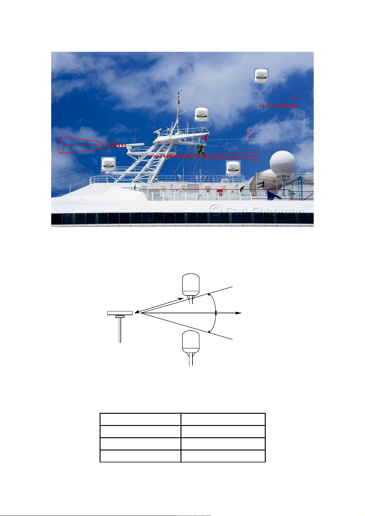
The location of the ADU has to be kept away from the beam width of any search or
tracking radar, which transmits radiating power, and HF/ VHF radiating antennas;
safety compass distance is also to be take into account
Page 10
Important notes to be followed before installing ADU
The following notes shall be observed:
1. The location of the ADU has to be kept away from the beam width of any
search or tracking radar, which transits radiating power.
With reference to the illustration, there are recommended mounting positions of the
ADU where they are kept away from the red region area of the beam width. This way,
the ADU will not be interfered by any transmitting radar. The angle of radar beam
width normally ranges from 10º to 25º degrees with respect to the centre of the radar
arm. However, it is worthwhile to check its manufacture’s technical specification.
Radar Power Operation Damage
0 - 10 kW d = 5 m d = 2 m
10 - 30 kW d = 9 m d = 4 m
30 - 50 kW d = 12 m d = 5 m
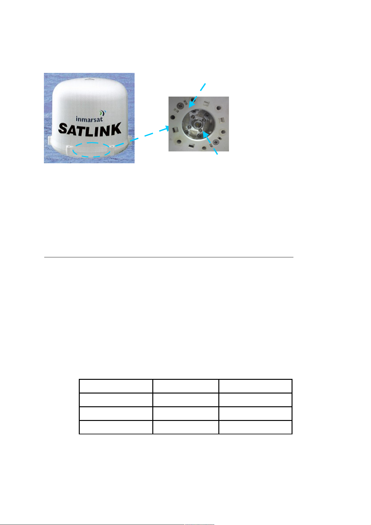
ADU Mounting Base
N-Type Receptacle
Page 11
15°
15°
R A D A R
d
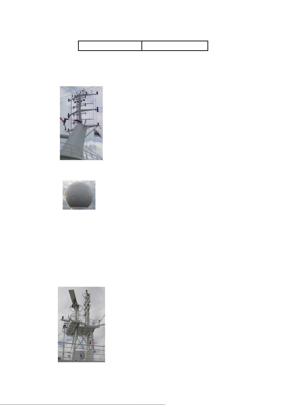
2. The line of sight to satellites of the ADU shall not be obstructed by any large
obstacle in a vessel or ship. This will result in the degradation of the satellite
signal. Examples of the large obstacles are as follow:
Size (diameter) Distance (minimum)
16 cm 3 m
26 cm 5 m
52 cm 10 m
Position 2
Recommended positions
of ADU
Radar Beam Width
Position 1
Position 3
Page 12
104 cm 20 m
• Upper deck of ship and ship’s funnels
• VSAT
• Large mechanical structure mounting of any radar
Page 13
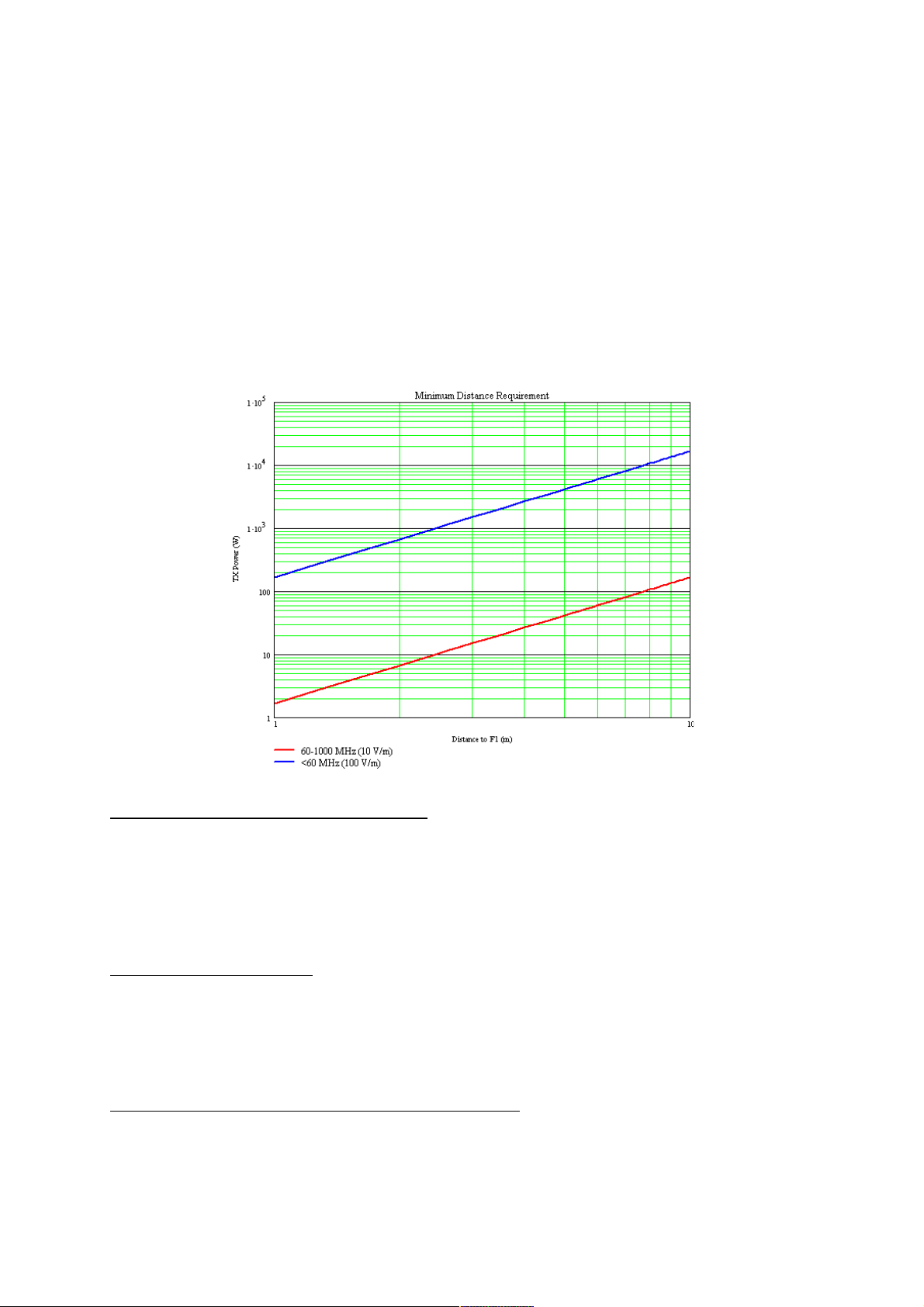
3. For the safety reason, all personnel has to keep away at least 1-meter from
the ADU.
On the FB250 FleetBroadband System, the minimum safety distance on the focal
line to the antenna panel is 0.6m, based on a radiation level of 10 W/m2. The
radiation level is 100 W/m2 at a distance of 0.2m from the antenna panel.
4. The antenna must be installed as far away as possible from ship’s radio
antennas
Connecting Antenna Cable
There is a coaxial connector at the base centre of the ADU where it is a N-type
receptacle connector. The antenna cable terminated with N-type plug connector is to
be inserted into the ADU first before proceeding to the installation of the ADU.
Mounting of ADU
The mounting of the ADU depends on the structure of the vessel or ship. It can be
mounted on either on long post or antenna mast (if available on the ship) as long as it
is ship’s vibration free.
Mounting of ADU on Antenna Mast
The requirements of the antenna mast are as follow:
Page 14
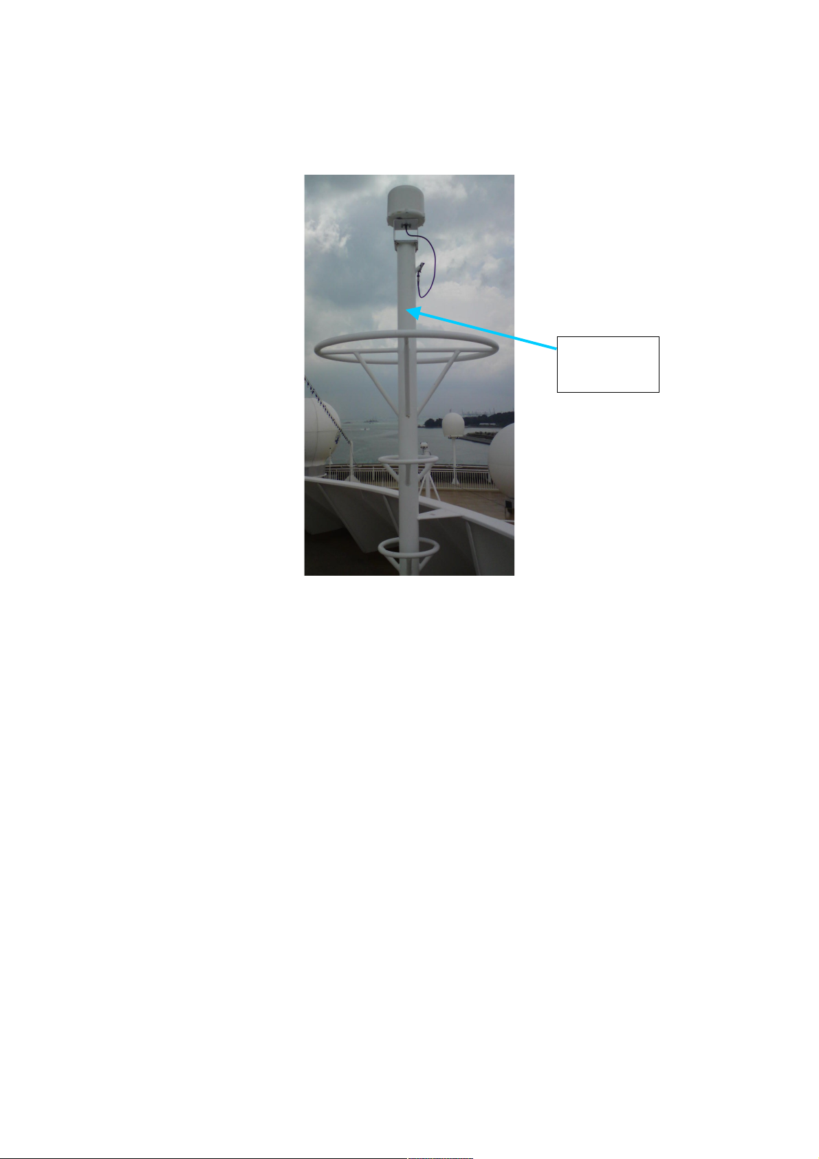
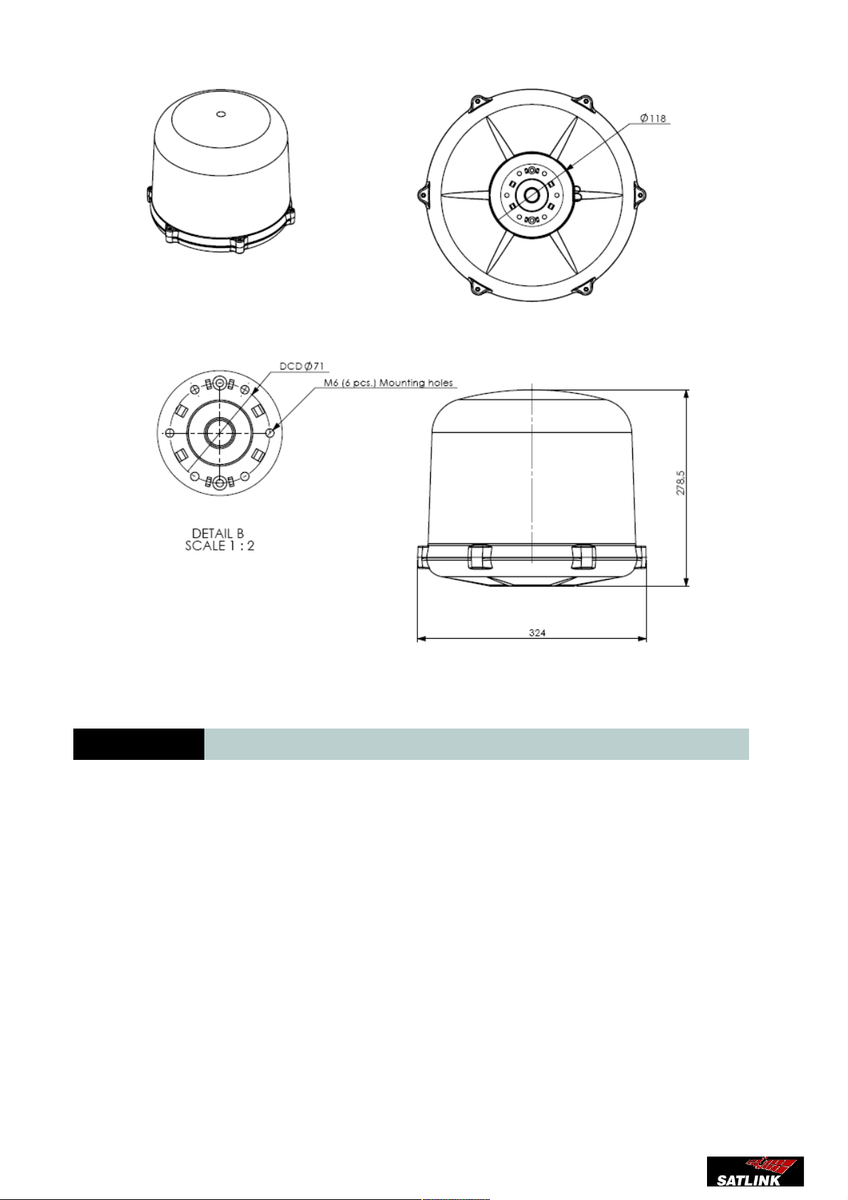
• The physical size of the mast shall support the weight of ADU at 3.8kg and
the physical dimension of Ø319.5mm with height of 277mm. An example of the
antenna mast is illustrated as below.
• The mast should provide the internal hole for the installation of the antenna
cable
• The flange (known as the top plate) of the mast shall meet the dimensions
of the ADU’s mounting base, where there are 6 holes.
Antenna
Mast
Page 15
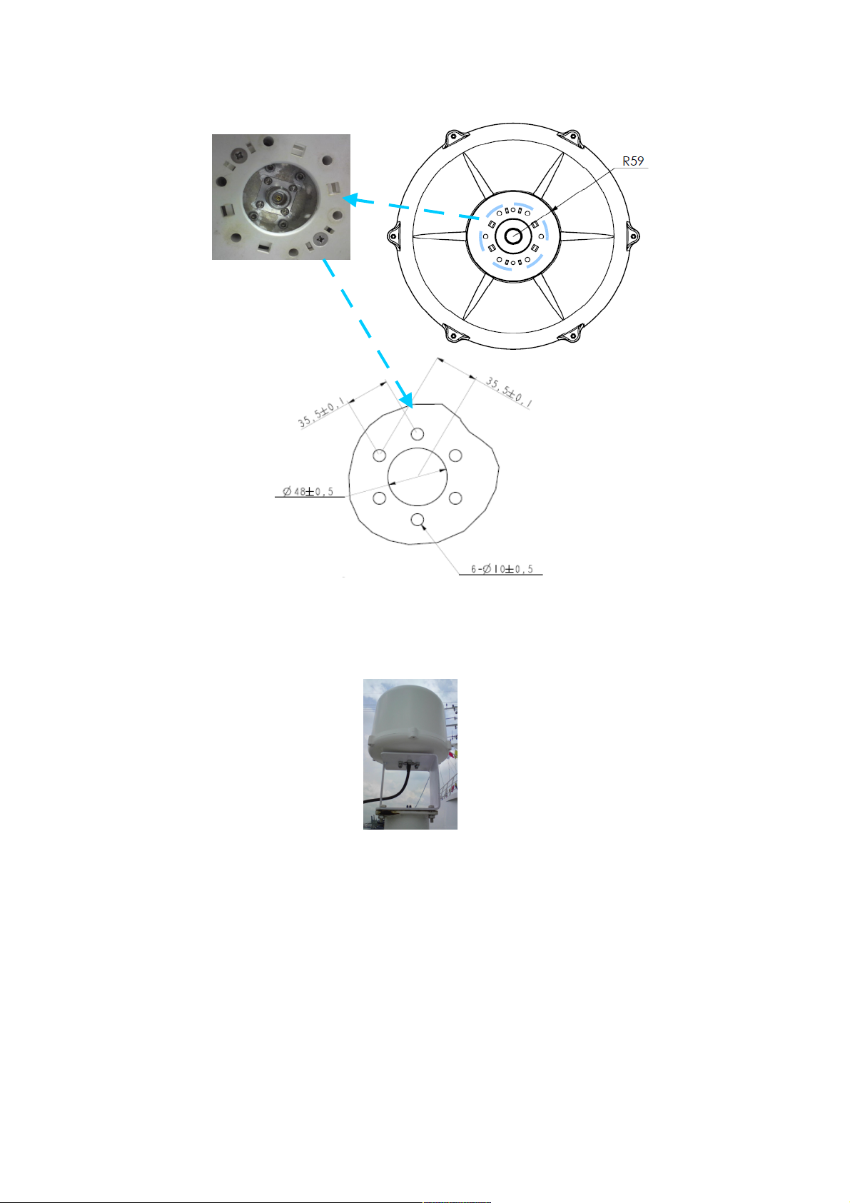
Note: In case of the existing mast’s flange in a vessel or ship does not fit the ADU’s
mounting base’s holes, a custom-made mechanical adaptation flange is to be
designed and plate, which acts as an interface between the existing mast and the
ADU.
ADU Mounting Base
Cut-hole Dimension
for flange
Page 16
ERS Installation Manual.
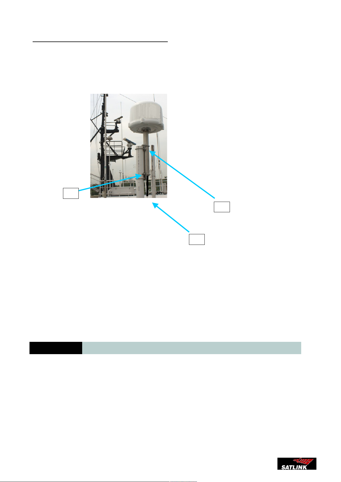
Mounting of ADU on Long Pole
The physical dimension of a long pole shall be preferably at 2 meter height with its
diameter ranges from Ø35 to Ø 50mm. In addition, the standard pole mount kit must be
used for the installation of the ADU onto the long post.
(1)Long Post
(2)Pole Mount
(3)Coaxial Antenna Cable
The standard pole mount kit includes the detailed installation guide.
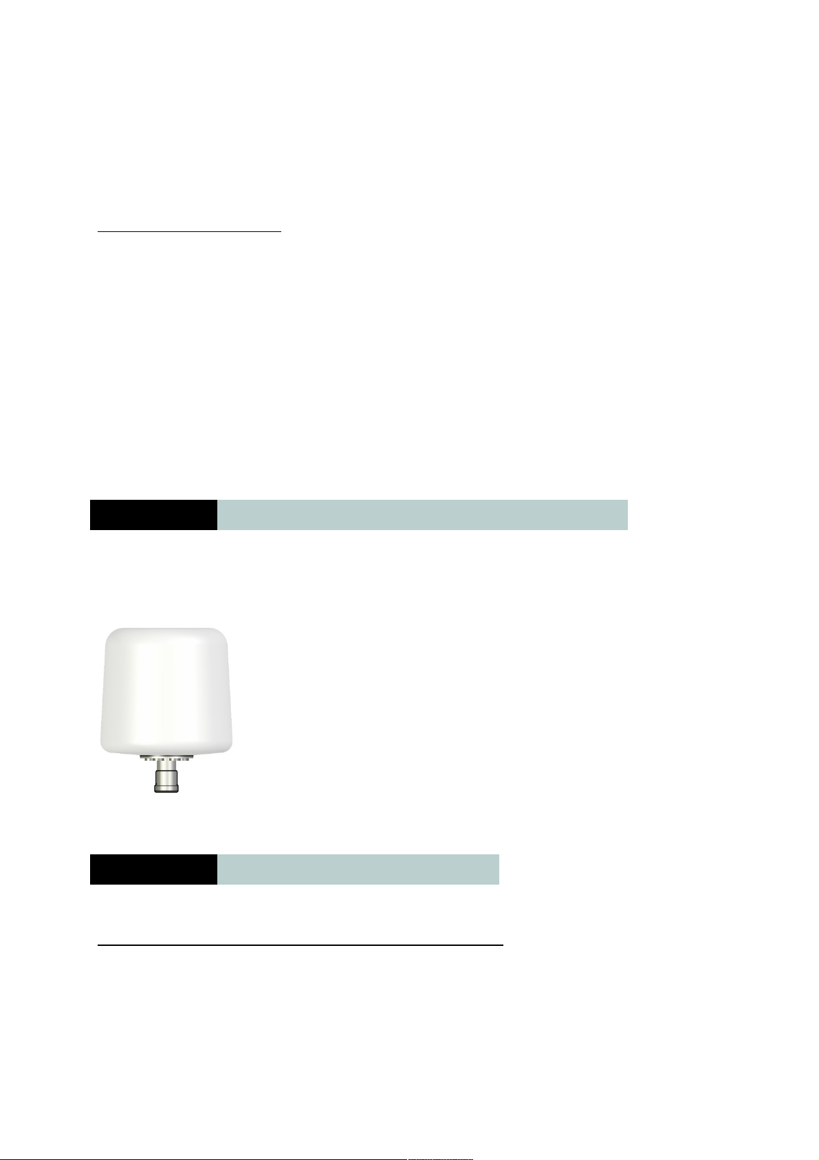
3.5 Antenna Dimensions
16
Page 17
FB250 Installation Manual.
4 Installation Guide BDU
The BDU is the controlling unit for the FB250 FleetBroadband system. It contains all user
interfaces, LED indicators and stores configuration data.
The built-in Web Console is used for easy configuration and daily use. The Web Console is
accessed from a computer connected to the terminal, using an Internet browser. No installation of
software is needed.
17
Page 18
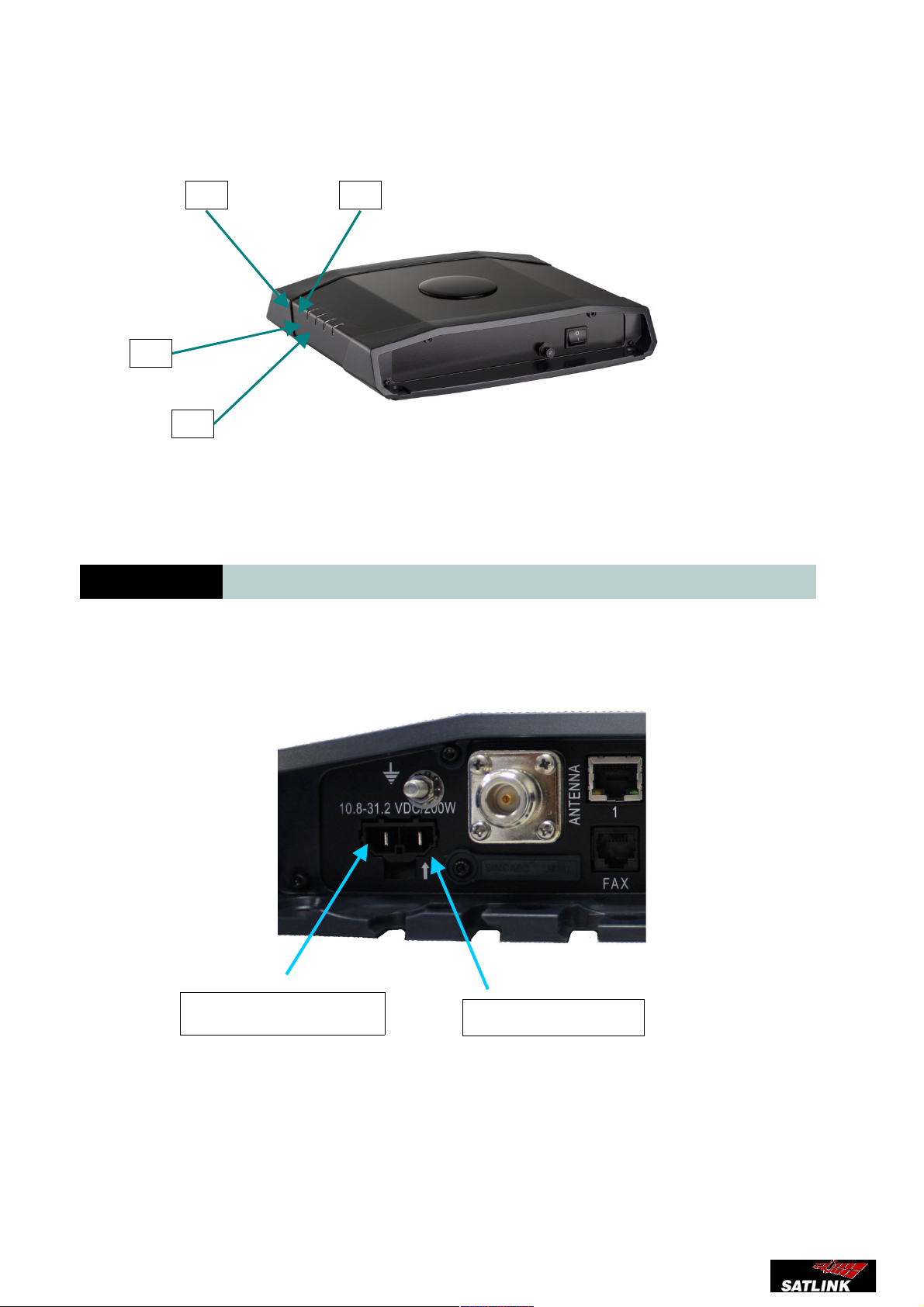
FB250 Installation Manual.
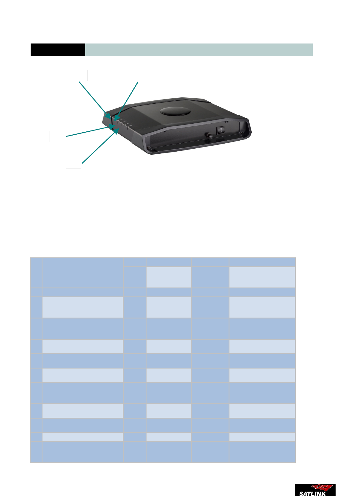
LED Indicators
(1) Power
(2) Antenna
(3) BGAN network
(4) Call/Message
4.1 Powering the BDU
Satlink FB250 BDU unit can use a power input since 10 to 32 Vcc and more specifications are
mentioned above.
You should have in mind this picture to power the unit where the polarity is
The voltage range is 10.5 - 32 VDC; 14A - 5.5A. It is recommended that the voltage is provided by
the 24 VDC power bus on the ship. Be aware of high start-up peak current: 20A @ 24V, 5ms.
18
Negative pole (-)
Positive pole (+)
Page 19
FB250 Installation Manual.
If a 24 VDC power bus is not available, an external 115/230 VAC to 24 VDC power supply can be
used.
4.2 Powering the BDU
4.3 Placing the BDU
When placing the BDU having it's important to consider:
- Ventilated aerea
- Dry environment
- Away from heating and electromagnetic sources
- Easy access place
- Ambient temperature between -20ºC ~ 35ºC
4.4 Connecting RF (Co-Axial) Cable
Follow these steps to connect the RF cable:
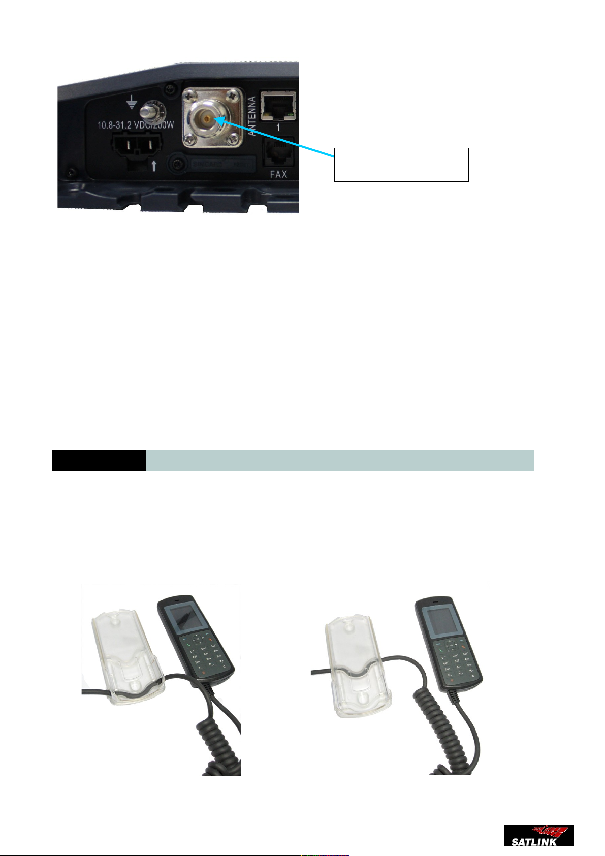
Connect the RF (Co-Axial) cable to the Antenna connector on the UE.
1. Tighten the cable connector to secure the RF cable to the UE.
19
Page 20
FB250 Installation Manual.
Note:
It's important that the RF cable is connected properly to the FB250 UE. Check that the RF
connector is securely tightened.
Connecting the BDU to the Power Supply
1. Connect the power supply adapter to the BDU power connector.
2. Connect the power supply to the AC outlet on the vessel.
4.5 Installing the handset
Satlink FB250 comes with a cradle to place the handset while is not in use, the cradle can
be secured either on a wall or placed on a desk.
To secure the handset to the cradle run the cable from the rail as shown in following
pictures
20
Antenna Cable
Page 21
FB250 Installation Manual.
4.6 BDU Connections
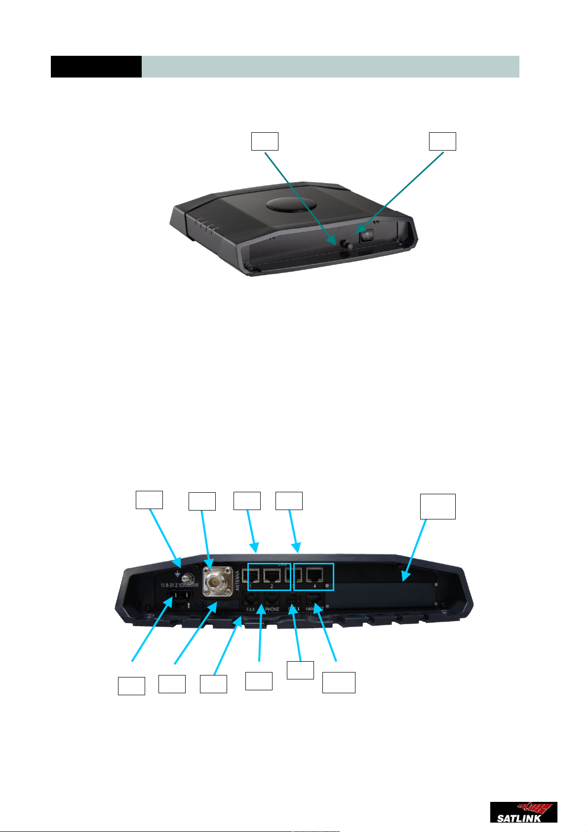
Front Panel
(1) Power button
(2) Circuit breaker
Rear Connector Panel
1) DC Power Connector
2) Earth Grounding Stud
3) Antenna Cable (Co-Axial) Connector
21
10
11
Page 22
FB250 Installation Manual.
4) 2 x LAN Port (RJ45 with PoE)
5) 2 x LAN Port (RJ45)
6) SIM Card Slot
7) Fax Port (RJ11)
8) Phone Port (RJ11)
9) GPS I/O Port
10) Primary Handset Port
11) Expansion Slot
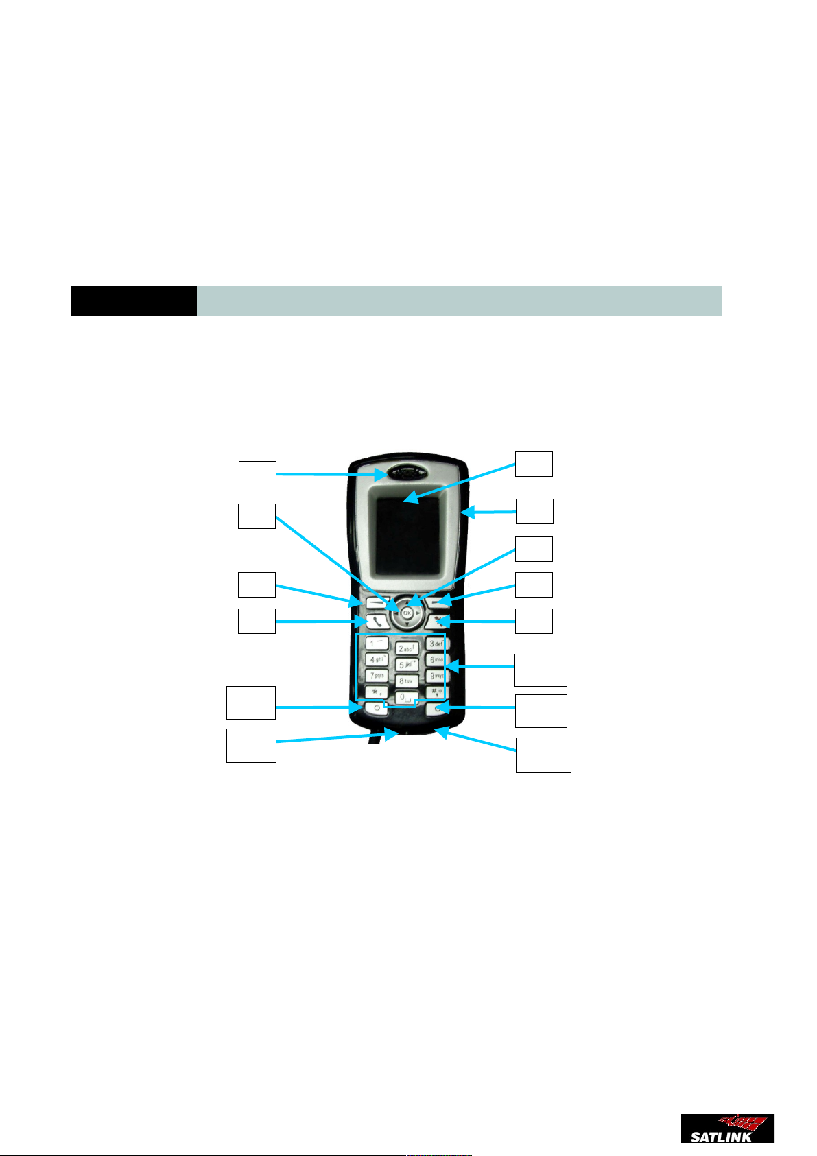
5 Primary Handset
This is the Primary Handset simple design colour screen unit
.
The Handset has been design for Satlink FB250 Unit.
Size is : 14 x 6 x 3 cm
Weight is: 80 gr.
(1) Earpiece
(2) Display
(3) Ear-set jack
(4) OK key
(5) 4-way navigation ring
(6) Select key (Left)
(7) Select key (Right)
(8) Call/Send key
(9) End key
(10) Keypad (Alpha-numeric)
(11) Power key
(12) Clear key
(13) Microphone
22
11
13
10
12
14
Page 23
FB250 Installation Manual.
(14) Service Port
(15) Speaker
*The speaker is located at the back of the Primary Handset.
6 Starting up the FB250
6.1 Using SIMCard
The FB250 UE requires a dedicated FleetBroadband SIM card to access the FleetBroadband
network and configure the settings of the UE. Please refer to your Airtime Service Provider for
more information.
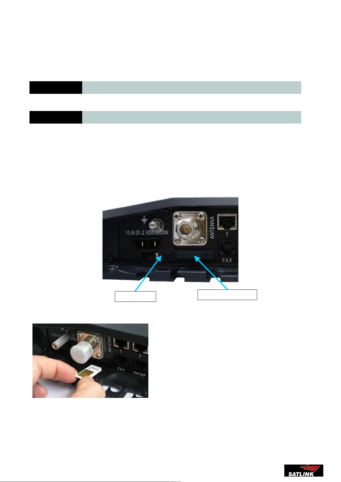
Follow these steps to install the SIM card:
1. Ensure the FB250 UE is powered down.
2. Remove the screw securing the SIM card protection cover.
3. Remove the SIM card protection cover.
4. Insert the SIM card into the cardholder.
5. Install the SIM card protection cover.
23
SIM Card Cover
Screw
Page 24
FB250 Installation Manual.
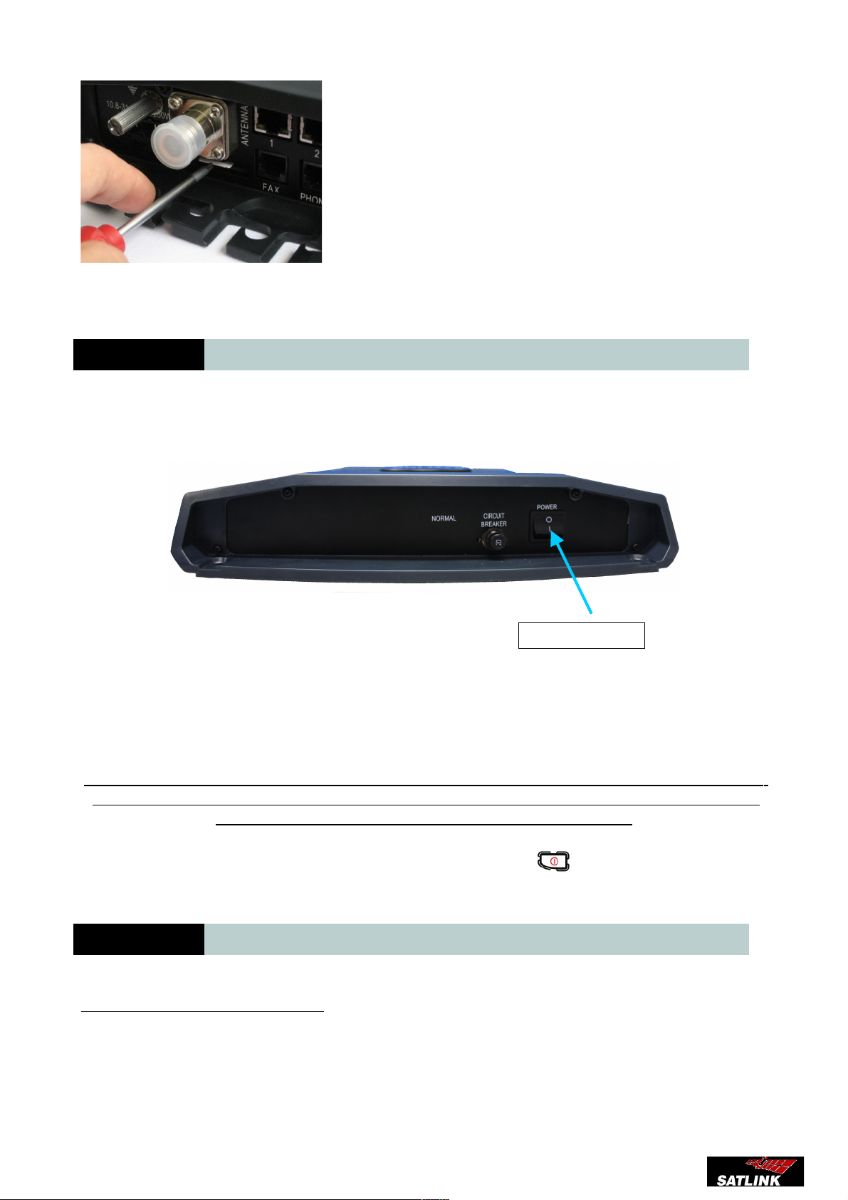
6. Install the screw to secure the SIM card protection cover.
6.2 Switching On the Equipment
To switch on the UE, use the Power Switch on the UE front panel.
When the UE is switched on, the Power LED indicator on the terminal lights up green.
For the first time usage, the UE will take about two minutes to acquire the new GPS and then
register to the network. Once the registration to the FleetBroadband network is completed,
you can proceed to use the UE for all supported services.
To switch off the UE, tip the Power Switch back or use the Power key located on the Primary
Handset.
6.3 PIN Number
Entering the SIM PIN for the UE
When you acquire the SIM card from the Airtime Service Provider, a PIN (Personal Identification
Number : 4 to 8 digits) is provided together with it. You can change the PIN
24
Power Switch
Page 25
FB250 Installation Manual.
The PIN (Personal Identification Number : 4 to 8 digits) is supplied together with the SIM card
when you acquire it from the Airtime Service Provider. You can change it For more information on
the Primary Handset, refer to PIN Management.
Depending on your SIM card, you may have to enter a SIM PIN to use the system. You can enter
the PIN using the Primary Handset or using the Web Console.
Note: You will need to enter the PIN at start-up if the UE has been powered down.
Entering the PIN using the Primary Handset
Follow these steps to enter the PIN:
1. Using the keypad on the Primary Handset, enter the PIN.
2. Press to confirm the PIN.
Note: If more than three (3) incorrect attempts were used to enter the PIN code, the handset
will be locked and will display “Unblock PIN or PUK Code”. You will be required to use the
PUK code to unlock the SIM card and to reset your PIN code.
6.4 Using the Web Console
Entering the PIN using the Web Console
Follow these steps to enter the PIN:
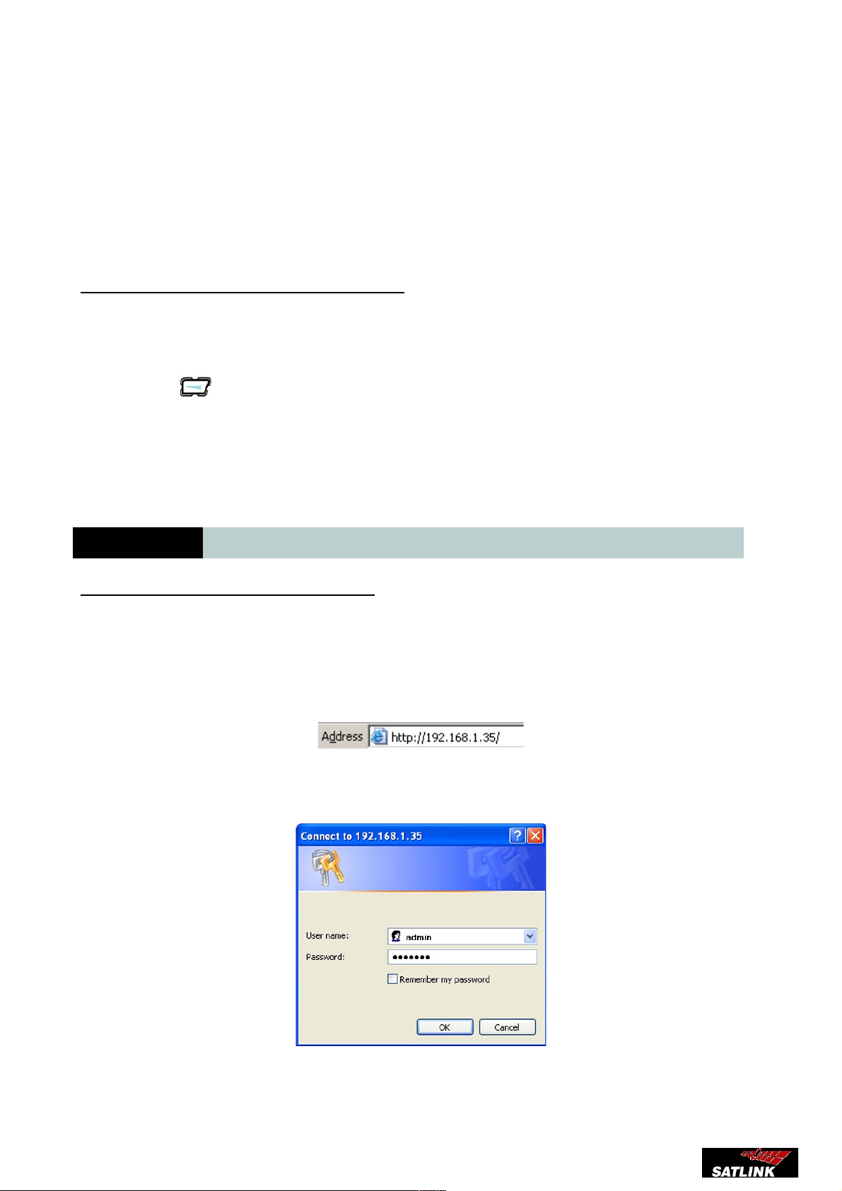
1. On a computer connected to the terminal, open your browser and type http://192.168.1.35
in the Address field and press Enter.
The Login screen appears.
2. Type in admin in the Username field and satlink in the password field. Click OK.
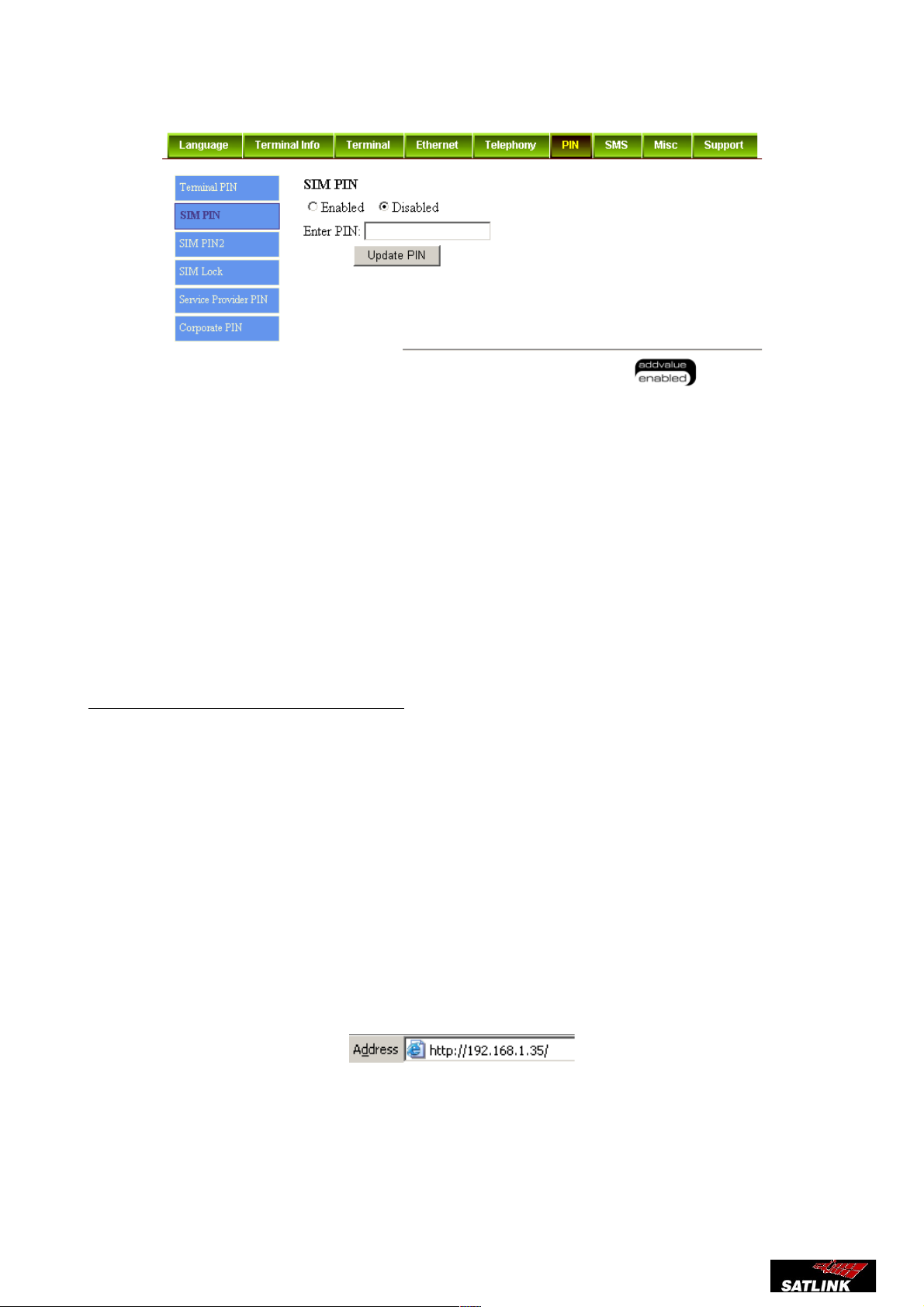
3. Click Settings on the Web Console.
25
Page 26
FB250 Installation Manual.
4. Click PIN.
5. Select Enabled to set the SIM PIN.
6. Enter the PIN number in the space provided and click Update PIN.
Note: You have 3 attempts to correctly enter the PIN, before you are asked to enter the PUK
(Pin Unblocking Key). The PUK is supplied with your SIM card.
Enter the PUK followed by a new PIN of your own choice. The PIN must be from 4 to 8 digits
long.
If you enter a wrong PUK 10 times, the SIM card will no longer be functional, and you have
to contact your Airtime Service Provider for a new SIM card.
Making the first data connection (LAN)
Before connecting to the LAN interface
For the LAN (Local Area Network) interface to work without any further setup, the computer must
be set up to obtain an IP address and a DNS server address automatically.
Connecting a computer to the LAN interface
Follow these steps to connect a computer to the UE:
1. Power up your computer
2. Connect your LAN cable between the network connector on your computer and the first
LAN connector on the UE.
3. To check the connection, open your browser and type http://192.168.1.35 in the Address
field and press Enter.
The Login screen appears.
4. Type in satlink in the Username field and satlink in the password field. Click OK.
26
Page 27

FB250 Installation Manual.
27
Page 28
FB250 Installation Manual.
6.5 LED Indication
(1) Power
(2) ADU / GPS
(3) BGAN network
(4) Call/Message
The LED gives information about the status of the BDU during the diferent stages of
the initialization
Action LED
LED 2 LED 3 LED 4
Termi
nal/Po
wer
ADU/GPS BGAN
Network
Call&Message
1 BDU is off OFF OFF OFF OFF
2 The BDU is power ON Steady
Ambe
r
- - -
3 System is booting up Blinki
ng
Green
- - -
4 System successfully boot up Steady
Green
- -
4 BDU detects failure. Steady
Red
- - --
5 ADU is powering up. - Blinking (fast)
Amber
Blinking
(fast) Amber
-
6 ADU is calibrating.
-
Blinking (slow)
Amber
Blinking
(slow)
Amber
-
7 ADU is OK but no GPS
position (Acquiring GPS)
- Blinking (fast)
Green
Blinking
(fast) Green
-
ADU is OK and new GPS fix
acquired
- Steady Green Steady
Green
-
8 ADU is not OK - Steady RED Steady RED --
9 System performs satellite
search but still no GPS fix
(Acquiring GPS)
-
Blinking (fast)
Green
Blinking
(fast) Amber
-
28
Page 29

FB250 Installation Manual.
10Attempting network
registration using stored GPS
(GPS is still acquiring in
parallel)
- Blinking (fast)
Green
Blinking
(slow)
Amber
-
11Attempting network
registration using live GPS
- Steady Green Steady
Amber
-
12Network failure - - Steady RED --
13Ready for voice - - Blinking
(slow)
Green
-
14Ready for packet data - - Blinking
(fast) Green
-
15Ready for all - - Steady
Green
-
16Full service but GPS lost
(connections not dropped)
- Blinking (fast)
Green
Steady
Green
-
17Primary handset Present - - - Steady Green
18Pending message(s) /SMS(s)
available
- - - Blinking (slow) Amber
19Incoming call - - - Blinking (slow) Green
20Outgoing call - - - Steady Amber
21Switching OFF equipment
either on handset or on power
switch
Blinki
ng
(slow)
Green
- - -
Registering with the FleetBroadband Network
When the UE accepts the SIM PIN, the FB250 system starts the registration procedure with the
FleetBroadband network.
You can monitor the registration procedure by looking at the Antenna and Terminal indicators on
the LED panel of the UE. Note that this procedure may take a few minutes.
Making the first voice call
When the Antenna and Terminal LED indicators on the terminal both light steady green, you are
ready to make or receive the first voice call.
Making a voice call from the terminal
To make a call from the Primary Handset connected to the terminal, dial
00 <country code> <phone number> followed the key.
To make a call from an analog phone (optional) connected to the terminal’s RJ11 port, off-hook the
phone and dial
00 <country code> <phone number>
29
Page 30

FB250 Installation Manual.
Making a voice call to the UE
To make a voice call to a phone connected to the UE, dial + <Mobile number>.
• + is the prefix used in front of the country code for international calls.
• Mobile number: The mobile number of the UE you are calling. The
first part of the number is always 870, which is the “country code” for the
BGAN system.
Note: There are two Voice numbers, one for Fax and one for Standard Voice.
The numbers are provided by the Airtime Service Provider.
7 Servicing the BDU
7.1 Factory Reset
The factory reset bring backs the unit to the original configuration. This action can be done
either through the primary handset or through the webconsole.
Warning:
All the settings and user data (e.g., Phone Book, GPS, etc.) of the FB250 UE will be cleared
and reset to the default settings. If you do not wish to lose critical user data such as Phone
Book, please use limited reset option available via Primary Handset
Factory reset using the primary handset
• Access the Terminal Menu
• Select the Factory reset option
• Type '0000' as password
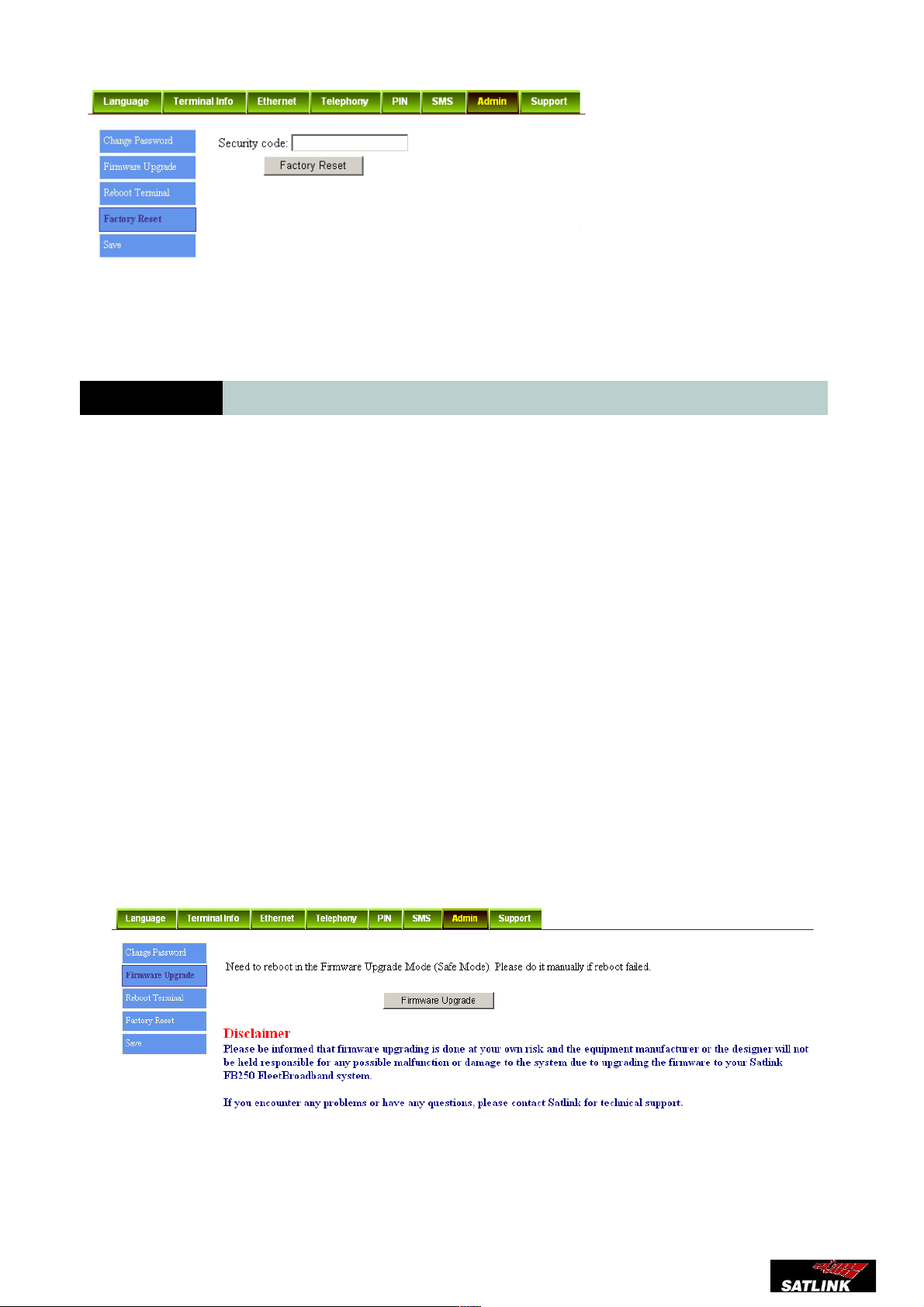
Factory reset using the webconsole
• Click on Settings icon.
• Navigate to Admin tab
• Click on Factory reset
30
Page 31
FB250 Installation Manual.
Enter the Security code 0000 and click Factory Reset.
7.2 Firmware upgrade
Firmware upgrade is to update your FB250 UE with the latest firmware. Please refer to your respective
distributor for your firmware download.
Warning:
DO NOT abort the upgrading process or unplug the power of the FB250 UE during the firmware
upgrade process at any time. Doing so will corrupt the existing firmware loaded onto the FB250 UE.
Note:
Before upgrading with the new firmware, please read through the release notes that is provided with
the new firmware.
Follow these steps to upgrade the firmware for your FB250 UE:
1) Download or acquire the new firmware from your respective distributor and save it in your
computer’s hard drive.
Note:
Make sure the FB250 UE is switched on and connected to the desktop/laptop computer using the LAN
cable.
Select Firmware Upgrade.
Read the Disclaimer message carefully before proceeding with the Firmware Upgrade.
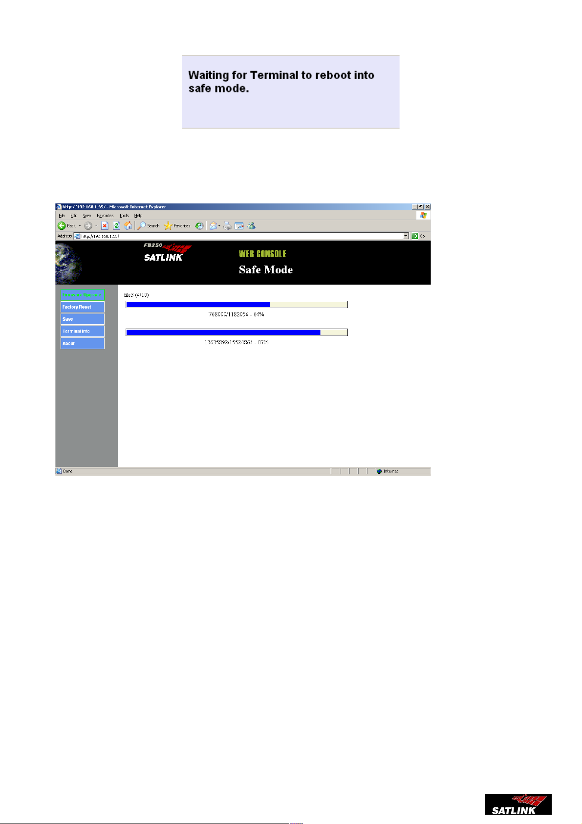
2) Cick Firmware Upgrade.
The FB250 UE will reboot into Safe mode.
31
Page 32
FB250 Installation Manual.
3) Select the downloaded new firmware and click Start.
Firmware upgrade will take approximately 10 to 12 minutes to complete.
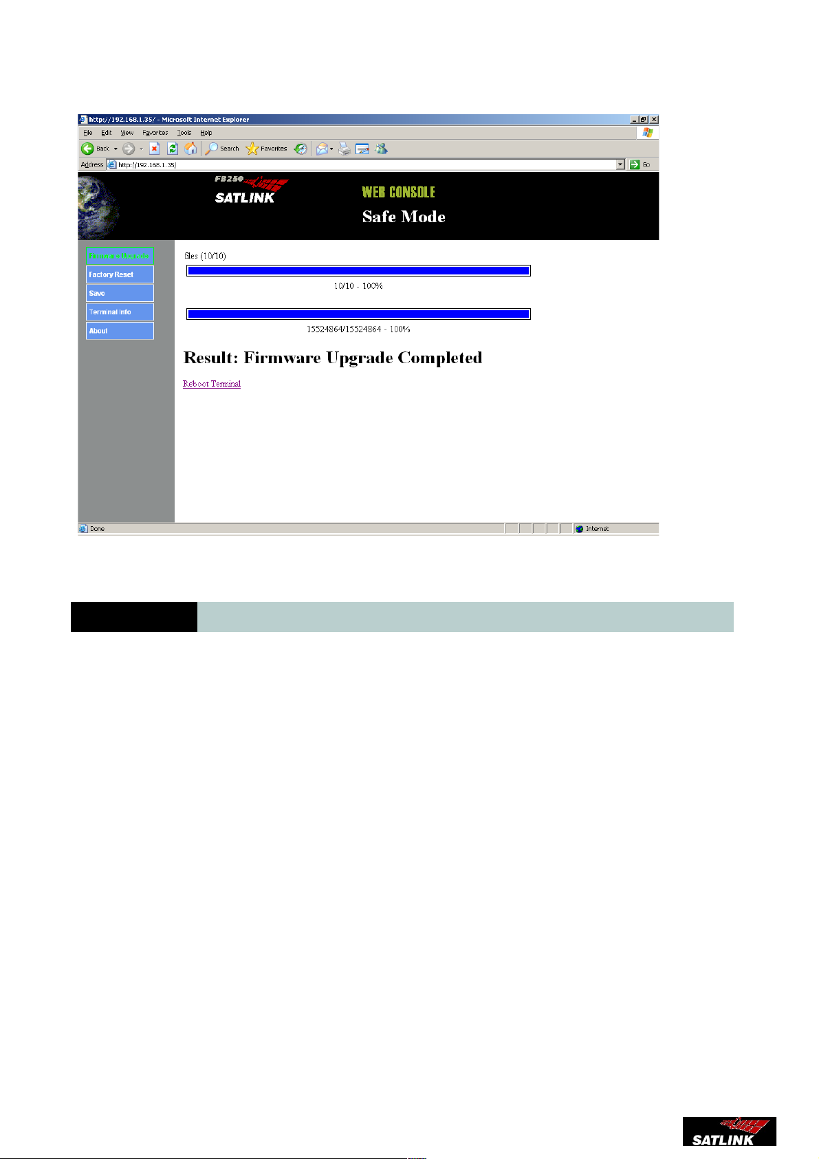
You will be prompted with the Result: Firmware Upgrade Completed message.
32
Page 33
FB250 Installation Manual.
4) Click Reboot Terminal to reboot the FB250 UE.
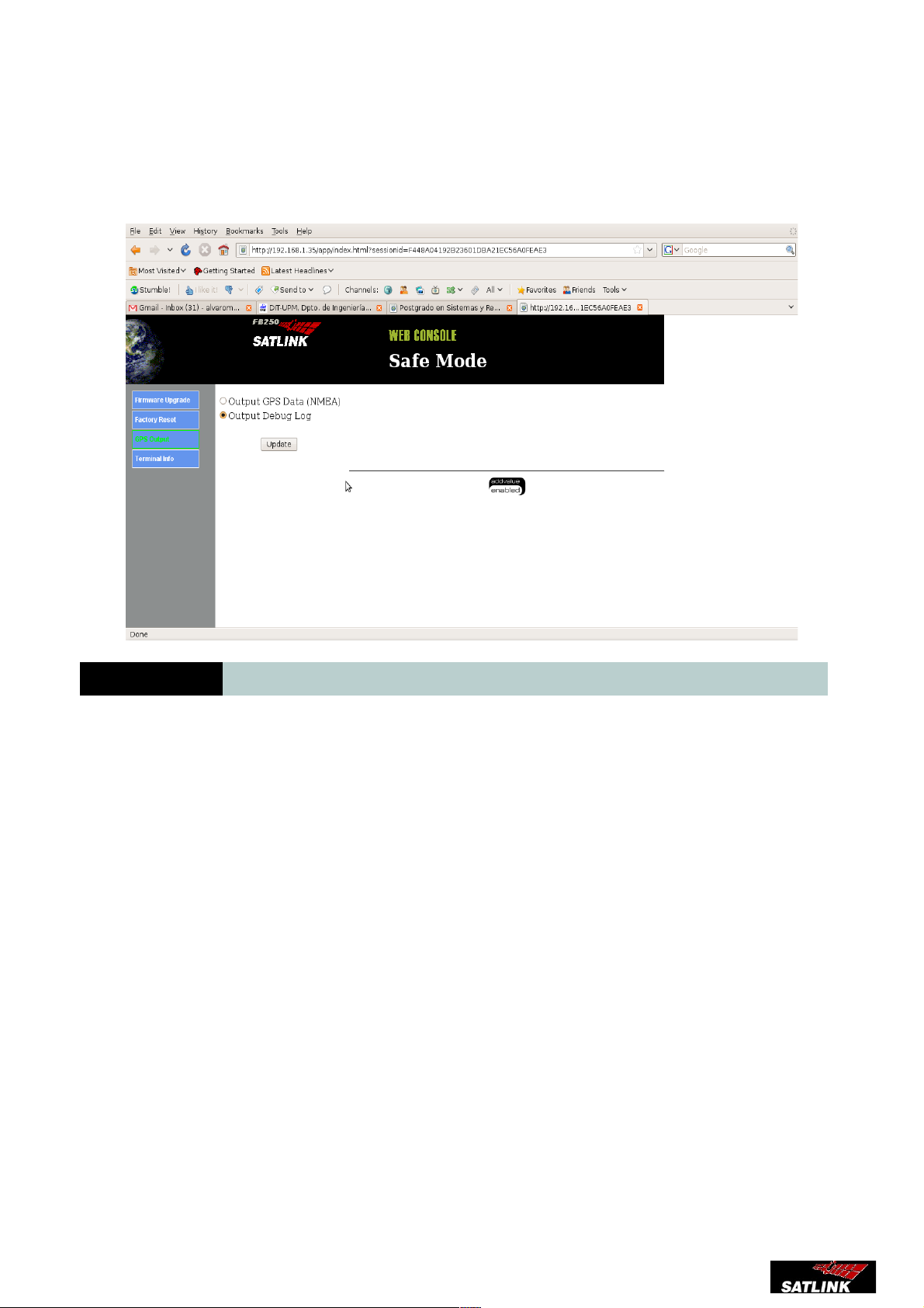
7.3 Safe mode
Safemode provides a protected environment to apply changes to the FB-250. The
following actions are available from the safe mode menu
• Firmware upgrade
• Factory reset
• GPS output
• About
Accesing safe mode is done through these steps
• Power off the unit if it's on using the main switch
• Remove de SIM cover
• Using a screw driver push and hold the safe mode button located beside the SIM card
slot
• Power on the unit using the main switch
• Wait until the 4 leds blink amber
33
Page 34
FB250 Installation Manual.
GPS output
This option allows to configure the NMEA port either as GPS output or as debug channel
for servicing purposes
8 Troubleshooting and basic errors
The ADU is steady red
Tight the antenna cable to the BDU
Network LED is steady amber
Check with yout provider that the SIM card is active.
I can't open streaming services
Check with your provider if your SIM cards allow streaming services
My fax doesn't work
Check that your fax complies with Group 3 specifications
My fax is Group 3 and it's not working
Fax services is only active above 20 degrees elevation. Check your current altitude
servicing under Satellite menu in the Webconsole. If your altitude is above 20 degrees
check that telephony ports are correctly configurated.
34
Page 35

FB250 Installation Manual.
How many primary PDP can I have at the same time
Satlink FB250 is designed to have one primary PDP but multiple secondaries PDP
How many secondary PDP can I have at the same time
The maximum streaming allowed in a FB-250 is 128 kbps, therefore you can have as
many secondary PDP while the sum of these secondary PDP is less or equal to 128 kbps
I have set up a 128 streaming but I can't do phone calls
BGAN network only supports a max of 64 kbps while doing a phone call
Why sometimes my streaming doesn't activate or I can't make 3.1 kHz calls
Services availability rely on the elevation angle between the FB250 and the selected
satellite. The following table shows which services are available on different elevation
bands
Why do I make some changes that are not persistant after I power off the BDU?
The BDU has a save cycle every 15 minutes, if you want to secure your changes. You
have to click on the Save option under the Admin tab in the Settings menu
35
Elevation bands <10 10-15 15-20 20-45 45-90
Max Single Streaming 180 / 102 180 / 142 209 / 160 240 / 182 240 / 200
AMBE Support YES YES YES YES YES
ISDN Support NO NO NO YES YES
Max Streaming + AMBE 176 / 51 176 / 71 205 / 80 236 / 91 236 / 100
Max Streaming + ISDN NO NO NO 116 / 71 116 / 71
Max Background (BG) 232 / 292 266 / 372 384 / 493 492 / 493 492 / 493
Page 36

FB250 Installation Manual.
TECHNICAL SPECS
Satlink FB250
Rounter
LAN/Ethernet: 4 x 10Base-T Ethernet Ports including 2 Power over Ethernet (PoE)
LAN/Standard: IEEE 802.3 10Base-T Ethernet
LAN/Network Protocols: TCP/IP, NAT, PAT, HTTP, DHCP Server, MAC address permission/rejection
LAN/Cabling & onnector: RJ45 / Cat. 5, UTP, 100 meters max
LAN/LED Indicator: Link/Act & Full Duplex/Collision
WAN/BGAN: Inmarsat C9 284 kbps (Uplink) / 284 kbps (Downlink)
WAN/BGAN: Inmarsat C9 284 kbps (Uplink) / 284 kbps (Downlink)
WAN/BGAN Connection type: Standard background
Streaming 128 kbps, 64 kbps or 32 kbps
WAN/BGAN Connections: 1 x Standard background
1 x 128 kbps streaming
2 x 64 kbps streaming
4 x 32 kbps streaming
1 x 64 kbps and 2 x 32 kbps simultaneously
BDU
Weight 2.6kg
Dimension: 314.7 x 295 x 59.4 mm
Temperature: Storage -40°C to +80°C.
Operational -25°C to +55°C
Humidity: 95% at temperature of +40°C (non-condensing)
Power: 12VDC +/-10% to 24VDC +/-30% (+10.8VDC - +31.2VDC).
Antenna connector: N-Type female
External phone interface: 1 x RJ11 for 2-wire handset (TBR-38 ETSI standard)
External fax interface: 1 x RJ11 for G3 Fax, Modem following ITU-T V-Series Recommendations or 64 kbps PCM
voice.
Expansion Slot (Internal): 1 x Analog (2-wire phone interface)
1 x LAN Interface and power supply of +6VDC, 0.5A.
Expansion Slot dimension: Approx. 93 x 76 x 17 mm
LED Indicator: Terminal / Power, Network Status, ADU/GPS, Call/Message
NMEA: RS232 port with NMEA183 output RMC and ZDA
Voice: Standard voice quality 4kbps AMBE+2
High quality voice 3.1 KHz Audio
BDU Power consumption: 23W (Total power consumption ADU+BUD+Handset but without consideration of
expansion slot & PoE = 65.5W)
Protection class: IP20
Receiver operational tuning range 1525.0 - 1559.0 MHz, in steps of 1.25 kHz
Transmitter operational tuning range 1626.5 - 1660.5 MHz, in steps of 1.25 kHz
Handset
Display: 2”, 220 x 176 pixel TFT, 262K Color LCD
Weight: Approx. 80grams
Dimension: 140 x 55 x 20 mm
Temperature: Storage -30°C to +70°C.
Operational -20°C to +55°C
Protection class: IP66
Features Configuration setting
Phone book access
Call log function
SMS Messaging
5-way menu navigation switch for user-friendly menu operation
Hands free operation via plug-in headset
Support multiple languages (English, Spanish)
Handset Power Consumption: 2.5W
System
Certification: Inmarsat TA
GMPCS
FCC regulatory
R&TTE / CE Marking
RoHS compliance
EIRP EIRP is specified at 15.1dBW by SDM Vol.5 Ch4 section 2.3.1
G/T G/T is specified at -15.5 dB/K in SDM, Vol. 5 ch4 section 2.4.1
Antenna
Weight: 3.8kg
Dimension: H277mm x D319.5mm x R59mm
Temperature: Storage -40°C to +80°C.
Operational -25°C to +55°C
Humidity: Up to 95% @ 40°C
Vibration / Random Vibration: Operational:
1.05 Grms in each of three mutually perpendicular axes with the following spectral density
36
Page 37

FB250 Installation Manual.
5-20 Hz………….0.02G²/Hz
20-150 Hz……….-3dB/octave
Vibration / Survival: Random vibration of 1.7g rms for a period of two hours in each of three mutually
perpendicular axes (six hours total). 1.70 Grms with the following spectral density:
5-20 Hz………….0.05G²/Hz
20-150 Hz……….-3dB/octave
Vibration / Sinusoidal Frequency Vibration (IEC
60945)
2Hz to 5Hz and up to 13,2 Hz with excursion of ±1mm ±10%
(7m/s² maximum acceleration at 13,2Hz)
Above 13,2 Hz and up to 100Hz with a constant maximum acceleration of 7m/s²
(For further details please consult standard IEC60945)
Vibration / Shock: 20g 11ms Half sine
2 shocks in each of three mutually perpendicular axes (Six in total).
Ship motion, minimum: Motion: Amplitude:
Roll + 30º @ 8 sec
Pitch + 10º @ 6s
Yaw + 8º @ 50 s
Turning Rate +/- 6 deg/s @ 1 deg/s2
Maximum induced acceleration for Above Deck Equipment:
Motion: Amplitude:
Roll 0.5 g tangential
Pitch 0.5 g tangential
Yaw 0.2 g tangential
Surge 0.2 g
Sway 0.2 g
Heave 0.5 g
Recommended Antenna Cable: Cable loss from 0 to 12 dB at 1.6 GHz
GPS Built-in antenna and 16 channel GPS engine
The Beam width of the antenna: +/- 20Deg on Azimuth Axis (Elevation is 0 deg) , +/- 30deg on Elevation axis (horizon,
Elevation is 90deg) , both based on -3dB Gain from G max for both TX and RX band
ADU Power consumption: 40W
Protection class: IP55 / Breathing design
++
37
 Loading...