

Page 1
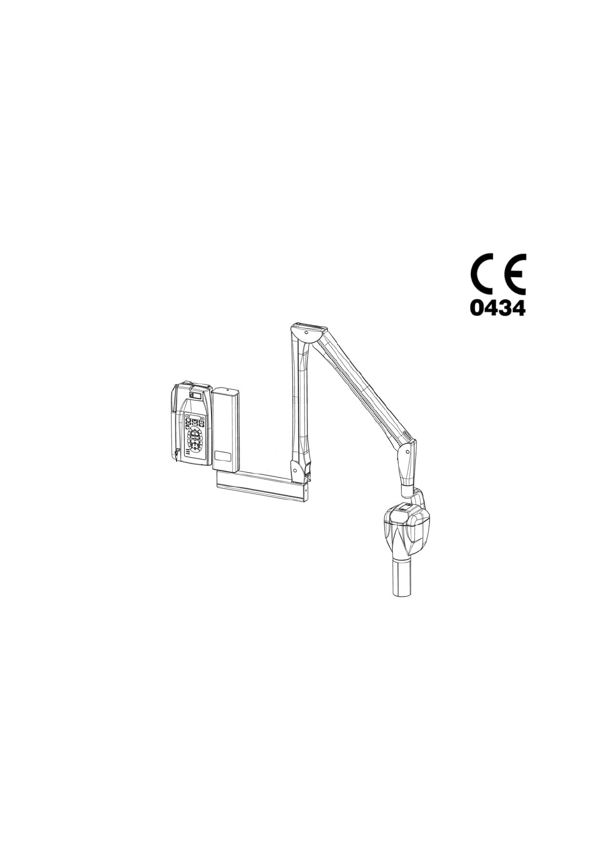
X-Mind
DC
Intraoral x-ray system at constant potential
USER’S MANUAL
This manual should always be kept in proximity to the device
Page 2

SUMMARY page 2
INTRODUCTION page 3
PRELIMINARY INFORMATION page 4
USER INFORMATION page 5
WARRANTY CONDITIONS page 6
TRANSPORT CONDITIONS page 7
SAFETY WARNINGS page 8
1.
“X-Mind
DC” X-RAY SYSTEM
page 9
2. SYSTEM COMPONENTS page 10
3. IDENTIFICATION TAGS page 12
4. CONTROL PANEL page 13
5. SYSTEM CONFIGURATION page 14
6. OPERATING INSTRUCTIONS page 15
7. CHART OF DEFAULT EXPOSURE VALUES FOR THE 12” CONE page 22
8. CHART OF DEFAULT EXPOSURE VALUES FOR THE 8” CONE page 23
9. PROGRAMMING DEFAULT EXPOSURE VALUES page 26
10. RESTORING ORIGINAL VALUES page 28
11. DIAGNOSTICS page 29
12. ERROR MESSAGES page 30
13. SYSTEM TECHNICAL DATA page 32
14. SUGGESTED MAINTENANCE page 36
15. CLEANING THE OUTER SURFACE page 37
16. IF A REPAIR BECOMES NECESSARY page 37
17. DISPOSAL page 37
18. ACCESSORIES page 38
TABLE OF CONTENTS
Page 3

The radiographic system described in this manual is a “wall installation”.
SATELEC
®
S.A.S. reserves the right to modify its products and manual without notice.
SATELEC
®
S.A.S. shall not be liable for any incorrect use of the information contained in this
manual.
Any copies, even partial, of this manual are permitted solely for in-house use.
INTRODUCTION
Page 4
Before beginning to use the “X-Mind
DC” X-ray system, it is advisable to carefully read and follow
the instructions contained herein should be carefully read and followed, in order to obtain the
best possible performance.
Always pay close attention to the CAUTION, WARNING and PLEASE NOTE messages when
operating the system.
LEGEND
CAUTION
The word CAUTION identifies those situations which might compromise the operator’s
personal safety or cause personal injuries.
WARNING
The word WARNING identifies those situations which might compromise the X-ray system’s
performance.
PLEASE NOTE
The words PLEASE NOTE are used to give special indications to facilitate maintenance or make
important information clearer.
PRELIMINARY INFORMATION
Page 5

Dear Customer,
Thank you for having chosen the “X-Mind
DC” X-ray system.
It was designed and manufactured by “de Götzen
S.r.l.” in collaboration with “Satelec
®
S.A.S.”
and is the result of many years of experience in the fields of radiology and advanced electronics
applications.
This high performance system represents ongoing development of technological research serving
dental radiography.
It is delivered with all the necessary technical documentation, which must always be kept close at
hand for reference.
PLEASE NOTE
This manual does not contain all the recommendations and the obligations with respect to the
possession of a source of ionizing radiation – as they vary from country to country – but only the
most common ones.
The user must consult his country’s legislation in order to comply with all local ordinances.
USER INFORMATION
Page 6

Inappropriate use or any arbitrary tampering with the equipment shall release “de Götzen
®
S.r.l.” or “Satelec
®
S.A.S.”, the manufacturer of the “X-Mind
DC” system, from any warranty
service or liability.
The warranty is valid only if the following precautions are taken:
9 any repairs, modifications, adjustments, re-calibrations must be performed only by “de
Götzen
®
S.r.l.” for “Satelec
®
S.A.S.”
9
installation must be done by professionally qualified technicians. pursuant to existing
regulations
9 the system must be installed and used in compliance with the instructions set forth in this
Manual and for the purposes and applications for which it was designed
9 the power supply must be adequate to supply the required power indicated in the X-ray
system’s nameplate data
9
in order to safeguard the warranty rights, please fill in the enclosed Warranty
Document, immediately completion of the installation , with the help of the technician
WARRANTY CONDITIONS
Page 7

The “X-Mind
DC” X-ray system shall be shipped at the receiver’s sole risk.
All claims for damages or shipping loss with respect to the shipment must be noted in the
presence of the shipping agent.
In case of shipping losses, or actual or suspected damage, the receiver shall note the appropriate
reserves on the way-bill or the consignment note.
TRANSPORT CONDITIONS
Page 8
A few safety recommendations are listed below which should be followed when using the “X-Mind
DC” radiographic system.
PROTECTION AGAINST RADIATION
“The general principles regarding safety and protection of workers and people” must always be
applied when using the unit:
1. Justification of the practice
2. Protection Optimization (ALARA)
3. Reduction of individual dose limits and risks
The X-ray system may only be used by authorized and qualified personnel.
All personnel present during the radiological examination must comply with safety measures
established with respect to radiation protection.
For his or her own safety, the operator must always remain at least 2 meters from the tube
head.
To protect the patient from unnecessary exposure to radiations, additional anti-radiation
protection may be used whenever necessary (i.e. aprons, collars, etc…)
This symbol calls ATTENTION to the danger of X-rays
ELECTRICAL SAFETY
The X-ray system contains high voltage.
When inspecting internal parts, always turn off the power before handling any electrical part.
The unit must be used only in environments which comply with all electric safety standards for
medical environments.
The unit is NOT equipped with protection against penetration by liquids; it is therefore necessary
to ensure that no water or other liquids penetrate the device, in order to avoid short circuits or
corrosion.
Always disconnect the X-ray system from the power supply before cleaning and disinfecting
operations.
MECHANICAL RISK
Before removing the tube head from the positioning arm, RELEASE THE SPRING, as the joint
might burst open and hit the operator.
PROTECTION AGAINST EXPLOSIONS
The X-ray system MUST NOT be used in the presence of disinfectants, flammable or potentially
explosive gases or vapors which might catch fire and cause damage.
In the event that disinfectants must be used, allow the vapor to disperse completely before
turning on the X-ray system.
SAFETY WARNINGS
Page 9

The “X-Mind
DC” X-ray system guarantees maximum safety for both the operator and the
patient.
It has been manufactured in compliance with the following European Directives:
directive 93/42/EEC on MEDICAL DEVICES and its amendments
directive 73/23/EEC on LOW VOLTAGE and its integration
directive 89/336/EEC on ELECTROMAGNETIC COMPATIBILITY
directive EURATOM 96/29 on ionizing radiation
and the following American Standard:
American Radiation Performance Standard 21 CFR, Subchapter J
The following protective measures were adopted in the design and construction of the unit:
9 Protection against the risk of electrical injuries, ensured by a grounded cable
9 Protection against radiation leakage , rendered negligible by the shielded casing
9 Protection against excessive radiation, thanks to immediate activation of the safety device
9 Protection against continuous service, since the system is designed, according to standards,
so as not to allow radiological overuse
9
Protection against exposure errors, by means of network compensation software, ensuring
constant blackening
9 Patient protection against dangerous radiations, through the improvement of the quality of
the radiation through the addition of an aluminum filter, in compliance with standards
9 Operator protection against irradiation ensured by the extendable hand control cable ,l
which provides a buffer zone of over 2 meters
9
Protection against the involuntary selection of “film” or “digit”, obtained, in compliance
with standards, by means of the confirmation of the selected touch key
“ELECTRO-MEDICAL” CLASSIFICATION
Pursuant to paragraph 5 of the general safety regulations EC EN 60 601-1/1998 on medical
equipment safety, the system is classified as: Class I - Type B
“MEDICAL DEVICES” CLASSIFICATION
Pursuant to the classification rules set forth in attachment IX of the EEC Directive 93/42 on
medical devices, the system is classified as: Class IIb
“E.M.C.” CLASSIFICATION
Pursuant to paragraph 4 of the EEC EN 55011, the system is classified as: Group 1 – Class B
1. “X-Mind
DC” X-RAY SYSTEM
Page 10
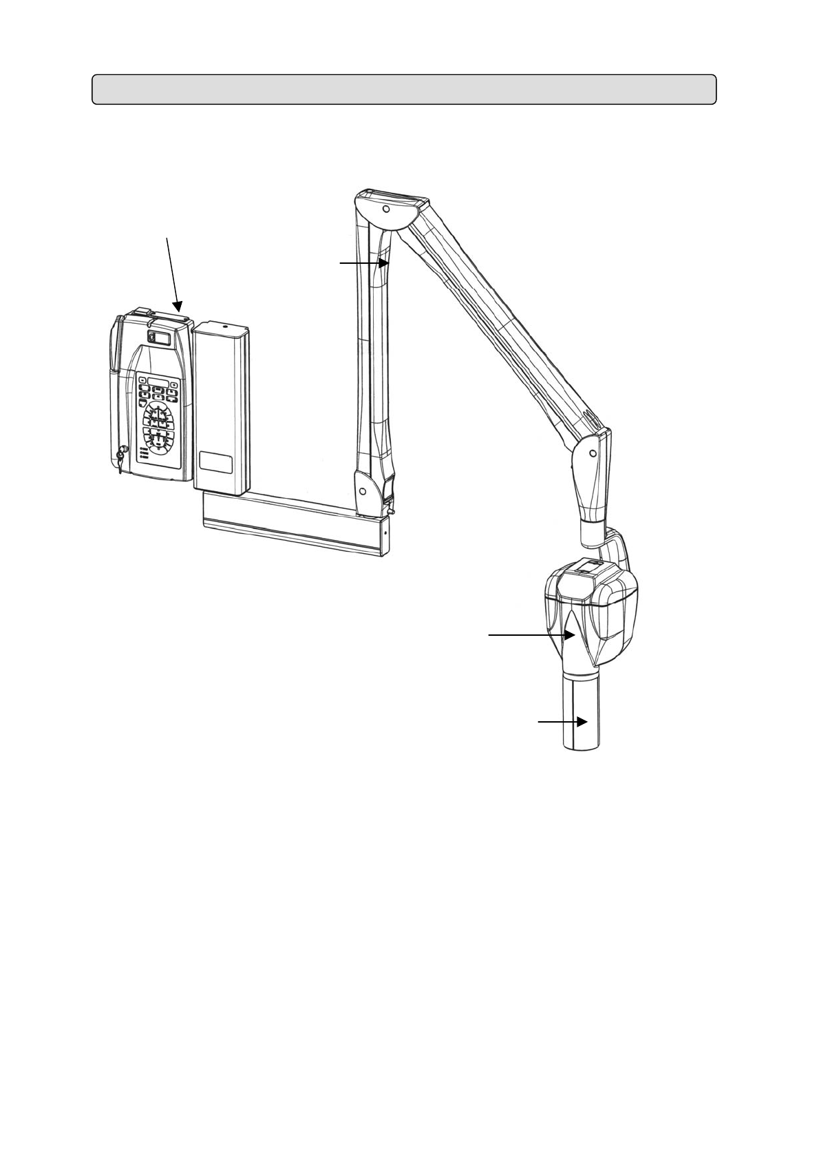
2. SYSTEM COMPONENTS
f
e
c
d
Fig.
1
Page 11

The “X-Mind
DC” x-ray system (Fig. 1) consists of:
c Tubehead
The tubehead is of the “monoblock” type with following characteristics:
high frequency generator at “constant potential”
double anode voltage 60kVp – 70kVp
double anode current 4mA – 8mA
The light alloy housing is divided into two compartments.
The high voltage transformer, the X-ray tube and the expansion chamber are submerged in
highly dielectric insulating oil inside a light alloy container.
The second compartment contains the electronic main board and the electronic control
board.
The X-ray tube is located in the back part of the housing thus allowing a focal spot to skin
distance (SSD) which is 50% higher than the traditional structure.
d Spacer Cone
Made of transparent polycarbonate, it allows for:
correct focal spot to skin distance
dimension, direction and centering of the X-ray beam
use of different x-ray techniques (bisecting and parallel techniques)
e Pantograph type arm
Thanks to the new shape and new mechanisms of the positioning arm, the height and depth can
be adjusted so as to precisely explore any spot in its reach.
It is made of light alloy with an “ABS” coating.
f Timer
The timer is the control panel used to manage the times and to safely use the tubehead.
It is “multi-technology” type and it is able to control both AC and DC x-ray systems.
The “CONTROL BUTTON” with safety button is used for the exposure.
The timer can be connected to n° 2 tubeheads:
n° 2 ALTERNATE CURRENT “AC” X-RAY UNITS: “X-Mind
AC”
or
n ° 2 DIRECT CURRENT “DC” X-RAY UNITS: “X-Mind
DC”
or
n ° 1 ALTERNATE CURRENT “AC” + n° 1 DIRECT CURRENT “DC” X-RAY UNITS:
“ X-Mind
AC
®
” + “X-Mind
DC”
PTIONAL
− short 8” (20 cm) cone – NOT AVAILABLE IN U.K.
− long cone 12” (31 cm) with a rectangular section - dimensions: 44x35 mm
− second “CONTROL BUTTON” with extension cable
− RX signaling lamp for external use: X-Mind
LIGHT
− remote control button: X-Mind
ECB
3. IDENTIFICATION TAGS
Page 12
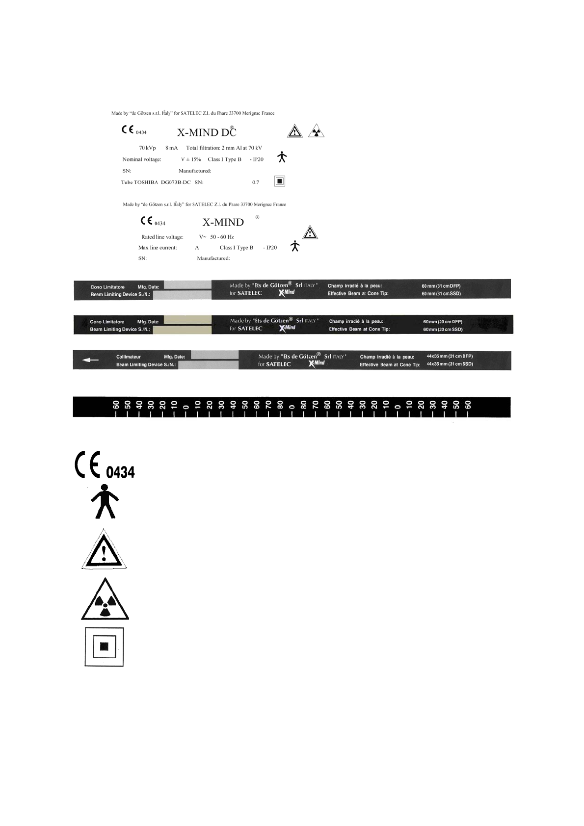
The identification tags on the tubehead, on the timer and on the cone indicate the model name,
the serial number, the manufacturing date and the symbols of the main technical characteristics.
ID TAG OF THE
“X-Mind
DC”
TUBEHEAD
ID TAG OF THE
“X-Mind
DC”
TIMER
ID TAG OF THE LONG 12” CONE
ID TAG OF THE SHORT 8” CONE
ID TAG OF THE RECTANGULAR CONE
GRADUATED SCALE TAG
Pictograms used
This symbol guarantees that the x-ray system complies with the regulations
contained in the European Directive EEC 93/42 regarding Medical Devices
The degree of protection against direct and indirect electric contacts is B type
Refer to Manual's instructions
Symbol indicating danger due to “ionizing radiations”
Size of the focal spot
Page 13
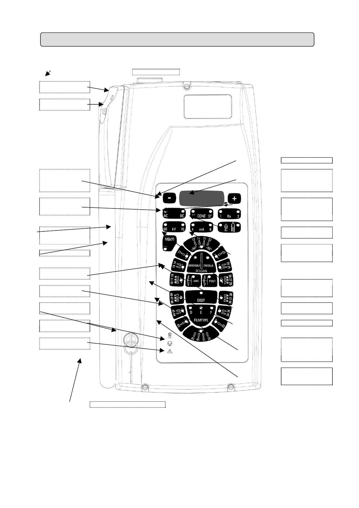
MAIN SWITCH
CONTROL
BUTTON
X-RAY
KEY
DISPLAY
KEY
TO DECREASE
EXPOSURE
TIME
KEY
TO INCREASE
EXPOSURE
TIME
TUBEHEAD
TYPE
INDICATOR
X-RAY DISTANCE
INDICATOR
TUBEHEAD
SELECTION
RADIOGRAPHIC
VOLTAGE INDICATOR
STORAGE
SELECTION OF TYPE
OF PATIENT’S
PHYSIQUE
UPPER
JAW TEETH
LOWER
JAW TEETH
X-RAY
CURRENT
INDICATOR
X-RAY
OUTPUT SIGNAL
OCCLUSAL EXAM
BITE-WING EXAM
PAUSE INDICATOR
MULTIFUNCTION
INDICATOR
DIGITAL
RADIOGRAPHIC
TECHNIQUE
CONVENTIONAL
X_RAY
TECHNIQUE
KEY SWITCH
4. CONTROL PANEL
Page 14
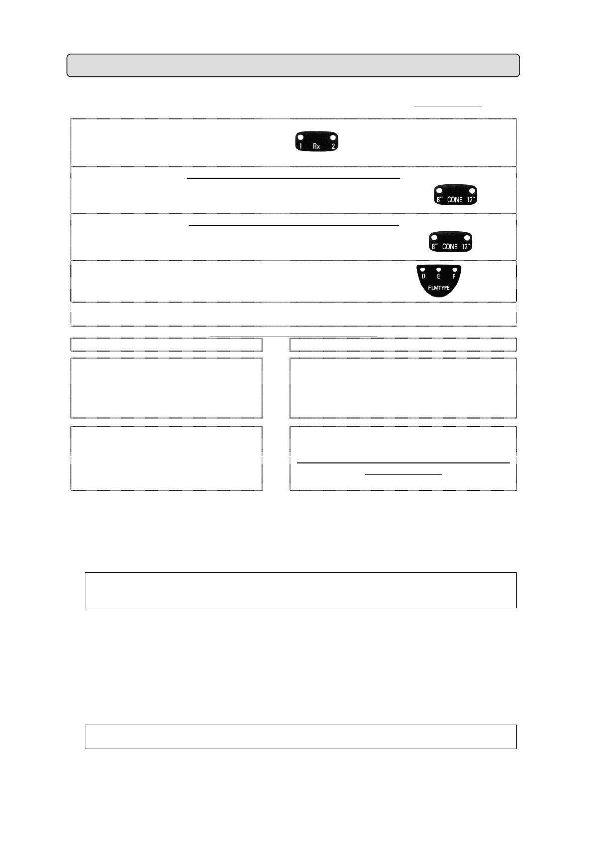
A. The “X-Mind
DC” x-ray system is factory configured for an operative “standard mode” which
determines:
N° 2 “X-Mind
DC” tubeheads Ö
on the control panel by pressing the RX button
Led 1 lights up,
by pressing the button again, Led 2 lights up
** IF THE LONG 12” (31cm) CONE IS USED **
an x-ray distance
SSD = 31cm (source skin distance)
with long 12” cone
Ö
on the control panel Led 12”
is lit
** IF THE SHORT 8” (20cm) CONE IS USED **
an x-ray distance
SSD = 20cm (source skin distance)
with short 8” cone
Ö
on the control panel Led 8”
is lit
with type “D” film
Ö
the control panel Led “D”
is lights up
n° 1 CONTROL BUTTON
to perform the exposure
Ö
The timer houses a key with extension cable
The configuration may be changed if:
POSSIBLE MODIFICATION HOW TO CARRY OUT THE MODIFICATIONS
use type “E” and “F” films
use a digital system
use a voltage equal to 60 kV
use a current equal to 4 mA
Ö
refer to USER’S MANUAL
§6 “USE INSTRUCTIONS”
use the short 8” (20cm) cone is
use the long 12” (31cm) cone is
use one single tubehead
use a tubehead with “ac” technology
use n° 2 CONTROL BUTTON
Ö
by changing the dip-switch position
THIS OPERATION MUST BE CARRIED OUT BY THE
INSTALLER ONLY
B. The following exposure times have been stored in the “xmind
dc” x-ray system:
0.020 – 0.025 – 0.032 – 0.040 – 0.050 – 0.063 – 0.080 – 0.100 –0.125 – 0.160 – 0.200 –
0.250 – 0.320 – 0.400 – 0.500 – 0.630 – 0.800 – 1.00 – 1.250 – 1.600 – 2.000 – 2.500 –
3.200 sec
PLEASE NOTE
These times comply with current CEI EN 60601-2-7 (1999) standards and with the ISO 497
series R’10 recommendations.
This programmed exposure times MAY NOT be modified.
C. In the “X-Mind
DC” x-ray system to further simplify and speed up the operations to select
times of exposure, certain exposure times have been predefined which depend on:
the x-ray distance: 12” or 8”
the x-ray technique: FILM or DIGIT
the patient’s body size: ADULT or CHILD
the type of intra-oral test: PERIAPICAL, OCCLUSAL, BITE-WING
PLEASE NOTE
If one so desires, it is possible to change the “PREDEFINED EXPOSURE TIME VALUES”
(refer to §9 “PROGRAMMING DEFAULT EXPOSURE VALUES”)
5. SYSTEM CONFIGURATION
Page 15
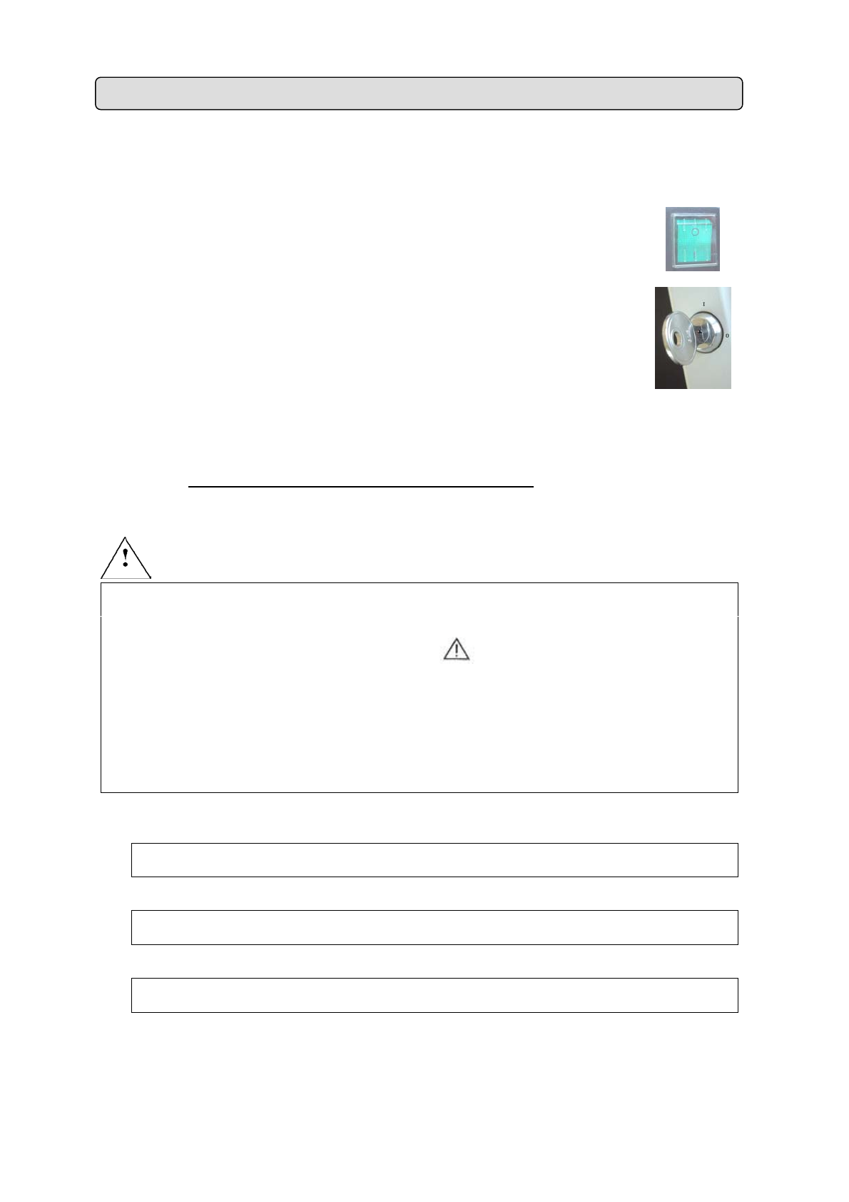
Here below is the suggested operative sequence for a correct exposure:
1. TURN ON THE TIMER to power the radiographic system
a.
Press the "MAIN SWITCH" located on the upper part of the timer to the
“I” position (ON)
b. Turn the “’KEY SWITCH” to the “I” position (ON)
Â
the green light turns on indicating that the system is powered up
Â
the Leds of the set x-ray parameters automatically light up
Â
the exposure time is shown on the display
c. THE RADIOGRAPHIC SYSTEM IS NOW READY FOR USE
CAUTION
If an error is detected when the system is turned on, the anomaly is indicated as follows:
•
an intermittent beep sounds
•
the “MALFUNCTIONING INDICATOR”
Led intermittently turns on
The error code (E ….) appears on the display
(refer to §12 “ERROR MESSAGES”)
•
All “Control Panel” functions are inhibited
In this case, turn off the timer and then turn it back on.
If the error should repeat itself, call Customer Support.
PLEASE NOTE
The exposure time and x-ray parameters which appear on the display are the last that were
set before the timer was turned off.
PLEASE NOTE
If installed, outside the office, the RX signaling lamp, corresponding to the selected
tubehead turns on.
PLEASE NOTE
If the timer remains inactive for a few minutes, it switches to stand-by mode.
Press any key on the “Control Panel” to restore it to operating mode.
6. USE INSTRUCTIONS
Page 16
2. CHECK THE SELECTED EXPOSURE PARAMETERS
Before making the exposure check that the “Control Panel” selected parameter
(from Step 1 to Step 6) are suitable for the x-ray exam.
STEP 1
Â
Check the selected tubehead
The Led of the desired tubehead should be turned on:
Led Rx1 ON
indicates that the tubehead connected to the timer XRAY1 terminal block is
selected
Led Rx2 ON
indicates that the tubehead connected to the timer XRAY2 terminal block is
selected
To change the selection press the button “RX”
STEP 2
Â
Check the selected tubehead type
The DC
Led should be lit
If the DC Led is not lit call Customer Support
STEP 3
Â
Check the selected x-ray distance
The
Led of the desired SSD should be lit
Led 12” SSD = 31 cm
Led 8” SSD = 20 cm
If Led is NOT lit call Customer Support
CAUTION
The assembled cone must be the cone corresponding to the selected SSD.
Page 17
STEP 4
Â
Check the selected x-ray technique
IF YOU ARE
WORKING WITH
CONVENTIONAL
FILMS
Check that the Led for the desired speed film is lit
Led “D” ON
indicates that the system is set for use with “D” speed film
Led “E” ON
indicates that the system is set for use with “E” speed film
Led “F” ON
indicates that the system is set for use with “F” speed film
To change the speed film, press “FILMTYPE” and keep it pressed
for 3 sec. until the beep sounds
PLEASE NOTE
After modification, default exposure values will be
automatically changed.
PLEASE NOTE
With conventional films it is advisable to use a x-ray of 8mA
(see STEP 7)
IF YOU ARE
WORKING WITH
A DIGITAL
ACQUISITION
SYSTEM
(CCD OR
EQUIVALENT)
Check that the Led is lit
To change the speed film, press “DIGIT” and keep it pressed for
3 sec. until the beep sounds
PLEASE NOTE
After modification, default exposure values will be
automatically changed.
PLEASE NOTE
With the sensor it is advisable to use a stet current of 4mA (see
STEP 7)
Page 18
STEP 5
Â
Check the selected patient type
The
desired patient led of the should be lit
Led Child ON
indicates that the system is set for a patient with a small physique
Led Adult ON
indicates that the System is set for a patient with a large physique
To change the selection press the button located between the two icons
“CHILD/ADULT”.
PLEASE NOTE
After modification, default exposure values will be automatically changed.
STEP 6
Â
Check the selected x-ray voltage
The
Led of the desired voltage should be lit
Led 60 kV ON
indicates that the system is set with the “HIGT CONTRAST” radiodiagnostic
technology
Led 70 kV ON
indicates that the system is set with the “LOW CONTRAST” radiodiagnostic
technology
To change the selection press the “kV” button
PLEASE NOTE
After modification, default exposure values will be automatically changed.
STEP 7
Â
Check the selected x-ray current
The
desired current led of the should be lit
Led 8 mA ON
indicates that the system is set for “NOMINAL DOSE”.
The use of “CONVENTIONAL FILMS (FILM)” is advisable
Led 4 mA ON
indicates that the system is set for “REDUCED DOSE”.
The use of “DIGITAL SYSTEMS (FILM)” is advisable
Page 19

To change the selection press the “mA” button
PLEASE NOTE
After modification, default exposure values will be automatically changed.
Page 20
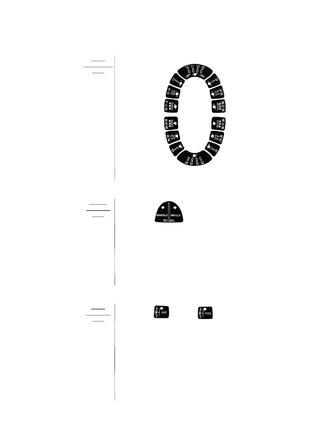
STEP 8
Â
Check the intra-oral test selected
FOR A
PERIPERICAL
EXAM
The Led for the desired tooth must be on
To change the selection, press the key for the desired tooth
FOR AN
OCCLUSAL
EXAM
Check that the Led is lit
MANDIBULA Led ON
indicates that the system is set for the OCCLUSAL exam of the
LOWER JAW
MAXILLA Led ON
indicates that the system is set for the OCCLUSAL exam of the
UPPER JAW
To change the selection, press the “OCCLUSAL”
FOR A
BITE-WING
EXAM
Check that the Led or the Led is lit.
ANT Led ON
indicates that the system is set for the exposure time needed for
the FRONT BITE-WING EXAM
POST Led ON
indicates that the system is set for the exposure time needed for
the BACK BITE-WING EXAM
To change the selection, press the key of the desired
“BITE-WING” exam
Page 21
3. POSITIONING THE PATIENT
Following the standard intra-oral procedures:
−
position the patient
−
positionthe patient’s head
4. POSITIONING THE FILM/SENSOR
Position either the “FILM” or the “DIGITAL SENSOR” depending on the technique to be used:
−
bisecting angle technique or short (8”) cone technique
−
parallel technique or long (12”) cone technique
5. POSITIONING THE CONE
Following the standard positioning procedures bring the cone of the tubehead towards the
patient and precisely in the direction of the film or digital sensor
PLEASE NOTE
To correctly orient the cone it is advisable to use the graduated scale indicated on the
tubehead.
6. CHECK ON THE SELECTED TIME DISPLAY
Before proceeding with the exposure, check on the selected time display
To modify, use the
key or the key
WARNING
This modification at the exposure time is momentary and will be lost unless it is saved. (refer to
§9 “PROGRAMMING DEFAULT EXPOSURE VALUES”)
PLEASE NOTE
To restore the previous values, press one of the keys with the led turned off on the “Control
Panel”.
Page 22
7. MAKING THE EXPOSURE
Now that the exposure parameters are optimal, the exposure may be made.
1. Take the “CONTROL BUTTON” of the timer
WARNING
If “CONTROL BUTTON” N.2 (optional) is installed:
Ö
use “CONTROL BUTTON” n° 1 for tube head 1 (Rx1)
Ö
use “CONTROL BUTTON” n° 2 for tube head 2 (Rx2)
2. Using the extendable cable of the “CONTROL BUTTON” to maintain a buffer zone of 2
meters from the tube head and be able to constantly check the radiological exposure
3. Advise the patient to remain still
4.
Press the key
“X-RAY” and keep it pressed until the acoustic signal (beep) stops
and the yellow “X-RAY OUTPUT SIGNAL”
Led turns off
PLEASE NOTE
If the “X-RAY” key is released early, the exposure is immediately interrupted and the E12
error message appears on the display.
8. THE END OF EXPOSURE
At the end of the exposure:
a. the green “PAUSE INDICATOR”
Led indicates the pause period
b. the display indicates the actual duration of the exposure
c. all the timer functions are inhibited
PLEASE NOTE
The pause time is necessary to allow the X-ray tube to cool down.
This time is calculated by the microprocessor, depending on the exposure time, with a ratio
of 1:32 (32 seconds of pause are required for each second of exposure).
A NEW EXPOSURE WILL BE POSSIBLE AFTER THE GREEN LED HAS TURNED OFF
(REPEAT THE OPERATIVE SEQUENCE FROM POINT 2 TO POINT 8)
Page 23
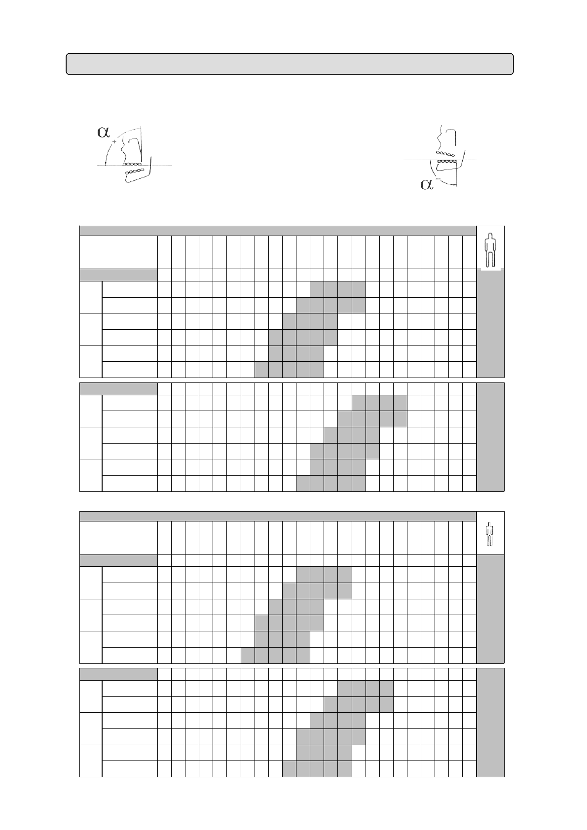
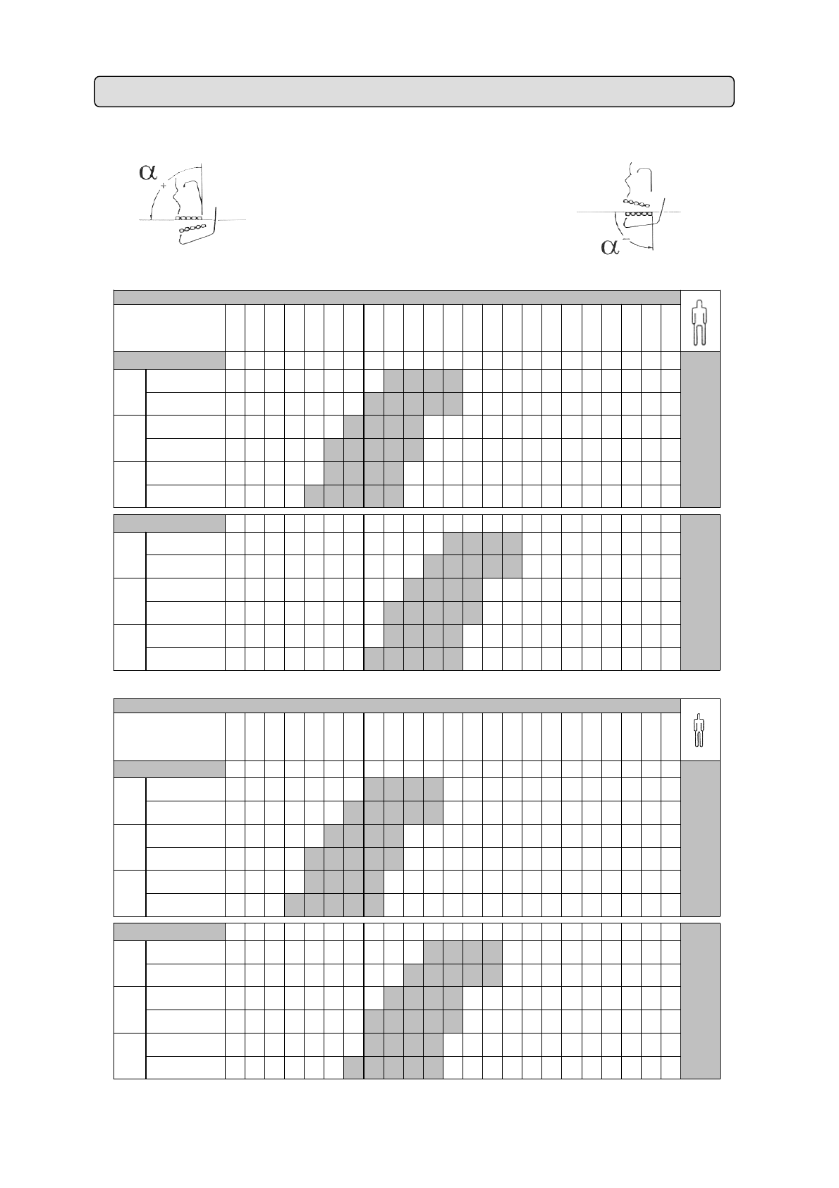
The chart indicates the “X-Mind
®
DC” X-ray system’s predefined exposure values
(refer to §5: “SYSTEM CONFIGURATION”)
12” CONE
(SSD = 31 cm)
Ö CONVENTIONAL X-RAY TECHNIQUE (FILM)
7. CHART OF DEFAULT EXPOSURE VALUES FOR THE 12” CONE
0.020s
0.025s
0.032s
0.040s
0.050s
0.063s
0.080s
0.100s
0.125s
0.160s
0.200s
0.250s
0.320s
0.400s
0.500s
0.630s
0.800s
1.000s
1.250s
1.600s
2.000s
2.500s
3.200s
I
CP
Bp
MOp
I
CP
Ba
M-Oa
I
CP
Bp
MOp
I
CP
Ba
M-Oa
I
CP
Bp
MOp
I
CP
Ba
M-Oa
I
CP
Bp
MOp
I
CP
Ba
M-Oa
I
CP
Bp
MOp
I
CP
Ba
M-Oa
I
CP
Bp
MOp
I
CP
Ba
M-Oa
0.020s
0.025s
0.032s
0.040s
0.050s
0.063s
0.080s
0.100s
0.125s
0.160s
0.200s
0.250s
0.320s
0.400s
0.500s
0.630s
0.800s
1.000s
1.250s
1.600s
2.000s
2.500s
3.200s
I
C P
Bp
MOp
I
C P
Ba
M-Oa
I
C P
Bp
MOp
I
C P
Ba
M-Oa
I
C P
Bp
MOp
I
C P
Ba
M-Oa
I
C P
Bp
MOp
I
C P
Ba
M-Oa
I
CP
Bp
MOp
I
C P
Ba
M-Oa
I
C P
Bp
MOp
I
C P
Ba
M-Oa
60kV - 8mA
FILM
F
MAXILLA
70kV - 8mA
MAXILLA
MANDIBLE
MANDIBLE
60kV - 8mA
MAXILLA
MANDIBLE
FILM
F
MAXILLA
MANDIBLE
FILM
E
60kV - 8mA
MAXILLA
FILM
D
MANDIBLE
MANDIBLE
FILM
E
MAXILLA
MANDIBLE
MAXILLA
FILM
D
FILM
F
MAXILLA
MANDIBLE
60kV - 8mA
FILM
D
MAXILLA
MANDIBLE
A
DUL
T
PROGRAMMED
EXPOSURE TIMES
(sec)
70kV - 8mA
70kV - 8mA
MAXILLA
MANDIBLE
FILM
E
MAXILLA
MANDIBLE
CHILD
PROGRAMMED
EXPOSURE TIMES
(sec)
FILM
F
FILM
D
70kV - 8mA
MAXILLA
FILM
E
MANDIBLE
Page 24
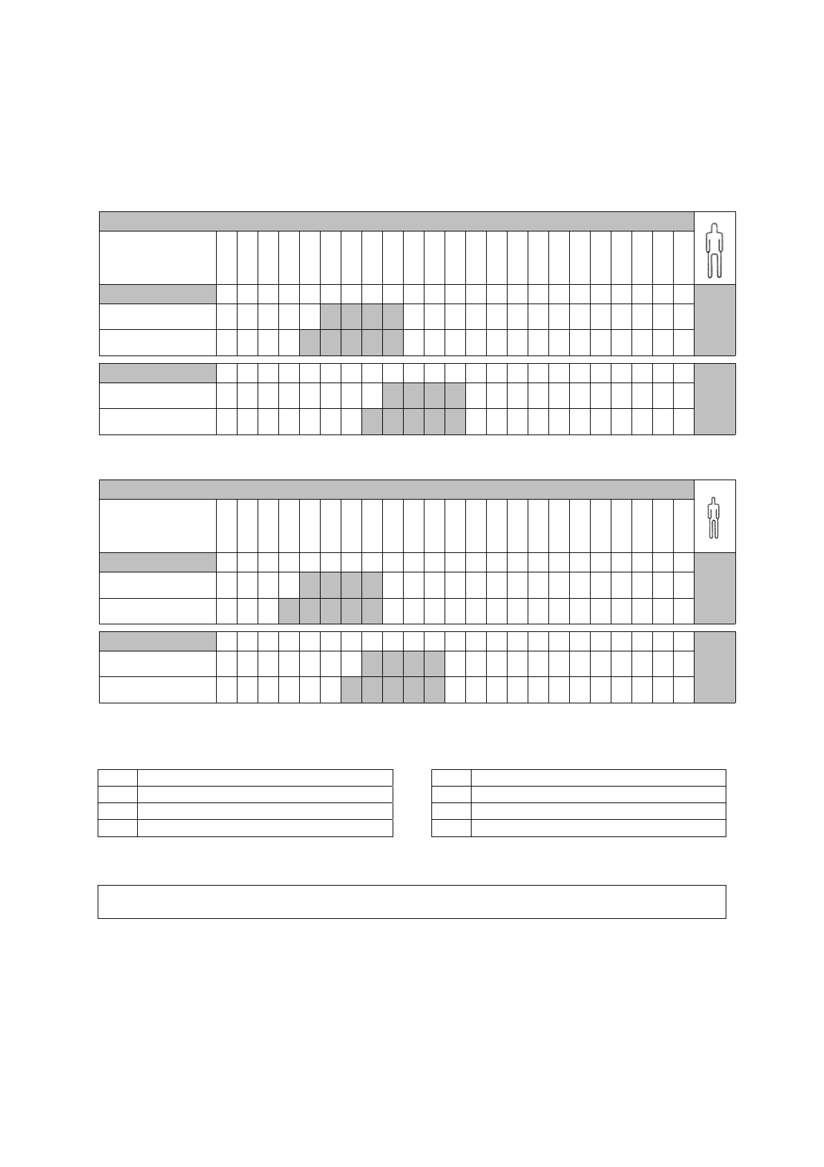
Ö DIGITAL X-RAY TECHNIQUE (CCD or similar)
0.020s
0.025s
0.032s
0.040s
0.050s
0.063s
0.080s
0.100s
0.125s
0.160s
0.200s
0.250s
0.320s
0.400s
0.500s
0.630s
0.800s
1.000s
1.250s
1.600s
2.000s
2.500s
3.200s
I
C P
Bp
MOp
I
C P
Ba
M-Oa
I
C P
Bp
MOp
I
C P
Ba
M-Oa
0.020s
0.025s
0.032s
0.040s
0.050s
0.063s
0.080s
0.100s
0.125s
0.160s
0.200s
0.250s
0.320s
0.400s
0.500s
0.630s
0.800s
1.000s
1.250s
1.600s
2.000s
2.500s
3.200s
I
C P
Bp
MOp
I
C P
Ba
M-Oa
I
C P
Bp
MOp
I
C P
Ba
M-Oa
MANDIBLE
CHILD
PROGRAMMED
EXPOSURE TIMES
(sec)
60kV - 4mA
MANDIBLE
70kV - 4mA60kV - 4mA
MANDIBLE
MAXILLA
MAXILLA
ADULT
PROGRAMMED
EXPOSURE TIMES
(sec)
70kV - 4mA60kV - 4mA
70kV - 4mA
MAXILLA
70kV - 4mA
MAXILLA
MANDIBLE
60kV - 4mA
LEGEND
I INCISOR Ba ANTERIOR BITE-WING
C CANINE Bp POSTERIOR BITE-WING
P PREMOLAR Oa ANTERIOR MANDIBLE OCCLUSAL
M MOLAR Op POSTERIOR MANDIBLE OCCLUSAL
PLEASE NOTE
To modify the default exposure times.
(refer to § 9: “PROGRAMMING DEFAULT EXPOSURE VALUES”)
Page 25
The chart indicates the “X-Mind
®
DC” X-ray system’s predefined exposure values
(refer to § 5 “SYSTEM CONFIGURATION”)
8” CONE
(SSD = 20 cm)
NOT AVAILABLE IN U.K.
Ö CONVENTIONAL X-RAY TECHNIQUE (FILM)
8. CHART OF DEFAULT EXPOSURE VALUES FOR THE 8” CONE
0.020s
0.025s
0.032s
0.040s
0.050s
0.063s
0.080s
0.100s
0.125s
0.160s
0.200s
0.250s
0.320s
0.400s
0.500s
0.630s
0.800s
1.000s
1.250s
1.600s
2.000s
2.500s
3.200s
I
C P
Bp
MOp
I
C P
Ba
M-Oa
I
C P
Bp
MOp
I
C P
Ba
M-Oa
I
C P
Bp
MOp
I
C P
Ba
M-Oa
I
C P
Bp
MOp
I
C P
Ba
M-Oa
I
C P
Bp
MOp
I
C P
Ba
M-Oa
I
C P
Bp
MOp
I
C P
Ba
M-Oa
0.020s
0.025s
0.032s
0.040s
0.050s
0.063s
0.080s
0.100s
0.125s
0.160s
0.200s
0.250s
0.320s
0.400s
0.500s
0.630s
0.800s
1.000s
1.250s
1.600s
2.000s
2.500s
3.200s
I
C P
Bp
MOp
I
C P
Ba
M-Oa
I
C P
Bp
MOp
I
C P
Ba
M-Oa
I
C P
Bp
MOp
I
C P
Ba
M-Oa
I
C P
Bp
MOp
I
C P
Ba
M-Oa
I
C P
Bp
MOp
I
C P
Ba
M-Oa
I
C P
Bp
MOp
I
C P
Ba
M-Oa
A
DUL
T
PROGRAMMED
EXPOSURE TIMES
(sec)
70kV - 8mA
70kV - 8mA
MANDIBLE
FILM
E
MAXILLA
MANDIBLE
MAXILLA
CHILD
PROGRAMMED
EXPOSURE TIMES
(sec)
MANDIBLE
MANDIBLE
FILM
E
MAXILLA
MANDIBLE
60kV - 8mA
FILM
D
FILM
F
MAXILLA
FILM
F
FILM
D
70kV - 8mA
MAXILLA
MAXILLA
MANDIBLE
MAXILLA
FILM
D
MANDIBLE
60kV - 8mA
FILM
D
MAXILLA
MANDIBLE
MANDIBLE
FILM
F
MAXILLA
MANDIBLE
FILM
E
60kV - 8mA
FILM
F
MAXILLA
70kV - 8mA
MAXILLA
MANDIBLE
MANDIBLE
60kV - 8mA
MAXILLA
FILM
E
Page 26
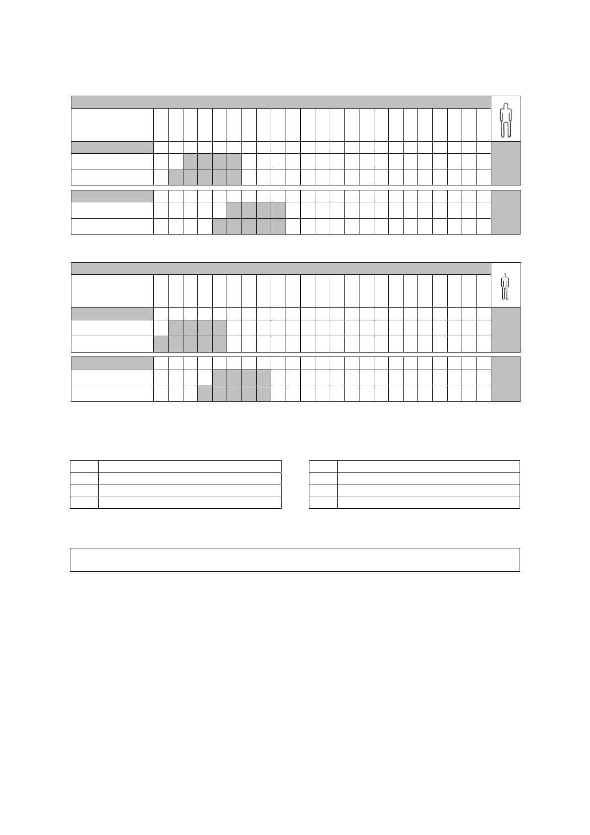
Ö DIGITAL X-RAY TECHNIQUE (CCD or similar)
0.020s
0.025s
0.032s
0.040s
0.050s
0.063s
0.080s
0.100s
0.125s
0.160s
0.200s
0.250s
0.320s
0.400s
0.500s
0.630s
0.800s
1.000s
1.250s
1.600s
2.000s
2.500s
3.200s
I
C P
Bp
MOp
I
C P
Ba
M-Oa
I
C P
Bp
MOp
I
C P
Ba
M-Oa
0.020s
0.025s
0.032s
0.040s
0.050s
0.063s
0.080s
0.100s
0.125s
0.160s
0.200s
0.250s
0.320s
0.400s
0.500s
0.630s
0.800s
1.000s
1.250s
1.600s
2.000s
2.500s
3.200s
I
C P
Bp
MOp
I
C P
Ba
M-Oa
I
C P
Bp
MOp
I
C P
Ba
M-Oa
60kV - 4mA
70kV - 4mA60kV - 4mA
MAXILLA
MANDIBLE
MANDIBLE
70kV - 4mA
MAXILLA
CHILD
PROGRAMMED
EXPOSURE TIMES
(sec)
60kV - 4mA
MANDIBLE
MAXILLA
60kV - 4mA
ADULT
PROGRAMMED
EXPOSURE TIMES
(sec)
70kV - 4mA
70kV - 4mA
MAXILLA
MANDIBLE
LEGEND
I INCISOR Ba ANTERIOR BITE-WING
C CANINE Bp POSTERIOR BITE-WING
P PREMOLAR Oa ANTERIOR MANDIBLE OCCLUSAL
M MOLAR Op POSTERIOR MANDIBLE OCCLUSAL
PLEASE NOTE
To modify the default exposure times.
(refer to § 9“ PROGRAMMING DEFAULT EXPOSURE VALUES”)
Page 27
WARNING
The 17 programmed exposure times (refer to § 5.B “SYSTEM CONFIGURATION”)
M
AY NO
T
be
modified in the “X-Mind
®
DC” X-ray system, you may, however, customize the default exposure
values (refer to § 5.C “SYSTEM CONFIGURATION”)
WARNING
After customizing, the “Chart of default exposure values” (refer to § 7 “CHART OF DEFAUL
T
EXPOSURE VALUES FOR THE 12” CONE” and § 8 “CHART OF DEFAULT EXPOSURE VALUES FOR TH
E
8” CONE”) ARE NO LONGER VALID .
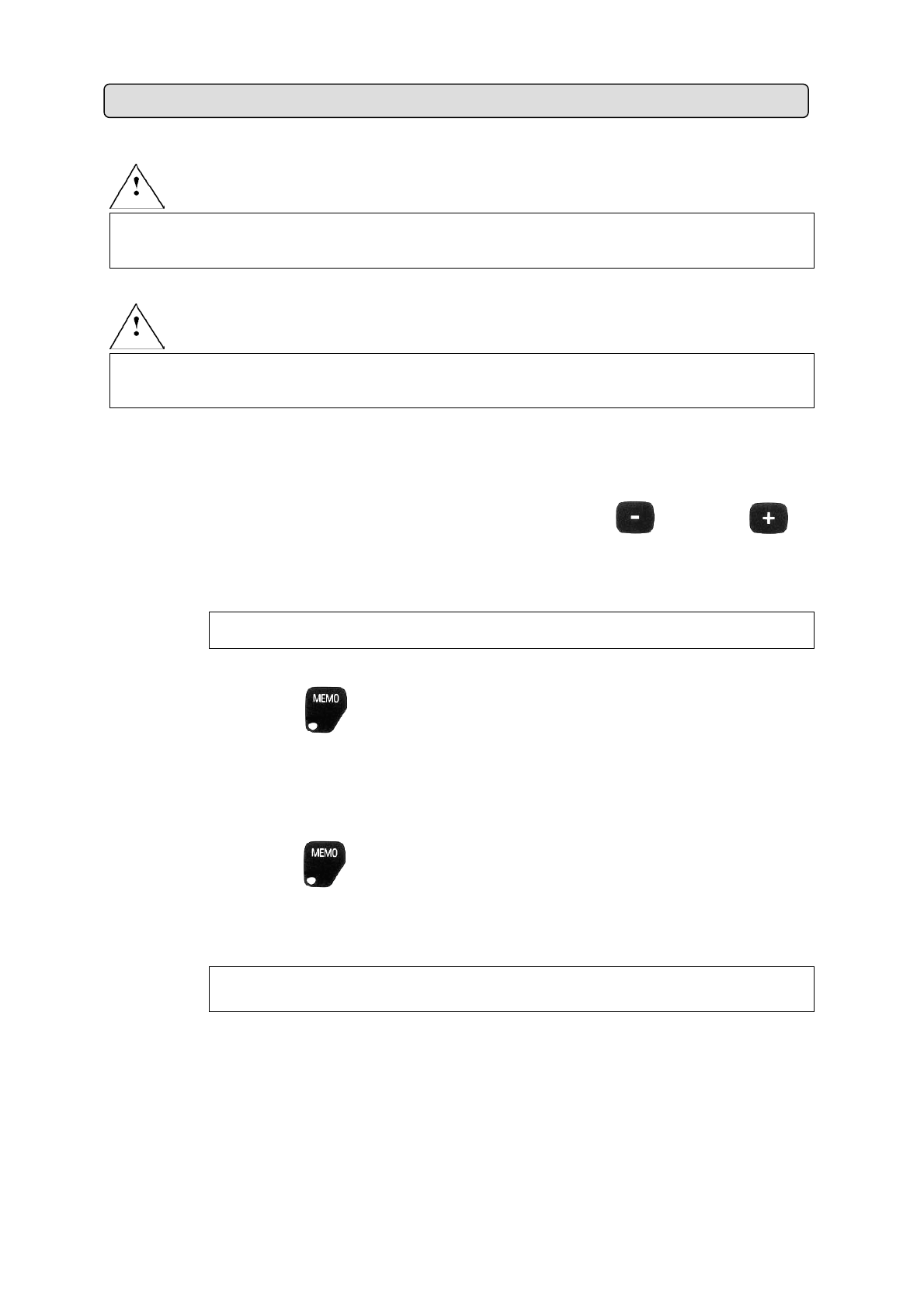
To program the new exposure values, proceed as follows:
1.
Modify the exposure time on the display by pressing the
key or the
key
PLEASE NOTE
The “repeat” function automatically activates when the key is kept depressed,
allowing the time shown on the display to scroll faster.
2.
Check the
Led
When the MEMO Led is OFF, it is NOT possible to save data
When the MEMO Led is lit, it is possible to save data
3.
Press the
key and keep it depressed for 3 seconds until the acoustic signal
sounds to save the new default exposure values
PLEASE NOTE
It is NOT possible to save data when the “range of exposure field” exceeds the
programmed exposure time limits (refer to the example on the next page).
9. PROGRAMMING DEFAULT EXPOSURE VALUES
Page 28
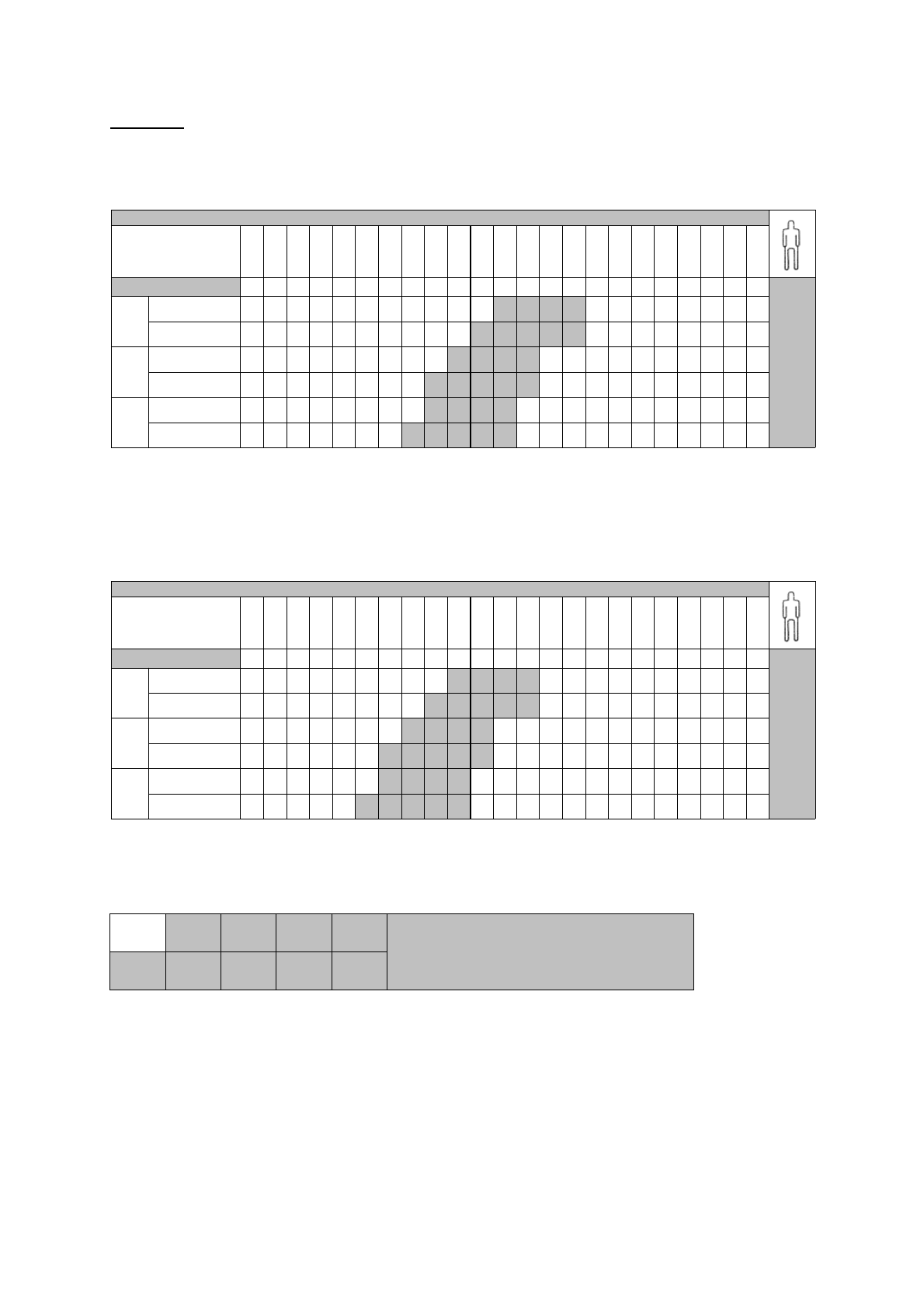
Example:
Ö PREDEFINED EXPOSURE VALUES
0.020s
0.025s
0.032s
0.040s
0.050s
0.063s
0.080s
0.100s
0.125s
0.160s
0.200s
0.250s
0.320s
0.400s
0.500s
0.630s
0.800s
1.000s
1.250s
1.600s
2.000s
2.500s
3.200s
I
C P
Bp
MOp
I
C P
Ba
M-Oa
I
C P
Bp
MOp
I
C P
Ba
M-Oa
I
C P
Bp
MOp
I
C P
Ba
M-Oa
70kV - 8mA
MANDIBLE
FILM
E
MAXILLA
MANDIBLE
FILM
D
A
DULT
PROGRAMMED
EXPOSURE TIMES
(sec)
70kV - 8mA
MAXILLA
FILM
F
MAXILLA
MANDIBLE
Ö CUSTOMIZED DEFAULT EXPOSURE VALUES
(The range of exposure entered has been reduced by two steps)
0.020s
0.025s
0.032s
0.040s
0.050s
0.063s
0.080s
0.100s
0.125s
0.160s
0.200s
0.250s
0.320s
0.400s
0.500s
0.630s
0.800s
1.000s
1.250s
1.600s
2.000s
2.500s
3.200s
I
C P
Bp
MOp
I
C P
Ba
M-Oa
I
C P
Bp
MOp
I
C P
Ba
M-Oa
I
C P
Bp
MOp
I
C P
Ba
M-Oa
A
DULT
PROGRAMMED
EXPOSURE TIMES
(sec)
FILM
D
MAXILLA
MANDIBLE
70kV - 8mA
70kV - 8mA
FILM
E
MAXILLA
MANDIBLE
FILM
F
MAXILLA
MANDIBLE
I
C P
Bp
M Op
I
C P
Ba
M - Oa
RANGE OF EXPOSURE FIELD
Page 29
To restore factory settings, proceed as follows:
1. Turn the timer off
2. While keeping the
key depressed and turn on the timer
3. OFF will appear on the display
4. Release the
key
5. Press the
key again
6. ON will appear on the display
7.
Turning the timer on and off will restore the factory settings
10. RESTORING ORIGINAL VALUES
Page 30
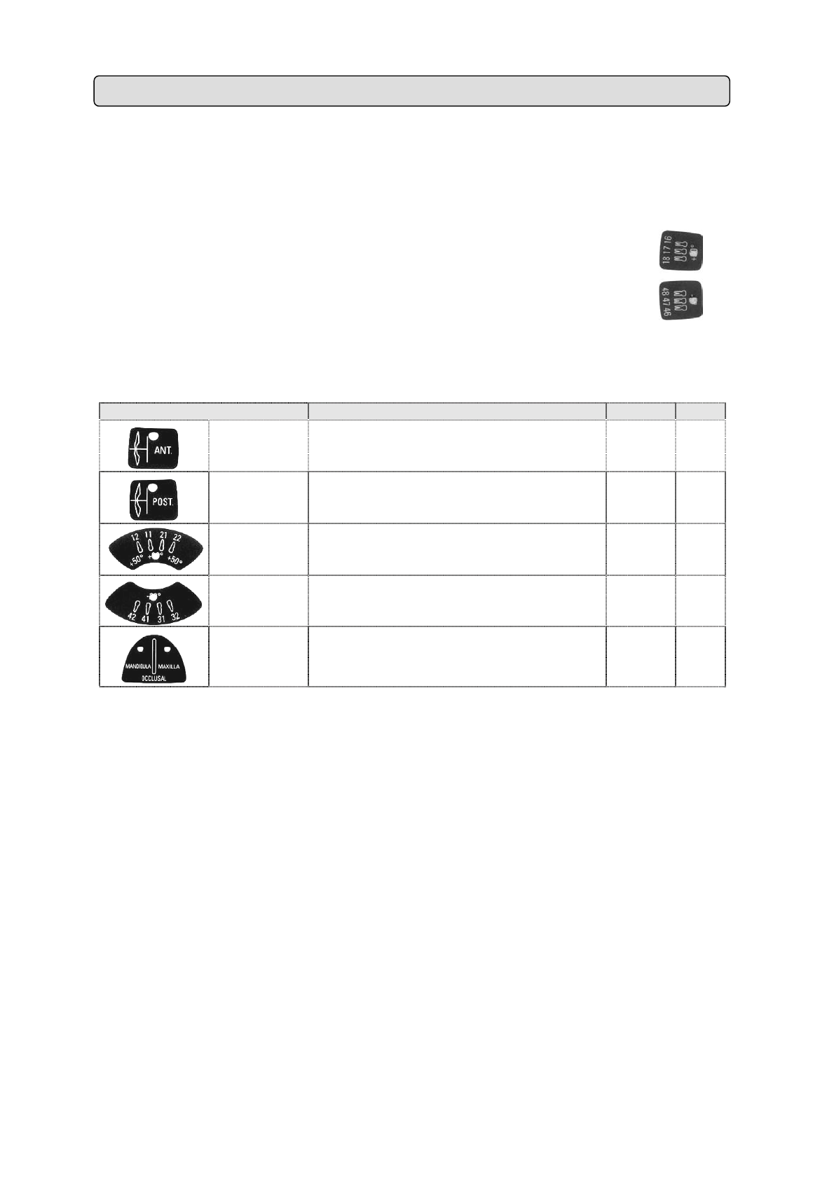
The “X-Mind
®
DC” X-ray system allows the user to display certain functional parameters.
To display them, proceed as follows:
a. Simultaneously press and keep pressing the keys marked
(17) MAXILLA MOLAR + (47) MANDIBLE MOLAR
b. Press the key associated with the parameter one wishes to view:
KEY DISPLAYED PARAMETER Example M.U.
BITE-WING
ANT
X-RAY SYSTEM
NOMINAL VOLTAGE
230 Volt
BITE-WING
POST
LINE VOLTAGE 227 Volt
UPPER
INCISOR
MAXIMUM LINE VOLTAGE
VALUE DETECTED
238 Volt
LOWER
INCISOR
MINIMUM LINE VOLTAGE
VALUE DETECTED
215 Volt
OCCLUSAL SOFTWARE VERSION 2.3
11. DIAGNOSTICS
Page 31
The following chart gives a list of error messages that may appear while the “X-Mind
®
DC” X-ray
system is in operation.
The chart also includes the causes of the error messages and what to do to resolve them.
Error
Message
Cause Solution
RX1 TUBEHEAD
IS NOT CONNECTED OR IS OUT OF ORDER
CALL THE “SUPPORT DEPARTMENT”
RX2 TUBEHEAD
IS NOT CONNECTED OR IS OUT OF ORDER
CALL THE “SUPPORT DEPARTMENT”
CORRUPTED EEPROM DATA CALL THE “SUPPORT DEPARTMENT”
EEPROM DATA NOT SAVED PROPERLY CALL THE “SUPPORT DEPARTMENT”
LINE VOLTAGE VALUE NOT WITHIN SET
LIMITS
CALL THE “SUPPORT DEPARTMENT”
LINE VOLTAGE VALUE NOT WITHIN THE ±
15% NOMINAL VALUE
CALL THE “SUPPORT DEPARTMENT”
THE “X-RAY” KEY
ALWAYS SEEMS TO BE PRESSED
ENSURE IT IS NOT JAMMED
ANOMALY IN THE CONTROL PANEL CALL THE “SUPPORT DEPARTMENT”
THE EXPOSURE
HAS BEEN PREMATURELY INTERRUPTED
KEEP THE “X-RAY KEY”
PRESSED UNTIL THE END OF THE EXPOSURE
ANOMALY IN THE TRIAC/RELAY CALL THE “SUPPORT DEPARTMENT”
ANOMALY IN THE ELECTRONIC CIRCUIT CALL THE “SUPPORT DEPARTMENT”
ANOMALY IN THE CONTROL CIRCUIT CALL THE “SUPPORT DEPARTMENT”
INCORRECT DIP-SWITCH CONFIGURATION CALL THE “SUPPORT DEPARTMENT”
THE “CONTROL BUTTON” DOES NOT
CORRESPOND TO THE SELECTED TUBEHEAD
SELECT THE “CONTROL BUTTON” THAT CORRESPONDS
TO THE SELECTED TUBEHEAD
THE TUBEHEAD
DOES NOT WORK PROPERLY
CALL THE “SUPPORT DEPARTMENT”
THE TUBEHEAD
IS NOT IN THE CORRECT MODE
CALL THE “SUPPORT DEPARTMENT”
12. ERROR MESSAGES
Page 32
THE TUBEHEAD
HAS NOT COMPLETED THE EXPOSURE
REPEAT THE EXPOSURE OR
CALL THE “SUPPORT DEPARTMENT”
PROBLEM IN THE FREQUENCY
OR REGULATION
CALL THE “SUPPORT DEPARTMENT”
THE TUBEHEAD
IS NOT CALIBRATED
CALIBRATE THE TUBEHEAD OR
CALL THE “SUPPORT DEPARTMENT”
EEPROM DATA NOT SAVED PROPERLY CALL THE “SUPPORT DEPARTMENT”
CORRUPTED EEPROM DATA CALL THE “SUPPORT DEPARTMENT”
OVERVOLTAGE ERROR CALL THE “SUPPORT DEPARTMENT”
ANODE VOLTAGE OUT OF TOLERANCE CALL THE “SUPPORT DEPARTMENT”
ANODE CURRENT OUT OF TOLERANCE CALL THE “SUPPORT DEPARTMENT”
CONTROL CONNECTOR CALL THE “SUPPORT DEPARTMENT”
PROBLEM IN THE REFERENCE VOLTAGE CALL THE “SUPPORT DEPARTMENT”
MAJOR ERROR
ALL X-RAY SYSTEM FUNCTIONS ARE DISABLED
CALL THE “SUPPORT DEPARTMENT”
Page 33

POWER SUPPLY CHARACTERISTICS
♦
TYPE OF POWER SUPPLY at constant potential
♦
NOMINAL VOLTAGE 230 V 115 V
♦
MAXIMUM VOLTAGE VARIATION
±
15 % ± 15 %
♦
NOMINAL CURRENT
6A 12 A
♦
FREQUENCY 50/60Hz 50/60Hz
♦
POWER EMITTED
1.4 kVA 1.4 kVA
♦
APPARENT LINE RESISTANCE
0.5 Ω 0.2 Ω
♦
PROTECTIVE FUSES
(F1 – F2 – F3 – F4) (quick fuse)
8AF – 250 V 12..5AF – 250 V
♦
(F5)
n° 1 mini-fuse 630 mA to 125V axial
CIRCUIT PROTECTIVE FUSES
(LOCATED ON THE SECONDARY OF THE
(F6)
n° 1 mini-fuse 500 mA to 125V axial
X-RAY SYSTEM - TECHNICAL DATA
♦
GENERATO
R
at constant potential at 200 kHz frequency
♦
HIGH NOMINAL VOLTAGE 60 kV – 70 kV
♦
NOMINAL CURRENT 4 mA – 8 mA
♦
NOMINAL ELECTRIC POWER AT 0...1 sec
560 W 70 kV 8 mA
480 W 60 kV 8 mA
280 W 70 kV 4 mA
240 W 60 kV 4 mA
♦
REFERENCE CURRENT-TIME PRODUCT
0.8 mAs 8 mA 0.1 sec
0.4 mAs 4 mA 0.1 sec
♦
INTENSITY OF RADIATION IN THE AI
R
>30 µGy/h at 1 meter away from focal spot
♦
TOTAL FILTRATION equivalent to 2 mm Al at 70kV
♦
HALF VALUE LAYER (HVL) AT 70 kV > 1.6 mm Al
♦
RADIATION LEAKAGE less than 0..25 mGy/h at 1 meter from focal spot
♦
LINEARITY 10 %
♦
REPRODUCIBILITY 0.05
♦
ELECTRICAL CLASSIFICATION Class “I” – Type “B” – Intermittent Service
13. SYSTEM TECHNICAL DATA
Page 34
MEASUREMENT CONDITIONS
♦
kVp non-invasive measurement
♦
mAs direct measurement with digital instrument
♦
EXPOSURE TIME (sec) “non-invasive” measurement with digital
ACCURACY OF TECHNICAL DATA
♦
NOMINAL VOLTAGE OF X-RAY TUBE
± 10 %
♦
NOMINAL CURRENT OF THE X-RAY TUBE
± 10 %
♦
SELECTED EXPOSURE TIME
± 0.005 from 0.020 to 0.1 sec
± 5 from 0.125 to 3.2 sec
WEIGHT
♦
TOTAL WEIGHT 25 Kg.
♦
WEIGHT OF TUBEHEAD 5.5 Kg.
ENVIRONMENTAL CHARACTERISTICS
♦
OPERATING TEMPERATURE
+5°C +40°C
♦
WAREHOUSE TEMPERATURE
-15°C +50°C
♦
HUMIDITY
25 % - 75 %
TECHNICAL CONE DATA
SOURCE-SKIN DISTANCE (SSD)
SHORT 8” CONE 20 cm (8”)
LONG 12” CONE 31 cm (12”)
♦
RECTANGULAR CONE 31 cm (12” )
♦
DIAMETER OF X-RAY BEAM
WITH 8” OR 12” CONE
≤
60 mm
WITH RECTANGULAR CONE 44x35 mm
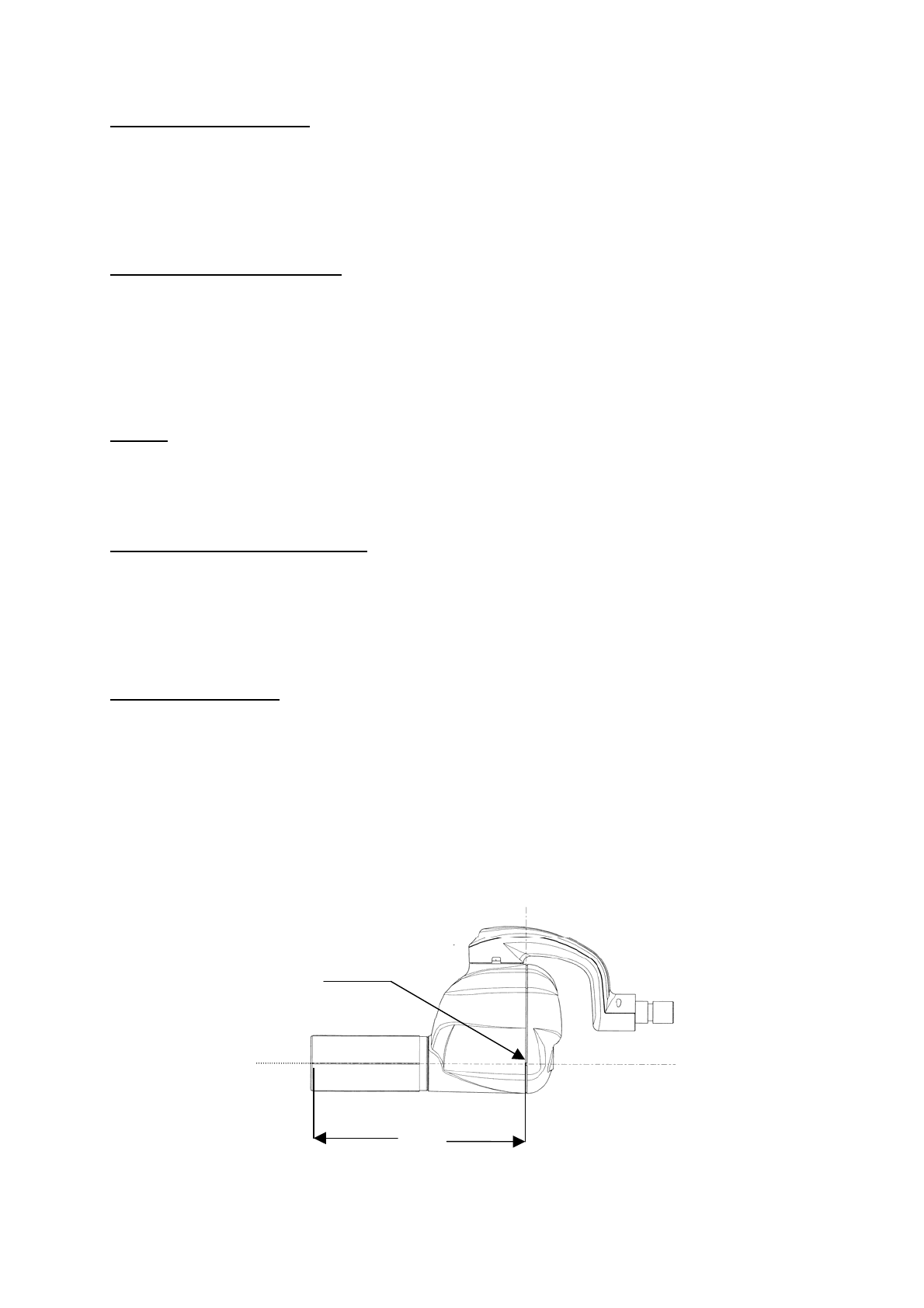
SSD (SOURCE-SKIN DISTANCE) = 31 cm (12”) to 20 cm (8”)
Identification of the focal
SSD
Reference Axis
Page 35
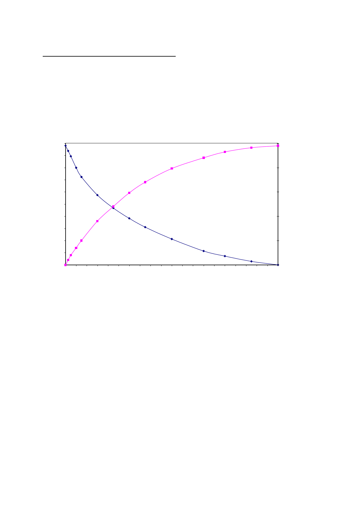
THERMAL CHARACTERISTICS OF THE TUBEHEAD
♦
TUBEHEAD’S HEAT ACCUMULATION CAPACITY
140 kJ (196 kHU)
♦
MAXIMUM COOLING SPEED
1.2 kJ/min (1.8 kHU/min)
HEATING AND COOLING CURVES
0
20
40
60
80
100
120
140
160
180
200
0 20 40 60 80 100 120 140 160 180 200 220 240 260 280 300 320 340 360 380 400
Time (min)
kHT
21
26
31
36
41
46
°C
cooling, 21°C
heating, 21°C
HEAT CAPACITY
kHU
Page 36
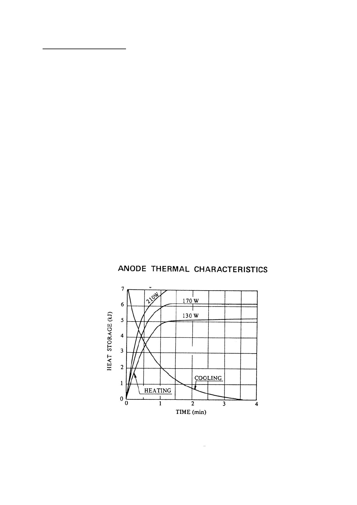
X-RAY TUBE TECHNICAL DATA
♦
X-RAY TUBE TOSHIBA DG-073B-DC
♦
SIZE OF FOCAL SPOT 0.7 - (IEC 336/1993)compliant
♦
NOMINAL ANODE VOLTAGE 70 kV
♦
NOMINAL ANODE CURRENT 8 mA
♦
NOMINAL ANODE POWER 560 W
(70 kV – 8 mA – form factor = 1)
♦
EXPOSURE TIME
0.08
÷
3.2 sec in 17 steps
♦
NOMINAL HIGH VOLTAGE
AND MAXIMUM CURRENT
70kV – 8 mA ±10 %
♦
TUBE INHERENT FILTRATION equivalent to 0.8 mm Al
♦
ANODE MATERIAL tungsten
♦
ANODE INCLINATION 20°
♦
ANODE HEAT LOAD 7 KJ (10 kHU)
♦
MAXIMUM CONTINUOUS HEAT
17.5 W
♦
OPERATING CYCLE 1:32
Page 37
In order to guarantee the safety of the X-ray system. a maintenance schedule must be set up.
The owner is responsible for setting up and adhering to a schedule for maintenance which must
be executed by qualified technicians who are able to certify their work with a “Compliance
Declaration”.
CAUTION
Run a check on the system and its operation when it is installed and every twelve months
thereafter.
Once a year, lubricate the pins and bushes of the wall plate and positioning arm, as specified
(refer to INSTALLATION & MAINTENANCE MANUAL §15 “MAINTENANCE”)
WARNING
Do not lose the adjustment key that comes with the system, since, in time, it might become
necessary to make readjustments.
WARNING
If parts become hard to move or squeak, call “Customer Support”.
14. SUGGESTED MAINTENANCE
Page 38
Use a damp soft cloth and soapy water to clean the outer surfaces.
The spacer cone may be cleaned with cotton wool and surgical alcohol.
In the event of a malfunction, send the defective part (IN THE ORIGINAL PACKAGING) to:
Satelec
S.A.S.
Z.I. du Phare
B.P. 216
33708 MERIGNAC cedex - France
Tel. +33 (0) 556 34 06 07
Fax +33 (0) 556 34 92 92
E-mail: [email protected]
The components and packaging must not be disposed of in a manner which is environmentally
harmful.
In particular, the dielectric oil as well as the shielding lead must be disposed of by specialized
companies which are authorized to deal with the disposal of waste material.
15. CLEANING THE OUTER SURFACES
16. IF A REPAIR BECOMES NECESSARY
17. DISPOSAL
Page 39
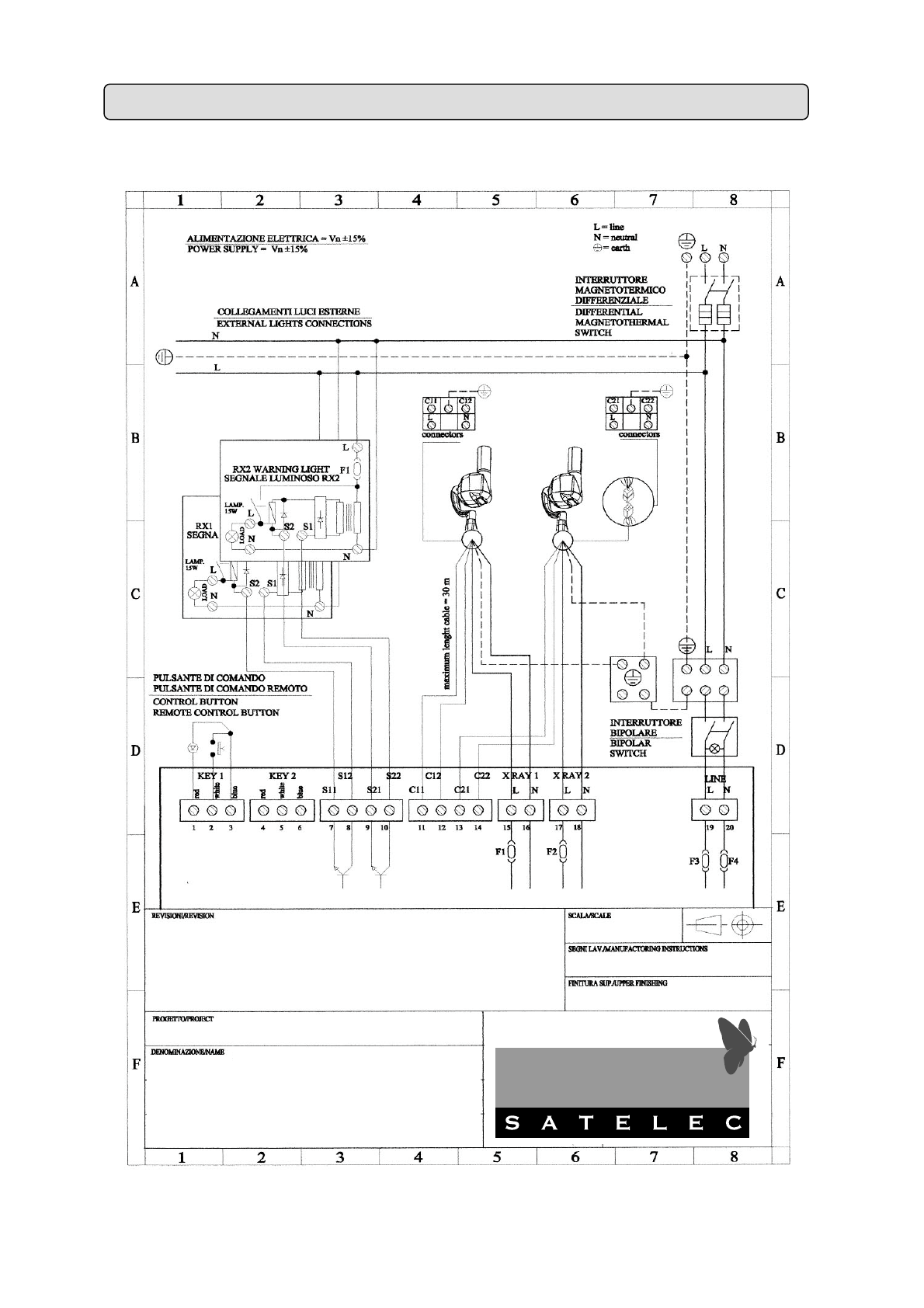
The manufacturer undertakes to supply, upon request, drawings, circuit diagrams, component parts
lists, instructions or other information needed by qualified technical personnel to perform repairs
on those parts of the “X-Mind
®
DC” X-ray system which may be repaired.
18. ACCESSORIES
X-Mind
®
DC
Installation electrical scheme
All rights reserved
 Loading...