

Page 1

Installation and Operation Manual
arium 611VF
Water Purification System
85030-513-68
Page 2

2
About This Manual
Safety Information 3
Intended Usage 4
Product Description 5
arium Systems 5
Control Panel and Display 6
Unpacking and Installation 8
Unpacking 8
Display|Dispenser Unit Installation 8
Ultrafilter Installation 10
Bench Mounting 11
Wall Mounting 11
Water Inlet Connection 12
Reject Water Connection 12
Initial Operation 13
Cartridge Installation 13
System Settings 14
Setting the Date and Time 14
Measurement Units 14
Set Point 15
Language 15
Initial Flush and Sanitization 16
Flushing and Purging Air from
the Cartridge Packs 16
System Sanitization 16
Ultrafilter Flush 17
Reset UV Timer Prior to Initial Operation 17
Final Filter Installation 17
Further Options 18
Print Data 18
Pump Protection 18
Time|Volume Dispense 19
Set Cell Constant 20
Calibration of the System 21
Start Up| Operation 22
Normal Operation Mode 22
Dispensing Product Water 22
Standby Mode 22
System Inactive Mode 23
Maintenance and Servicing 24
Sanitization 24
Cartridge Replacement 25
Ultrafilter Replacement 26
Replacing the Final Filter 26
Cell Cleaning 27
UV Bulb Replacement 28
Activate the UV Timer 29
Fuse Replacement 30
Appendix 31
Troubleshooting Guide 31
Specifications 32
Accessories and Replacement Parts 33
This manual instructs you on how to
prepare and operate the arium 611VF
water purification system.
Sartorius has designed the arium 611 water
purification system for reliability, economy
and safe operation. To ensure this, you must
read this instruction manual carefully before
attempting to operate the system. The
manual will give you important instructions
that will help you avoid potential hazards
and ensure the reliability of the arium 611VF.
Please read the Safety Information on
page 3.
If you have any questions about the correct
use of arium 611VF, please contact us at the
address below or your local Sartorius office:
Sartorius AG
Life Science Business Unit - Lab Division
Weender Landstrasse 94–108
37075 Goettingen
Phone +49.551.308.0
Fax +49.5 51.308.3289
Table of Contents
Page 3

Please read the following safety
information thoroughly and follow
the instructions exactly. This
information is designed to ensure
your own safety and will prevent
damaging the arium 611VF unit.
The following symbols are used in
this manual:
Warning!
Warnings alert you to a possibility
of personal injury or property
damage.
Caution!
Caution signs alert you to a
possibility of damage to the
equipment.
Note
Notes alert you to pertinent facts
and conditions that are important
for economic operation of the
equipment.
Warning!
Danger of personal injury!
Servicing and repairs may only be
performed by trained and qualified
personnel.
Warning!
Severe electrical shock hazard
or danger of electrocution!
– Use a properly grounded electrical
outlet of correct voltage and
current handling capacity (100 to
240 V ~, 50/60 Hz) to plug in the
arium 611VF unit.
– Do not locate arium 611VF on top
of electrical equipment. Routine
maintenance of this unit may
involve water spillage and subsequent electrical shock hazard if
improperly located.
– Remove the plug from the electrical
outlet prior to maintenance and
servicing of arium 611VF.
3
Safety Information
Warning!
Danger of fire or explosion!
– Do not use in the presence of
flammable or combustible materials; fire or explosion may result.
This device contains components
which may ignite such materials.
– The arium 611VF is to be used
with water feeds only. Sanitizing|
cleaning agents should only be
used according to the instructions
in this manual.
Warning!
Danger of injury to eyes and skin!
– Avoid splashing sanitants or
disinfecting solutions on clothing
or skin.
– Ensure all tubing connections are
tight to avoid chemical leakage.
– Turn off feed water and push
the draw-off lever to the right
to depressurize system prior to
changing cartridge packs, sanitizing
or performing any service on the
611 system.
– Allow a defective UV bulb to cool
off before removing it.
– Carefully follow the manufacturer’s
safety instructions on labels of
chemical containers and filter
cartridges.
Caution!
Danger of irreversibly damaging
arium 611VF components!
Be sure to replace defective fuses
with those of the same type and
rating.
When installing a new UV bulb,
do not touch the bulb with your
bare hands.
Finger prints may damage the bulb.
!
!!
!!
!
!
!!
Page 4

The arium 611VF water purification
system is designed exclusively to
provide reagent-grade water for the
laboratory from water pretreated by
distillation, deionization or reverse
osmosis. To ensure that this unit
works properly, use only the filter
media and other auxiliary media
that are listed in this manual. Using
this system for any other purpose
shall be considered improper usage.
– arium 611VF may only be operated
by trained personnel.
– Operate arium 611VF only using
original accessories or replacement
parts. If you modify this water
purification system on your own
without consulting Sartorius, the
performance and operating safety
of the system are no longer guaranteed, thus constituting a safety
hazard for the operator.
– Please take all pertinent precautions
to prevent accidents and observe
the generally valid technical and
occupational safety rules and
regulations of your country.
– Use only Sartorius-listed materials
(such cartridges, connectors,
gaskets, tools and sanitizing and
disinfecting agents).
4
Intended Usage
Page 5

arium Systems
The Sartorius arium 611VF is a
water purification system designed
to provide pyrogen-free, low TOC
reagent grade water that exceeds
ASTM Type I and NCCLS Type I
standards. The system uses a
deionization process with mixed
bed resins and activated carbon
combined with UV oxidation, ultrafiltration and a 0.2-micron final
filter to produce laboratory reagent
grade water. The 611VF system is
capable of producing pyrogen-free
(< 0.001 EU/ml), low TOC (< 1 ppb)
water with a resistivity of up to
18.2 MegOhms + cm. Water
resistivity is continuously sensed
by a resistivity cell and displayed
on a digital display.
Item
No. Description
1 Left and right door of
arium 611VF
2 Product water outlet with
0.2-micron filter and bell
assembly
3 Display and control panel
4 Recessed grip for opening
the right door
5 Draw-off lever for
opening and closing
the outlet valve
(shown in open position)
6 Outlet for a remote dis-
play|dispenser unit, TOC
instrument or a dispenser
7 15-pin D-sub port for
connecting a remote
display|dispenser unit
8 Outlet for time|volume
dispense
9 Reject water outlet
10 Fuse drawer
11 Main power switch
12 Power cord receptacle
13 9-pin D-sub port for
connecting a printer
14 Connector for pump
interlock that prevents the
pump from running dry
15 Feed water inlet
5
Product Description
Front view
Side view, left
3
2
1
10
11
12
13
14
15
4
5
6
9
8
7
Page 6

Control Panel and Display
Operate arium 611VF using the
control panel that incorporates four
function keys and two control keys
for the cursor.
STANDBY Key
Press the Standby key to place
the unit into Standby Mode. In
this mode the water in the system
is recirculated for 15 minutes
per hour.
OPERATE|STOP Key
Press the OPERATE|STOP key to
activate or deactivate the unit.
During Normal Operation the
system will recirculate. When the
system is stopped the pump turns
off and water will not recirculate.
MENU Key
This key provides access to system
options and menus.
Cursor keys
These two cursor control keys are
used to select individual menu
items of the different menus. The
Y key moves the cursor one line
up, the y key one line down.
ENTER Key
Use this key to select a menu
item you have highlighted with
the cursor.
Display
– During Normal Operation the
display will show the water
quality reading – according to
the pre-selected measurement
unit options: (MO+cm or µS/cm)
The letter “C” indicates that the
water quality measurement is
automatically compensated
to 25°C.
– When the system is in Standby
Mode the display will show
“Standby”. The UV bulb will turn
on periodically to make certain the
TOC is kept at an acceptable level.
An automatic flush will take place
every 24 hours. When the system
is flushing the display shows the
following:
for 15 minutes every hour.
– The display will show the following
when the system is stopped:
System Inactive
Standby
Auto UF Flush
18.2 MO * c m c
14.32 20.02.01
6
Page 7

Control panel and display of arium 611VF
Flow chart of arium 611VF
7
Page 8

Unpacking
Remove arium 611VF from its
packaging. You will find the
accessories inside the arium
housing and in the top cover
of the packing. The equipment
supplied includes the following
parts:
Display|Dispenser Unit Installation
The Display | Dispenser unit has
been designed to mount in 3 ways:
At the top of the right door for
bench systems, at the bottom of the
right door for wall mount systems
or in a remote location from the
system (additional kit required).
To install:
• If necessary, remove the rubber
cover mounted at the bottom of
the right door (for wall mounting).
• Route the supply cables through
the large opening of the right door
(top or bottom) and the two water
tubes from the outside through the
small opening.
• Use the 4 screws and washers
provided to mount the Display|
Dispenser Unit to the door by
routing the screws from inside the
door through the holes in the door
to the outside and screw to the
assembly.
• Route the water tubing through the
4 holes inside the door and connect
to the color coded connectors.
Follow the course of dotted lines
in the figure:
Positions (1) and (3): data and
power cables
Positions (2) and (4): water tubes
• Put rubber cover into the remaining
hole (top or bottom) in the door.
8
Unpacking and Installation
Part Description Number
arium 611VF 1
Dispenser unit with display 1
Screws and washers for the Display | Dispenser unit 4
Blue cover with manufacturer's label (VF) 1
Blue cover with model name of arium (for dispenser unit) 1
Ultrafilter cartridge 1
Reject water tubing 1
Tubing adapter for inlet water (1”, English and 4”, NPT) 2
Tube for inlet water with quick disconnect insert 1
Adapter with O-ring for cartridge pack 1
End cap for the sanitization syringe adapter 1
Sanitization syringe 1
Wall mounting bracket 1
Power cord 1
Installation and operation manual 1
Timed Dispense Tube, PE 4 inch OD X 8 feet 1
Tubing adapter, 4 inch OD tube to 4 NPT 1
Note
The cartridge packs are supplied
separately. They are not included
in the arium system packaging.
Page 9

Mounting the upper display | dispenser unit
Mounting the lower display | dispenser unit
9
1
2
4
3
Page 10

Ultrafilter Installation
Caution!
Danger of irreversibly damaging
arium 611VF components and the
filter cartridges! Tighten all union
nuts made of plastic by hand.
Do not use a wrench or pliers.
Before starting up arium 611VF,
you need to install the ultrafilter
module in the housing cover.
Proceed as follows:
• Make sure to unplug the power
cord from the electrical outlet (“O”).
• Open both doors of the unit.
• Remove ultrafilter from packaging
and remove protective covers from
fittings.
• Connect the tubing connectors to
the ultrafilter module as shown in
the Figure:
(1): green connector for feed
water - Bottom
(2): blue connector for product
water - Upper left
(3): red connector for reject
water - Top
• Push in the ultrafilter module all
the way into the holders so that
the connector fitting on the side
is facing left.
• Close both doors.
10
!!
Attach the three tubing connectors to the ultrafilter module
1
2
3
Page 11
Bench Mounting
Warning!
Severe electrical shock hazard
or danger of electrocution!
Do not place arium 611VF on top
of electrical equipment. Water may
spill when using the system.
Warning!
Danger of fire or explosion!
Do not use in the presence of
flammable or combustible materials; fire or explosion may result.
The device contains components
which may ignite such materials.
• Place the arium 611VF on a flat
surface.
• Ensure that feed water and a
100-240 V electric socket are
accessible.
Note
The outlet of a gravity feed storage
reservoir must be at least 10 cm
higher than the inlet of the arium
611VF.
11
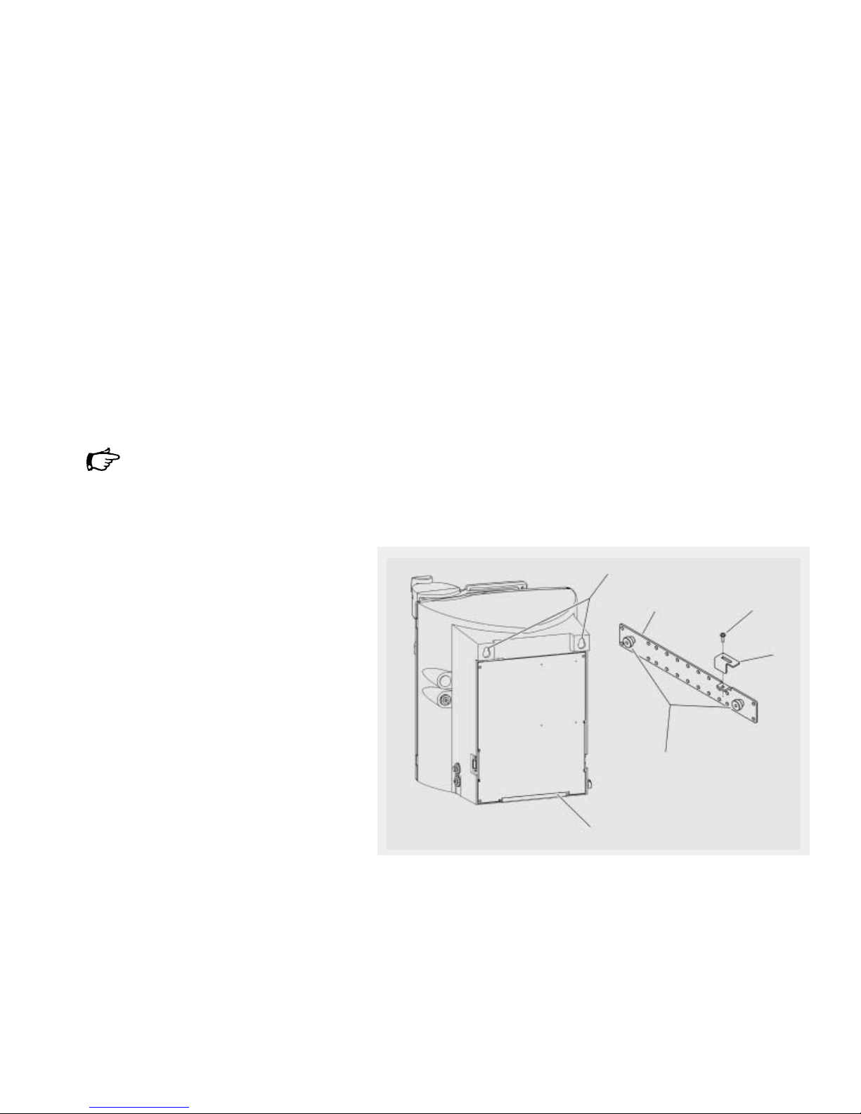
Wall Mounting
Caution!
Wall composition, condition and
construction, as well as fastener
type must be considered when
mounting this unit. The mounting
surface and fasteners selected
must be capable of supporting
a minimum of 25 kg. Inadequate
support and | or fasteners may
result in injury to the operator
and|or damage to the equipment.
A wall bracket (2) is included in the
shipment to enable you to attach
the system securely to the wall so
that it occupies a minimum amount
of space. A clear wall area of
63 + 63 cm is required to mount
the arium system. Two sturdy
keyhole drill holes (1) are located at
the top of the back of the housing
enabling you to hang the unit on
the two pins (5) on the wall bracket.
Use the predrilled holes in the
bracket to fasten the bracket to
the wall. The lower metal profile (6)
on the arium housing functions as
a spacer.
• Ensure that water, a 100 - 240 V
electric socket and an atmospherically vented drain are accessible.
• Fasten the bracket to the wall with
suitable screws and dowels.
• Lower the keyhole drill holes of the
arium 611VF onto the two pins on
the wall bracket.
• Tighten the screw (3) of the metal
support (4) on the right side of
the bracket with a screwdriver until
the metal support rests against the
arium housing.
!
!
!
1
2
3
4
5
6
Lower the arium housing onto the wall-mounting bracket
Page 12

12
Water Inlet Connection
Feed water is supplied to the
system through this inlet (1).
The arium system is supplied with
two water supply adapters – one
with 1” British thread and one
with 4”-NPT.
Caution!
Do not draw water from the top
of an open container or carboy to
supply water to the 611 system.
Damage to the system may result.
Note
We recommend that a customer
supplied shutoff valve be installed
in your feed water line.
If a gravity tank is used to supply
feed water to the 611 system, the
feed water tube must be connected
to the bottom of the tank with a
ridged or hard plumbed connection.
The connection at the bottom
of the gravity must be level with,
or preferably, slightly above the
inlet water connection of the 611
system.
• Connect the free end of the tube
to the appropriate water supply
adapter. Push the tube all the way
into the adapter to seat it properly
(approx. 20 mm).
• Install the tubing adapter onto your
feed water source.
• Cartridges must be installed prior
to supplying feed water to the
system. See cartridge installation
instructions.
• Insert the other end with a quick
disconnect insert into the system’s
counter coupling (1) until it audibly
clicks into place.
Reject Water Connection
The reject water is discarded
through this connection (2).
The reject water tubing has a
4-inch O.D.
Push the tube all the way (approx.
20 mm) into the reject water
connector (2)) to seat it properly.
Direct the other end of the reject
tubing to an atmospheric drain.
Note
Ensure there are no kinks in the
tubing and that it proceeds in
a downward plane.
!!
Connector for feed water tubing
Connector for reject water tubing
1
2
Page 13

Cartridge Installation
• Open both doors of the system.
• Remove both cartridge packs from
their packaging.
One cartridge pack has a label with
a blue dot and the number 1, the
other cartridge has a red dot and
the number 2. In the housing to
the lower left side you will find a
blue labeled cartridge adaptor, on
the lower right side a red cartridge
adaptor.
• Remove the red plugs from the
top of the cartridge pack and push
the blue adapter onto the cartridge
pack with the blue dot. Press
vigorously. Be sure the label with
the blue dot faces you. The adapter
displays “front”.
Two screws each are seated in
the cartridge cover. The two screw
heads must rise from the drillings
of the safe guard slides with the
upper ring of the spacers.
• Push both safe guard slides all
the way under the upper ring
of the spacers, as shown in the
figure opposite.
• Place the cartridge pack with the
blue dot left into the housing and
push until properly seated. Be sure
the label faces you.
• Proceed with the cartridge pack
with the red dot in the same
manner on the right side of the
unit and connect the red coupler.
• Close both doors.
Note
– Moisten the O-rings of the
cartridge pack adapter with
water to facilitate connection.
– Before initial operation the
cartridge packs have to be flushed,
see Cartridge Flush section.
– Screw the final filter onto the NPT
fitting of the dispensing valve only
after flush cycle and sanitization
of cartridge packs and ultrafilter.
13
Initial Operation
Press the adapter onto the cartridge (e.g. red cartridge pack)
Secure the adapter by pushing the two safe guard slides forward over the security
screws
Page 14

14
System Settings
Prior to initial operation of the
arium 611VF, set date and time,
the language for the display text
and the desired measurement units.
To set these functions:
Setting the Date and Time
• The main power switch on the left
hand side of the housing must be
on (“I”).
The arium 611VF will then perform
the system check. The display will
show the following information:
The display will show the following
when the system check is complete
• Press Menu to get in to the Main
Menu
• Select “Setup”. Press ENTER to
confirm.
• Select “Time & Date”. Press ENTER
to confirm.
Display will show the following:
TIME/DATE Standard
U.S.
SETUP Time & Date
Set Point
Meas. Units
MENU Utilities
Maintenance
Setup
MENUOMain Menu
OPEROOperation
ENTRONew Cart. Flush
Sartorius System VF
S/N XXXXXXXX
System Check OK
V1.XX
– When “Standard” is selected,
the date will be displayed in the
DD.MM.YY format and time in
the 24-hour format.
– When “U.S.” is selected, the date
will be displayed in the MM.DD.YY
format and the time in the 12-hour
format.
• Choose a format and press ENTER
to confirm.
• Select Time & Date and use the
arrow keys Y or y to change
current Time & Date settings.
Press ENTER after each digit is set
to move to the next digit.
• Press ENTER to confirm the
Time & Date setting.
The system will then switch to the
previous Operation Mode.
Measurement Units
This feature allows the user to
select how measurement units
are displayed. The user can choose
between MO+cm, µS/cm, with
the option to display readings
compensated to 25°C or uncompensated, or temperature. To set
the measurement units:
• Press MENU to get into the Main
Menu:
• Select “Setup”. Press ENTER to
confirm.
• Select “Measurement Units”.
Press ENTER to confirm.
The display will show the following:
Use the arrow keys Y or y to
select the desired option and press
ENTER to confirm.
Note
In some menus not all menu
items are visible on the display.
Repeatedly press the arrow
key y to display menu items
listed further below.
The system will then switch to the
previous Operation Mode.
MEAS. MO * cm comp.
µS/cm comp.
M
O * cm uncomp.
SETUP Time & Date
Set Point
Meas. Units
MENU Utilities
Maintenance
Setup
Page 15

15
Language
This feature allows the user to
select one of six languages for
the display texts for convenient
operation. The options are German,
English, French, Spanish, Italian
and Japanese. To select a language:
• Press MENU to get into the Main
Menu:
• Select “Setup” and press ENTER to
confirm.
• Use the arrow key y to scroll
down, select “Language” and press
ENTER to confirm.
The display will show the following:
• Use the arrow keys Y or y to
select “Language” and press ENTER
to confirm.
The system will return to the
previous Operation Mode.
LANG. English
French
German
SETUP Time & Date
Set Point
Meas. Units
MENU Utilities
Maintenance
Setup
Set Point
The option “Set Point” allows the
user to select a defined quality level
for the product water in MO+cm
or µS/cm. When the water quality
falls below this Set Point, cartridge
packs should be replaced. The
factory setting for the Set Point
is 10.5 MO+cm. To select the
Set point:
• Press MENU to get into the Main
Menu:
• Select “Setup” and press ENTER to
confirm.
• Select “Set Point” and press ENTER
to confirm.
The display will show the following:
• Select current Set Point or use the
arrow keys Y or y to change to
the desired Set Point. Press ENTER
after each digit is set to move to
the next digit.
• Press ENTER to confirm the Set
Point.
The system will switch to the
previous Operation Mode.
When the water quality drops below
the defined Set Point, in the Normal
Operation Mode the following
display is shown blinking with the
current measurement unit:
Check Set Point
14:32 20.03.01
Set Point
10.5 M
O * cm
SETUP Time & Date
Set Point
Meas. Units
MENUOMain Menu
OPEROOperation
ENTRONew Cart. Flush
Page 16

16
Initial Flush and Sanitization
Prior to initial operation, cartridge
packs and the ultrafilter must be
flushed to remove air and rinse
wetted parts.
Flushing and Purging Air from
the Cartridge Packs
Note
The final filter must not be fitted
onto the dispenser fittings at this
time.
Proceed as follows:
• Press MENU to get into the Main
Menu:
• Select “Maintenance” and press
ENTER to confirm.
• Select “New Cartr. Flush” and press
ENTER to confirm.
The display will show the following:
• Press ENTER.
The New Cartridge Flush will begin
and the display will indicate the
remaining flush time:
When this time has elapsed the
following display is shown with
the word “Finished” blinking:
• Open the dispensing valve and
discard water for approx. 3 minutes.
The New Cartridge Flush is
complete, and the final filter can
now be installed. Refer to filter
installation instructions on page 17.
AIRPURGE/FLUSH CYCLE
Finished
Push OPERO Operation
AIRPURGE/FLUSH CYCLE
19 min
AIRPURGE/FLUSH CYCLE
Press ENTER to Start
MAINTENANCE
UV Life Timer
Sanitization
MENU Utilities
Maintenance
Setup
System Sanitization
To sanitize the system:
• Press MENU to get into the Main
Menu:
• Select “Maintenance” and press
ENTER to confirm.
• Select “Sanitization” and press
ENTER to confirm.
• Follow the instructions on the next
few screens and press ENTER after
each is complete.
Note
Make sure system is depressurized
before attempting to inject
sanitization liquid.
Inject the sanitization liquid with
the syringe as follows (see the
figure below):
Inject the sanitization liquid at the
red adapter fitting
Open Product Outlet
Collect Outlet Water
Inject Sanit. Liquid
Push ENTER
Disconnect Feed Line
Remove End Filter
Push ENTER
MAINTENANCE
UV Life Timer
Sanitization
MENU Utilities
Maintenance
Setup
• Unscrew the luer cap from the
connection of the red cartridge
adapter.
• Inject the sanitization liquid
through the connection into the
system and then slowly remove the
syringe. Some solution may exit.
• Reattach luer end cap.
After pressing ENTER the pump
will run for some seconds. When
the pump stops, the display will
show the following:
After pressing ENTER, the
30-minute active sanitization time
will begin. Time will start to count
down on the display. When the
30 minutes expires, the system will
flush for 6 minutes automatically.
When the time expires, the Sanitization Purity Circulation will begin
automatically and time will count
(60 minutes). The system will enter
Standby Mode automatically when
time expires.
• To complete the Sanitization
Procedure, press the OPERATE|
STOP button and flush 0.5 liters
of water to drain through the
dispensing valve.
The final filter can now be installed.
Close Product Outlet
Reconnect Feed Line
Push ENTER
Page 17

17
Ultrafilter Flush
Prior to initial operation, the
Ultrafilter module has to be flushed.
The system offers a short (1 min)
and a long UF flush (5 min).
Proceed as follows:
• Press MENU to get into the Main
Menu:
• Select “Maintenance” and press
ENTER to confirm.
• Select “UF Flush” and press ENTER
to confirm.
Two flush options are shown.
The Short Flush runs 1 minute,
the Long Flush runs 5 minutes.
• Select “Long” and press ENTER
to confirm.
Display will show the type of flush
selected:
• The flush cycle begins – on the
display, time will begin to count
down. When the time has elapsed,
the system will return to its previous Operation Mode. If necessary
press OPERATE | STOP to get into
the Operation Mode.
• Then open the dispensing valve
and flush 5 liters of water to drain.
• Close the dispensing valve.
LONG FLUSH
5 min
Push ENTER to Start
UF-FLUSH
Short
Long
MAINTENANCE
UV Life Timer
Sanitization
MENU Utilities
Maintenance
Setup
Reset UV Timer Prior to Initial
Operation
Prior to initial operation the
UV Timer must be reset. See the
Activate the UV Bulb Timer section
on page 28.
Final Filter Installation
• Unpack a new final filter.
• Make sure the dispensing valve
is closed.
• Apply two to three wraps of Teflon
tape to threaded NPT fitting of
filter.
• Screw filter clockwise into valve
NPT fitting until snug.
• Remove the protective cap from the
bell assembly and flush 6 liters of
water to drain through final filter.
After this step, the system is now
ready for operation.
Note
Flush an additional 50 ml water
to drain prior to collecting water
for analysis.
Page 18

18
Further Options
Print Data
If you have connected an appropriate printer to the printer port (1) on
your arium system, you have two
print options:
– Print Interval Option
With the Print Interval Option, the
system can be set up to print data
at regular intervals when in Normal
Operation.
– Print Screen Option
The Print Screen Option will only
print the last data recorded.
Note
The arium system has a 9-pin
connection for a serial printer. The
printer must use a separate power
supply and be configured as follows: 19,200 baud, 8-bit, no parity.
To select a print option:
• Press MENU to get into the Main
Menu:
• Select “Utilities” and press ENTER
to confirm.
• Select “Print” and press ENTER
to confirm.
• Select the desired option and press
ENTER to confirm.
– With the Print Interval Option, the
system can be set up to print data
at regular intervals. If you have
selected “Print Interval”, you can
use the control keys for the cursor
to set the desired length of interval
in minutes when prompted by the
display.
– “Print Screen”
The Print Screen Option will only
print the last data recorded. You can
generate a printout of the screen
by pressing ENTER once. After
printing, the system returns to the
previously activated Operate Mode.
PRINT
Print Interval
Print Screen
UTILITIES
Print
Timer Contr.
MENU Utilities
Maintenance
Setup
Pump Protection
If you are using a separate tank
for the feed water supply, you can
connect the water tank and the
arium unit via port (2) with a pump
protection for tank feed systems.
When the tank is empty, the pump
is turned off and water will not
recirculate (only with arium tank).
Printer Port (1) and pump
interlock (2)
2
1
Page 19

Time|Volume Dispense
Note
The arium 611 System must be
equipped with a Time | Volume
Dispense port to function. The
Time|Volume Dispense port is
located on the right side of the
system (1).
Warning!
Be sure a 4” outlet tube is
connected to the Time | Volume
Dispense port located on the right
side of the system. When time
dispense is activated, water will
exit the system via this port. The
end of the outlet tube should be
placed in a filling device.
Note
In order to use the Time | Volume
Dispense feature, you must first
measure the flow rate of the water
from the timed dispense outlet.
Install the supplied 4” tube to the
dispense outlet port. Follow the
menu instructions below to operate
the timed dispense control. When
asked to enter a time, use the up|
down arrows and enter a 1-minute.
Place the open end of the tubing
in a graduated container of at least
2-liter volume. Activate the timer
and allow water to collect in the
container. When the 1-minute
timed dispense has stopped,
measure the volume of water collected. Use the volume collected
in 1-minute (flow rate) to calculate
your dispense time requirement.
For example, you have measured
a 1-liter volume in 1-minute.
Your measured flow rate is 1l/min.
If you need 10 liters to fill a
container, 10 l/1l per minute =
10 minutes dispense time.
Note
If you are using a filter with the
Timed Dispense feature, attach
the filter and rinse the filter for
5 minutes to drain before measuring the flow rate. Measure the flow
rate each time you change filters
or cartridges.
• Press MENU.
• Use Y or y to select “Utilities”.
Press ENTER to confirm.
• Use Y or y to select “Timer
Contr.”. Press ENTER to confirm.
• Use Y or y to change the time.
Press ENTER after each digit is set
to move to the next digit. When the
time has been entered the following
screen is displayed.
• Be sure an outlet tube is connected
to the time dispense port on the
right side of the system. To begin
time dispense press ENTER.
TIMER CONTROL
To Start Filling
Push ENTER
TIMER CONTROL
10.0 min
UTILITIES
Print
Timer Contr.
MENU Utilities
Maintenance
Setup
• The system will begin to dispense
water through the time dispense
port. Time will count down as
shown on the screen below.
• When time expires, the time
dispense port will close and water
will continue to recirculate through
the system. Filling is now finished.
The screen below will show on the
display.
Filling Finished
18.2 MO * c m c
11.25 10.01.02
10 min
18.2 MO * c m c
11.15 10.01.02
19
!
1
Page 20

Set Cell Constant
The resistivity and temperature cell
constants are factory set! If you
have to replace the cell, you will
find the resistivity and temperature
cell constants listed on the cell
cable (1) located inside the arium
system. To provide a more accurate
reading, the cell constants should
be entered in the system memory
by the user. Follow the steps below
to enter the cell constants:
• Power off the arium system (“O”)
and disconnect it from the AC
power outlet.
• Open the front doors and place
the red cartridge pack on the side.
• Locate the white label on the
gray cell cable (1) underneath the
resistivity cell. Record the resistivity
and temperature cell constants.
• Place the red cartridge back in the
system, close the doors, connect the
system to the AC outlet and power
on the arium water system (“I”).
• Press MENU to get into the Main
Menu:
• Use Y or y to select “Utilities”.
Press ENTER to confirm.
• Use Y or y to select “Set Cell
Constant”. Press ENTER to confirm.
• Use Y or y to enter the resis-
tivity (Res) and temperature (Temp)
cell constants previously recorded.
Press ENTER after each digit is set
to move to the next digit.
When the last digit is entered and
you have pressed ENTER to confirm,
the values will be recorded in the
system memory and the system will
enter Operate Mode last activated.
Note
If a digit is entered in error, press
the MENU button to return to the
Main Menu and begin the process
again.
Cell Constants
Res 0.1000
Temp +1.0000
UTILITIES
Print
Timer Contr.
MENU Utilities
Maintenance
Setup
20
Cell constants listed on the cell cable (1)
1
Page 21

Calibration of the System
The system can be calibrated using
an optional N.I.S.T. calibration
module available from Sartorius.
Proceed as follows:
• Turn the power switch on the arium
System to off (“O”) and disconnect
power cord from the unit.
• Disconnect the inlet water line from
the arium system. Open outlet valve
to depressurize the system.
• Open the front doors and move the
red cartridge pack #2 to the side by
rotating the pack to the right.
• Pull up the yellow sealing hood
from the gray resistivity cell cable.
• Disconnect the cell from the
gray cable. Attach the calibration
module where the cell cable was
connected.
• Close the front doors, reattach
the power cord and turn the power
switch on (“I”) – wait for the unit
to complete the system check.
Caution!
Danger of water spillage.
• Press MENU to get into the Main
Menu.
• Use the cursor to select “Maintenance”. Press ENTER to confirm.
• Use the DOWN arrow y to
select “Calibration”. Press ENTER
to confirm.
• After pressing ENTER, the
calibration will begin.
See Owners Manual
for Details.
Push ENTER to Start
MAINTENANCE
UV Life Timer
Sanitization
MENU Utilities
Maintenance
Setup
21
This will take a few minutes
to complete:
When calibration is successful, the
display will show the following:
• Turn the power switch on the arium
System to off (“O”) and remove the
power cord.
• Open the front doors and unplug
the calibration module from the
cell.
• Reattach the gray cable to the cell.
• The yellow sealing hood should
form a tight seal around the
connection.
• Close the doors and reattach the
power cord.
• Connect the inlet water line and
power on the system (“I”).
The calibration is now complete.
The unit is ready for normal
operation.
Calibration
Finished
Calibration
In Process
!
Page 22

Note
If your laboratory uses several liters
of water or more per hour, it is recommended that the system be left
in the Operate Mode to maintain
the highest quality water. During
times of low water consumption
it is recommended that the system
be put in the Standby Mode to
conserve energy. To dispense
water from the standby mode,
press the operate button and allow
the system to circulate for several
minutes prior to drawing water.
After drawing water the system
may be put back in the Standby
Mode. The system should be put
in the Standby Mode overnight
and for weekends and other off
duty hours.
Normal Operation Mode
Once the new cartridge flush
procedure and the sanitization
procedure are completed, you can
start Normal Operation with your
arium 611VF. Turn on the power
switch (“I”), connect the feed water
source. When the internal system
check is complete, the display will
show the following options:
• At this point the system Main
Menu can be accessed and Normal
Operation started by pressing the
OPERATE|STOP button.
MENUOMain Menu
OPEROOperation
ENTRONew Cart. Flush
Dispensing Product Water
In Normal Operation Mode the
display will show the quality of
the treated water according to the
preselected measurement units:
When the required quality of the
product water is displayed, you can
dispense the water at the outlet by
operating the draw-off lever:
• Place a water container under the
outlet.
• Wait until the display shows
the desired resistivity reading
of the water.
• Remove the protective cap on the
bell assembly of the final filter and
• Push the draw-off lever to the right
to dispense the product water.
• After dispensing the water, pull
the draw-off lever forward to close
the valve.
• Place the protective cap back on
the bell assembly.
Note
For all low detection level work,
i.e. with a low content of TOC or
endotoxins, flush an additional
50 to 100 ml water to drain prior
to collecting water for analysis.
(This corresponds to the volume
of the supply to the final filter
and the final filter capsule).
18.2 MO * c m c
14.32 20.02.01
Standby Mode
The “Standby Mode” is designed to
conserve energy while maintaining
water purity during periods of little
or no purified water demand. At
the end of the working day or
before the weekend press the
Standby button to engage the
“Standby Mode”.
The display shows “Standby” when
in Standby Mode.
When the system is in the Standby
Mode, water will recirculate for
15 minutes per hour with the UV
lamp on. The next morning or
working day set the unit back into
service by pressing the Operate|
Stop button.
While in the “Standby Mode” an
“Automatic UF-Flush Cycle” will
occur once in every 24 hours.
During the “Automatic UF-Flush
Cycle”, UF concentrate water is rapidly flushed to drain for 30 seconds.
The first Automatic UF Flush Cycle
will occur approximately 3 hours
after the system is placed in the
“Standby Mode”.
The display shows “Standby Auto
UF-Flush Cycle” during the UF
flush cycle.
Note
To conserve energy, the Standby
Mode is recommended during
non-working hours or when water
consumption is less than 2 liters
per hour. If water consumption
is greater than 2 liters per hour,
the system should be placed in the
Normal Operation Mode.
Standby
Auto UF-Flush Cycle
Standby
22
Start Up|Operation
Page 23

23
System Inactive Mode
If the Operate|Stop button is
pressed while the system is on Normal Operation the arium 611VF is
deactivated. This mode is intended
purely for troubleshooting and
should not be used for prolonged
periods of time. Otherwise the
entire system will have to be
flushed and sanitized or cartridge
packs replaced.
When the system is inactive, the
display shows:
If you need to shut down arium
611VF for an extended period of
time, you should completely drain
it, and remove all cartridge packs
and the ultrafilter to prevent the
growth of bacteria. If the system
has remained inactive and full
of water for more than 96 hours,
you must drain the unit, install
new cartridges and sanitize the
unit prior to use.
System Inactive
Open product outlet valve
Push the draw-off lever forwards to close the product outlet valve.
Page 24

Warning!
Severe electrical shock hazard or
danger of electrocution!
– Only qualified personnel may
service and repair arium 611VF.
– Disconnect arium 611VF from
power supply outlet before
maintenance and servicing.
– Avoid splashing disinfecting
solutions on clothing or skin.
– Ensure all tubing connections are
tight to avoid chemical leakage.
– Turn off feed water and depres-
surize the unit by pushing the
draw-off lever to the right. Only
then should the housing doors
be opened.
– Allow the UV bulb to cool off
before removing it. Be sure to
wear protective gloves to remove
the lamp to avoid leaving finger
prints on bulb or sleeve.
– Carefully follow manufacturer’s
safety instructions on labels of
chemical containers and material
safety data sheets.
Sanitization
Sanitization is necessary to control
bacteria growth and minimize or
prevent the build-up of a bio-film
within the cartridges or piping.
Without Sanitization, the TOC
level in the water can increase
significantly.
The frequency with which you will
need to clean your unit and replace
the cartridges packs depends on
your feed water’s characteristics,
your purity requirements and your
usage. Sanitize your arium 611VF
and replace the cartridges when
the product water purity drops
below acceptable purity levels.
To sanitize the arium 611VF:
• Press MENU to get into the Main
Menu:
• Select “Maintenance” and press
ENTER to confirm.
• Select “Sanitization” and press
ENTER to confirm.
• Follow the instructions on the next
few screens and press ENTER after
each is complete.
Open Product Outlet
Collect Outlet Water
Inject Sanit. Liquid
Push ENTER
Disconnect Feed Line
Remove End Filter
Push ENTER
MAINTENANCE
UV Life Timer
Sanitization
MENU Utilities
Maintenance
Setup
The Sanitization Liquid is injected
using the syringe into the connector ports of the adapter on the red
cartridge adapter (see figure on
page 16):
• Unscrew luer end cap from the
injection port of the red adapter
• Inject the sanitization liquid
through the port and then slowly
remove the syringe.
• Screw luer end cap back on and
close doors.
The 30-minute active sanitization
time will begin. Time will start to
count down on the display. When
the 30 minutes expires, the system
will flush for 6 minutes automatically. When the time expires, the
Sanitization Purity Circulation will
begin automatically and time will
count (60 minutes). The system will
enter Standby Mode automatically
when time expires.
• To complete the Sanitization
Procedure, press the OPERATE|
STOP button and flush 0.5 liters
of water to drain through the
dispensing valve.
• Close the dispensing value and
install a new final filter on the
dispensing valve.
Close Product Outlet
Reconnect Feed Line
Push ENTER
24
Maintenance and Servicing
!
Page 25

Cartridge Replacement
Cartridge pack life is directly related
to feed water quality and water
consumption. Cartridge packs need
to be replaced when product water
quality drops below the requirements established by the user.
To replace the cartridges:
• Turn unit off using the operate|
stop button and the main power
switch on the rear panel (“O”) and
remove the power plug.
• Make sure the inlet water is disconnected from the feed water supply
or from the arium unit disconnect
valve.
• Push the draw-off lever to the right
to release the system pressure.
• When water flow stops, pull drawoff lever forwards again and open
the front doors of the housing.
• Pull the safe guard slides on the
blue adapter towards you.
• Lift the adapter up out of the
cartridge pack.
• Remove the cartridge pack.
• Place a 500-ml container under
the adapter; lower the adapter
until water flow stops.
• Repeat these steps with the second
cartridge adapter.
• Unpack the new cartridge packs.
One cartridge pack is marked with
a blue label, the other with a red
label, (#2). In the housing to the
lower left side you will find a
blue-labeled connector, on the
right a red connector.
• To facilitate connection of the
adapter, moisten O-rings on the
adapter for the cartridge pack.
• Place the blue adapter on to the
blue-labeled cartridge pack (#1)
and push firmly into place (see
figure on page 13).
25
Two screws are seated in the cover
of each cartridge pack. The two
screw heads must rise from the
drillings of the safe guard slides
with the upper ring of the spacers.
• Push both safe guard slides all the
way under the upper ring of the
spacers (see figure on page 13).
• Place the blue-labeled cartridge
pack in the housing on the left,
push all the way home. The label
must be facing you.
• Connect the red adapter to the
red-labeled cartridge pack (#2)
in the same manner on the right
side of the unit.
• Close both doors.
• Open the feed water line or connect
the line to the arium unit.
• Connect arium power cable and
switch on the main switch on the
left side of the housing (“I”).
The new cartridge packs have
to be flushed prior to initial use
(see Flushing the Cartridge Packs
section on page 16).
Note
Do not attach the final filter to the
NPT fitting of the dispensing valve
until after the new cartridge flush
has been completed.
Page 26

Ultrafilter Replacement
The length of your ultrafilter’s
life will depend to some extent
on conditions and use in your lab.
When you are unable to completely
sanitize your system (i.e. you can
no longer obtain pyrogen-free
water even after sanitizing your
system), replace the ultrafilter
cartridge as follows:
• Turn off arium 611VF and disconnect it from the AC power outlet.
• Disconnect the water inlet tube
from the arium System.
• Push the draw-off lever to the
right to release the pressure form
the system.
• When water stops draining, push
the draw-off lever back to the
front. Open the front doors of
the system.
• Remove the two cartridge packs.
Refer to the Section Cartridge
Replacement on page 25) or push
to one side.
• Unscrew the three screw fittings
from the old ultrafilter (see figure
on page 10) and remove the
ultrafilter from the holder.
To do so, hold your index finger
under the lower fitting of the
ultrafilter to keep any water left
in the filter from running out.
Empty the ultrafilter to drain.
• Unpack the new ultrafilter module.
• Connect the tubes that were
unscrewed earlier to the new ultrafilter module:
(1): Inlet is green - bottom
(2): Product water adapter is blueUpper left
(3): Reject adapters are red -Top
Caution!
Danger of leaks.
Make sure that the O-ring on the
blue adapter is seated in a vertical
position before connecting the
ultrafilter.
• Push the ultrafilter module back
into the holder so that it engages.
The connection fitting on the side
should be on the upper left.
• Re-install the two cartridge packs
or push them back in place (see
Cartridge Replacement, page 25).
• Close the two doors.
• Open the inlet water or reconnect
the arium System to the feed water
supply.
• Connect arium power cable and
switch on the main switch on the
left side of the housing (“I”).
• Perform a “long” UF Flush
(5 minutes) (for details see
UF Flush Section on page 17).
Note
1 or 2 additional short flush cycles
may be required to remove air from
the UF module.
Replacing the Final Filter
Replace the final filter whenever
the following conditions occur:
– Every 30 days
– The product water flow rate is
reduced, or
– Bacteria break through is detected.
The final filter is shipped assembled
with a bell. To replace the final
filter assembly:
• Remove the old final filter assembly
by turning it counterclockwise.
• Remove the new final filter assem-
bly from its bag.
• Apply two to three wraps of Teflon
tape to the threaded end of the
filter.
• Screw the filter clockwise into the
outlet until snug.
• Rinse approx. 6 liters of water
through the filter to drain prior
to using the product water.
Note
If a newly installed final filter clogs
rapidly after installation, arium
611VF may need to be sanitized
to remove bacterial contaminants.
26
!!
Page 27

Cell Cleaning
Warning!
Severe electrical shock hazard
or danger of electrocution!
– Only qualified personnel may
service and repair arium 611VF.
– Disconnect arium 611VF from
the AC power outlet before
maintenance and servicing.
– Depressurize the unit by turning
off feed water and pushing the
draw-off lever to the right before
opening the front doors to replace
the cartridges.
Caution!
Malfunction of the resistivity cell!
– The cell electrodes (4) are etched
to improve wetting characteristics.
Do not mechanically abrade or
damage the surface (i.e. do not
clean with a wire brush, sandpaper,
etc.).
– Do not immerse the entire cell
assembly in cleaning solution,
only the electrode portion.
• Turn off arium 611VF (“O”) and
disconnect it from the AC power
outlet.
• Disconnect the feed water supply
or the line to the arium unit.
• Push the draw-off lever to the right
in order to depressurize the system.
• When water flow stops, pull the
draw-off lever back forwards and
open the front doors.
• Remove the red-labeled cartridge
pack from the housing.
• Remove the gray cell cable (2)
under the yellow hood covering.
• Remove the cell (1) from the black
socket and unscrew it.
• Carefully remove the O-ring (3)
before cleaning the cell.
• Clean the cell in a mild detergent
solution using a soft brush or
immerse for 10 min in a 1%
hydrochloric or sulfuric acid
solution.
Warning!
Danger of acid burns!
Carefully follow the acid manufacturer’s warnings and recommended
handling procedures found on pack
labels and material safety data
sheets. Wear protective gloves and
glasses.
27
• Thoroughly rinse the cell in
deionized or distilled water following the detergent or acid cleaning.
• Apply two wraps of Teflon tape
to threaded end of cell.
• Reinstall the cell well and handtighten.
• Reconnect the gray cable.
• Reinstall the right cartridge pack
into the housing.
• Close the front doors.
• Open the feed water line or
reconnect it to the arium system.
• Reconnect the unit to the AC power
outlet and turn the unit back on
using the main power switch on the
left side of the housing (“I”). Press
the Operate | stop button to start
system.
• Open draw off valve and flush
water to drain for 2 minutes.
• Close valve.
• The unit is now ready to
operate again.
Clean the metal portion (4) of the
resistivity cell
2
1
!
!
!!
3
4
Remove the gray cable from the resistivity cell
Page 28

Note
Make sure that the O-Ring on the
new lamp is not dislocated.
• Replace the black plastic cover over
the bulb holder and carefully screw
into stainless steel chamber. After
O-ring begins to seat tighten only a
further 4 turn!
• Reconnect the power plug (1) to
the bulb holder in the black plastic
cap (2).
• Push the recessed shield over
the power cord and screw on
to the stainless steel chamber.
• Put the cartridge pack back into
the unit.
• Close the doors.
• Open the inlet water line or
reconnect it to the arium system.
• Reconnect the AC power cable und
turn the unit back on using the
main power switch on the left side
of the housing (“I”).
• Perform a 5 minute UF flush cycle
to purge air from the system.
Note
After installing a new UV bulb reset
the timer, which reminds you to
replace the UV bulb. Refer to the
following section.
• Press the OPERATE| STOP key to
put the system into OPERATE
Mode.
28
To replace the ultraviolet bulb:
• Turn off arium 611VF using the
main power switch (“O”) and
disconnect it from the AC power
outlet.
• Shut-off or disconnect the feed
water supply.
• Push the draw-off lever back in
order to depressurize the system.
• When water stops draining from
the system, pull the draw-off lever
back towards you and open the
front doors.
• Take the left cartridge pack with
connected adapter out of the
housing or slide it to the right
towards the center.
• Remove the screw from the metal
shield or plastic cap.
• Remove the power plug (1) from
the black plastic cap (2).
• Unscrew the top plastic cover from
the stainless steel chamber of the
UV bulb (see top figure on the next
page).
• Hold a beaker (300 ... 500 ml size)
under the black plastic cap (2) and
slowly unscrew the cap from the
stainless steel chamber (by turning
it counterclockwise); collect any
draining water in the beaker.
If the plastic cap is seated too
tightly (2), insert a screwdriver
into both grooves and carefully
lift up the cap.
• Then remove the old lamp (4) from
the stainless steel chamber.
• Insert new lamp with new O-Ring
(3) into the stainless steel chamber.
UV Bulb Replacement
The UV bulb consists of a quartz
glass tube with integrated mercury
bulb. The quartz glass tube and
the mercury bulb glass deteriorate
during exposure to UV radiation
and will eventually absorb the most
desirable wavelengths. If only the
mercury bulb is replaced, there is
no guarantee that the desired UV
radiation will pass the quartz sleeve
in the reaction chamber.
Warning!
Danger of personal injury!
– Depressurize the system prior
to opening front doors.
– Allow a defective UV bulb to cool
off before removing it.
Do not leave finger prints on
a new bulb.
– Ultraviolet radiation is harmful to
the eyes and skin. Do not attempt
to observe the lamp directly when
energized.
Caution
Danger of irreversibly damaging
UV bulb!
Do not touch the glass portion
of the lamp. It is recommended
that lint free gloves be worn when
handling the lamp.
The glass portion must be free
of fingerprints, perspiration, etc.
A single fingerprint will reduce
the effectiveness of the lamp.
Clean the lamp with isopropyl
alcohol and a lint free cloth.
!
!!
Page 29

Remove screw from metal shield
Remove UV bulb (4) from stainless steel chamber
29
Activate the UV Timer
The UV bulb should be replaced
approximately every six months.
A timer can be activated to display
a message every 6 months to
remind you that the UV bulb is
ready to be replaced.
To activate the timer after installing
a new UV bulb:
• Press MENU to get into the Main
Menu:
• Select “Maintenance” and press
ENTER to confirm.
• Select “UV Timer” by using y
and press ENTER to confirm.
• Press ENTER to reset the timer.
The internal timer is reset and will
remind you to replace the UV bulb
after 6 months.
• Alternatively press the MENU key
to return to the Main Menu without
resetting the timer.
After 6 months the display will
show the following:
18.2 MO * c m c
Change UV Bulb
09.48 23.04.01
UV LIFE TIMER
Timer Reset
Escape
MAINTENANCE
UV Life Timer
Sanitization
MENU Utilities
Maintenance
Setup
1234 5
Page 30

Fuse Replacement
arium 611VF has two fuses for
the unit.
Warning!
Severe electrical shock hazard
or danger of electrocution!
– Only qualified personnel may
service and repair arium 611VF.
– Disconnect arium 611VF from the
AC power outlet before maintenance and servicing.
– Ensure all tubing connections are
tight to avoid leakage.
– Depressurize the unit by pushing
back the draw-off lever to the right
before opening the front doors to
exchange the cartridges.
• Turn off arium 611VF using
the main power switch (“O”)
and disconnect it from the AC
power outlet.
The fuse drawer with two safety
fuses is located on the left side of
the housing above the main power
switch.
• Gently press the locking device of
the fuse drawer upwards and pull
out the fuse drawer (see figure).
Caution!
Danger of damage to components!
First determine why the fuse blew
and eliminate the cause. Then
replace any defective fuses with
new ones.
• Remove the old fuses and replace
with fuses of the same type and
rating.
• Place fuse drawer back into the
housing until it clicks into place.
• Reconnect the unit to the AC power
outlet and turn the unit back on
using the main power switch (“I”).
The unit is now ready to operate
again.
30
!
!!
Page 31

31
Appendix
Problem Possible Causes Solutions
Pump not operating, control panel not lit No electrical power to arium 611VF. Ensure that the arium 611VF power cord
is connected to a live power source and
completely plugged into electrical outlet.
The power entry plug fuse is defective. Identify and eliminate problem, replace
the fuse (see section on Fuse Replacement
on page 29).
The internal AC adapter fuse is Contact Sartorius Customer Service.
defective.
Pump runs, but no display Connector from main PCB to display Disconnect unit from AC power.
PCB not plugged in. Check and reconnect.
Pump does not run. Display lit. Pump worn out or defective. Replace pump.
System leakage Fitting is not tight or broken. Change or tighten fitting.
High TOC UV bulb is not working. Replace UV bulb (see page 27).
Exhausted cartridge packs Replace the cartridge packs (see page 25).
The system is contaminated. Perform sanitization (see section on System
Sanitization on page 16).
Check feed water quality.
Resistivity too low. Exhausted cartridge packs Replace the cartridge packs (see Cartridge
Pack Replacement section on page 25).
The system is contaminated. Replace the cartridge packs (see section on
Cartridge Pack Replacement on page 25)
and perform sanitization (see section on
System Sanitization on page 16)
Low resistivity. Resistivity cell dirty. Clean cell (see section on Cell Cleaning
on page 30).
The system is not calibrated. Perform calibration (see section on System
Calibration on page 21).
High endotoxin level. The system is contaminated. Replace the cartridge packs (see section on
Cartridge Pack Replacement on page 25),
perform sanitization (see section on System
Sanitization on page 16) and replace
the ultrafilter (see section on Ultrafilter
Replacement on page 26).
The ultrafilter is contaminated Sanitize or replace the ultrafilter
or defective. (see section on Ultrafilter Replacement
on page 26).
Reduced or no product water flow The final filter is clogged. Replace the final filter (see section on
from the final filter. Final filter Replacement on page 26).
The system is contaminated. Replace the cartridge packs (see section on
Cartridge Pack Replacement on page 25)
and perform sanitization (see section on
System Sanitization on page 16).
Pump defective Replace pump.
Short cartridge life. Feed water quality is low. Check the feed water source.
Increased water consumption. Replace cartridge packs with fresh ones.
Display shows “Replace UV bulb”. UV bulb burnt out. Replace UV bulb (see section on UV bulb
Replacement on page 27).
No Display Display cable not connected Connect display cable.
Troubleshooting Guide
Immediately after you discover any
malfunction, use the main power
switch to turn off arium 611VF.
Then use the troubleshooting chart
below to try to find out what the
problem is and take the suggested
action.
Page 32

32
Specifications
Dimensions W + D + H 43.2 + 48.3 + 34.3 [cm]
Empty weight 15.9 kg
Operating weight 23.6 kg
Clearance requirements Sides: 10 cm minimum for cable and tubing connections
Front: 40 cm minimum for opening the doors
Inlet water requirements arium 611VF requires water pretreated by:
- distillation
- deionization or
- reverse osmosis
Distilled water: > 250 KO · cm (< 4 µS/cm)
RO water: TDS < 25 ppm CaCO
3
> 20 KO · cm (< 50 µS/cm)
Deionized water: TDS < 10 ppm CaCO
3
> 50 KO · cm (<20 µS/cm),
All: Turbidity < 1 N.T.U.
Silica < 1000 ppb
TOC < 1000 ppb
Pressure: From atmospheric tank inlet to a maximum inlet pressure of 7 bar
Product water capabilities Quality of the
purified water: 18.2 MO + cm at 25°C
RNase-/DNase-/DNA-free
Bacteria: < 1 CFU/100 ml
TOC: < 1 ppb
Endotoxin: < 0,001 EU/ml
Flow rate Up to 1.5 l/min maximum at minimum inlet feed water pressure of 2.0 bar at 50 HZ and
with a new final filter.
Environmental conditions Operating: 5 °C - 28°C; 80% relative humidity, non-condensing
Storage: 5 °C - 45°C; 80% relative humidity, non condensing
Electrical requirements 100-240 V~, 50/60 Hz, 1 phase
Fuses power entry 2 fuses 5 + 20 mm, time lag, 250 V, 1 A
Installation Category II (over-voltage) in accordance with IEC 664,
Pollution Degree 2 in accordance with IEC 664.
Altitude limit: 5,000 meters.
Complies with the EMV: EN 50081-1, EN 50082-1
following standards Safety: IEC 1010-1-92
Page 33

Accessories and Replacement Parts
Ordering Replacement Parts
When requesting any customer service or replacement parts or in any correspondence about arium 611VF, be sure to state the complete model number and the
serial number that are on the Specification Plate label on the rear panel of the unit.
You can obtain any replacement parts listed in this manual from Sartorius or from
your local Sartorius dealer.
Order No. Description
611VF Complete Unit arium 611VF
611CKRU Consumable kit with
– 611CPR for RO or Distilled inlet water if application
requires low TOC. Will be used on the left (blue) side
of the system.
– 611CPU for low TOC level application in systems with an
UV lamp chamber. Will be used on the right (red) side of
the system.
– 5441307H4—NO Sartopore 2 150 Final Filter (2+).
611CKDU Consumable kit with
– 611CPD for DI water if application requires low TOC levels.
Will be used on the left (blue) side of the system and Pack.
– 611CPU for low TOC level application in systems with an
UV lamp chamber. Will be used on the right (red) side of
the system.
– 5441307H4—NO Sartopore 2 150 Final Filter (2+).
611CDU5 Replacement Ultrafilter Cartridge arium 611
5441307H4—NO—B Sartopore 2 150 Final Filter (Pack of 5)
611CEL1 Replacement UV lamp arium 611
611CEF1 Replacement fuses power inlet 2 fuses
611CDS2 Sanitization Kit 2 syringes
611CDS6 Sanitization Kit 6 syringes
611AMA1 Inlet feed water adapter 4” NPTF 1”
611AEC1 Calibration module
611AMB1 Wall Bracket
33
Page 34

Page 35

Page 36

Printed in Germany on paper that has
been bleached without any use of chlorine
W4A000 · KT
Publication No.: SLG6010-e02042
Order No.: 85030-513-68
Sartorius AG
Weender Landstrasse 94-108
37075 Goettingen, Germany
Telephone +49.551.308.0
Telefax +49.551.308.3289
www.sartorius.com
Copyright by Sartorius AG,
Goettingen, Germany.
All rights reserved. No part
of this publication may be
reprinted or translated in any
form or by any means without
the prior written permission
of Sartorius AG.
The status of the information,
specifications and illustrations in
this manual is indicated by the
date given below. Sartorius AG
reserves the right to make
changes to the technology,
features, specifications, and
design of the equipment
without notice.
Status:
April 2002, Sartorius AG,
Goettingen, Germany
 Loading...