

Page 1
89066-000-50
Betriebsanleitung | Operating Instructions
16692|16695
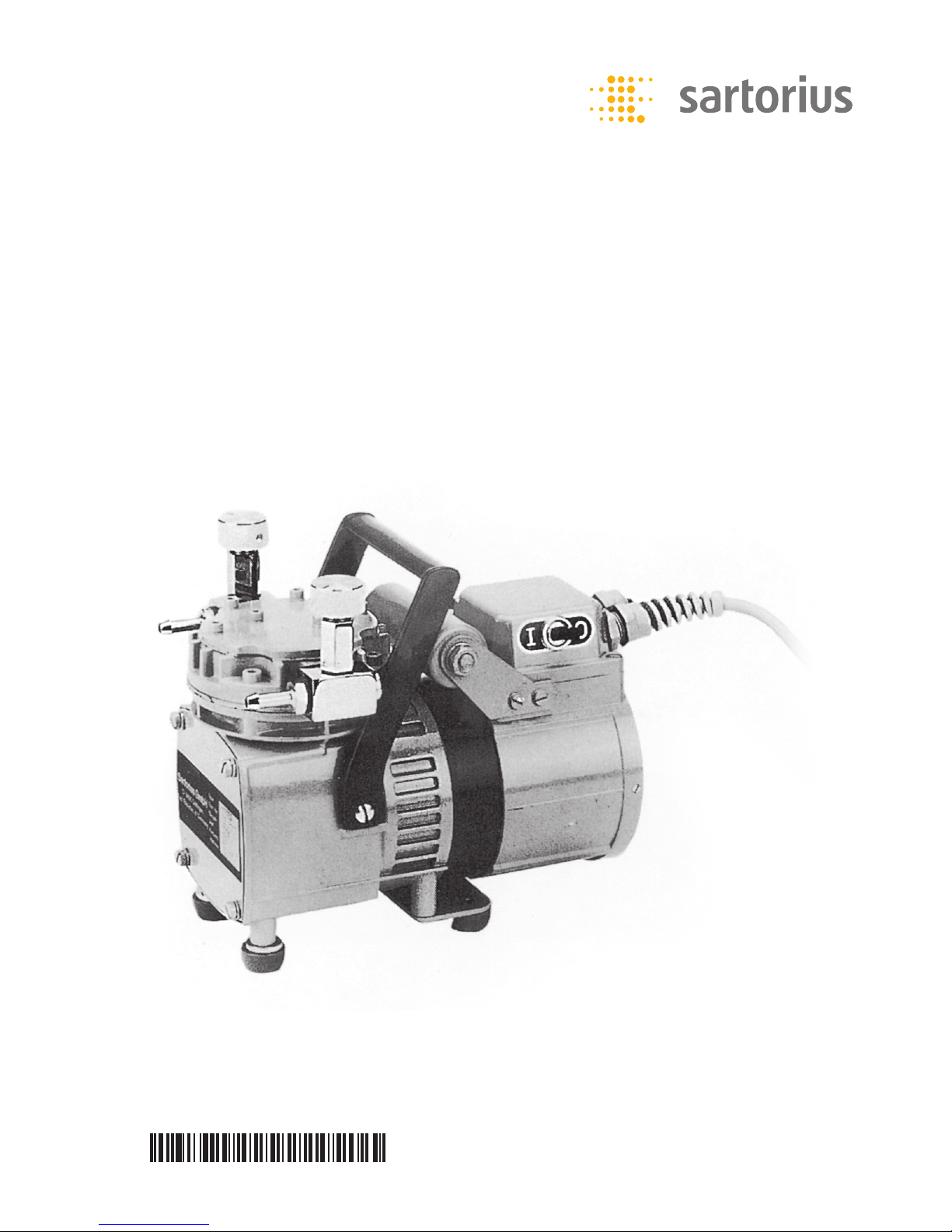
Membran-Vakuumpumpen | Diaphragm Vacuum Pumps
Page 2

2 |
4
3
6 5
1 2
Abb.1 | Fig.1
List of Parts
Bezeichnung in dem Foto
Reduzierventile Nr. 1
Tragegriff Nr. 2
Netzschalter Nr. 3
Lüfterhaube Nr. 4
Gehäuse Nr. 5
Typenschild Nr. 6
Ausgang Nr. 7
Membrankopf Nr. 8
Inbusschrauben (4 Stück) Nr. 9
Eingang Nr. 10
Inbusschrauben (7 Stück) Nr. 11
Deckel Nr. 12
Teilebenennung
Designation Shown in photo as
Reducing valves No. 1
Carrying handle No. 2
Power switch No. 3
End cover plate (for fan) No. 4
Housing No. 5
Manufacturer’s label No. 6
Outlet connector No. 7
Diaphragm head No. 8
Allen screws (4) No. 9
Inlet connector No. 10
Allen screws (7) No. 11
Cover plate No. 12
7
8
9
10
11
12
Page 3

| 3
Contents
Die einköpfige, elektrisch betriebene
Membran-Vakuumpumpe bietet hohe Dauerleistung bei leisem Lauf. Sie ist mit einem
Tragegriff, Gummifüßen, Anschlusskasten mit
Netzkabel und Schlauchstutzen ausgestattet.
Reduzierventile ermöglichen die Regulierung
des Vakuums. Die maximale Förderleistung
beträgt 20 l/min. Das Endvakuum beträgt
100 mbar (76 Torr).
Die Motor-Schutzart IP44 ist ausgeführt nach
VDE 0530, Teil 5.
Die elektrische Ausführung dieses Motors
entspricht VDE 0530, Teil 1.
Inhaltsverzeichnis
The Sartorius Single-Headed Electric
Diaphragm Vacuum Pump is built to last,
runs quietly and provides a high output.
The pump comes equipped with a carrying
handle; rubber feet; built-in power supply
with line cord; and hose connectors.
The reducing valves allow the vacuum to
be regulated. The final vacuum output is
100 mbar (76 torr). The pump’s maximum
pumping rate is 20 I/min.
The internationally recognized protection
rating IP 44* for the pump motor conforms
to the German standard VDE 0530, Section 5.
The electrical design of the pump motor complies with the German standard VDE 0530,
Section 1.
* described in the IEC Publication 144
and entails protection against contact and
splashing
1 Specifications.......................4
2 Important Notes ....................4
3 Maintenance .......................5
3.1 Changing the Diaphragm. .........5
3.2 Changing the Reed Valves .........6
4 Recommended Accessories ...........7
5 Spare Parts .........................7
EC / EU Declaration of Conformity........8
FCC Supplier’s Declaration of Conformity..9
1 Technische Daten....................4
2 Wichtige Hinweise...................4
3 Wartung ...........................5
3.1 Auswechseln der Membrane. .......5
3.2 Auswechseln der Ventilfedern. .....6
4 Empfehlenswertes Zubehör ...........7
5 Ersatzteile ..........................7
EC / EU Declaration of Conformity........8
FCC Supplier’s Declaration of Conformity..9
Page 4

4 |
1 Technische Daten
16692: 220 V, 50 Hz
16695: 110 V, 60 Hz
Membran: Neopren
Max. Förderleistung (bei atm. Druck):
20 l/min
Endvakuum: 100 mbar (76 Torr)
Motorleistung: 60 W
Stromaufnahme: 0,75 Amp.
Max. zulässige Umgebungstemperatur: 40°C
Gewicht: ca. 4,5 kg
Abmessungen (mm): 203 x 145 x 187
Anschluss: Ein- und Ausgang:
Olive für 5 mm Schlauch
2 Wichtige Hinweise 2 Important Notes
1. Der elektrische Anschluss muss mit den
Angaben auf dem Typenschild übereinstimmen.
2. Die Umgebungstemperatur darf nicht
über 40°C ansteigen. Geräte, die kundenseitig eingebaut werden, müssen ausreichend be- und entlüftet sein.
3. Das Gerät darf nicht gegen Last (Vakuum)
anlaufen.
4. Es dürfen nur Luft, Gase und nicht
aggressive Dämpfe gefördert werden,
jedoch keine Flüssigkeiten.
5. Das Gerät muss vor Spritz- und Schwallwasser sowie vor übermäßigem Staub
geschützt sein.
1. Before you plug in the pump, check
the manufacturer’s label to make sure the
voltage rating matches your local line
voltage (mains).
2. The ambient temperature may not exceed
40°C. Pumps installed in equipment by
the customer must have sufficient ventila tion inside and outside the cabinet.
3. Do not start the pump under load
(vacuum).
4. The pump may only be used for air, gases
and non-aggressive vapors, but not liquids.
5. Protect the pump against jets and
gushes of water (hosedown environments)
including excessive dust.
1 Specifications
16692: 220 V, 50 Hz
16695: 110 V, 60 Hz
Diaphragm: neoprene
Max. pumping rate (at atmospheric
pressure): 20 I/min.
Final vacuum: 100 mbar (76 torr)
Motor output: 60 W
Power consumption: 0.75 amp
Max. permissible ambient temperature:
40°C
Weight: approx. 4.5 kg
Dimensions (mm): 203 x 145 x 187
Connections: inlet and outlet:
connector for 5 mm hose
Page 5

| 5
3 Maintenance
Die Membran-Vakuumpumpe bedarf keiner
regelmäßigen Wartung. Die Kugel lager sind
überdimensioniert und die Füllung mit
einem Spezialfett reicht aus für die Gesamtlebensdauer des Gerätes. Membrane und
Ventile sind die einzigen Verschleißteile. Das
Auswechseln dieser Bauelemente erfordert
jedoch keine besonderen technischen Kenntnisse und lässt sich in wenigen Minuten am
Standort der Pumpe durchführen.
3.1 Auswechseln der Membrane (s. Abb.1).
3.1.1 Kennzeichnen Sie die Stellung des
Membrankopfes (8) zum Gehäuse (5) mit
einem Bleistift.
3.1.2 Lösen Sie die 4 Inbusschrauben (9)
und nehmen Sie den Membrankopf ab.
3.1.3 Nun lösen Sie die Senkschraube
und nehmen nacheinander Druckscheibe,
Zahnscheibe und Membrane ab.
3.1.4 Entfernen Sie die Lüfterhaube (4)
des Motors auf der rechten Geräteseite
(2 Schrauben) und drehen Sie den Lüfterflügel, bis das Pleuel in Mittelstellung ist.
Legen Sie dann die neue Membrane ein.
3.1.5 Auf die Membrane legen Sie nun erst die
Druckscheibe mit der flachen Seite nach
unten und dann passend die Zahnscheibe.
Ziehen Sie die Senkschraube gefühlvoll, aber
fest an.
3.1.6 Setzen Sie nun den Membrankopf (8)
wieder in die gekennzeichnete Position und
ziehen Sie die Inbusschrauben (9) über Kreuz
gleichmäßig an.
3.1.7 Kontrollieren Sie den leichten Lauf,
indem Sie den Lüfterflügel einmal ganz
herumdrehen und schrauben Sie die Lüfterhaube (4) wieder an.
3 Wartung
The Sartorius Diaphragm Vacuum Pump
does not require regular maintenance. The
ball bearings are oversized and sufficiently
lubricated with a special grease to last for
the pump’s entire service life. The diaphragms
and valves are the only parts subject to wear.
However, changing these parts does not
require any special technical expertise and
can be easily done on-site within a few
minutes.
3.1 Changing the Diaphragm (see Fig.1).
3.1.1 Use a pencil to mark the position
of the diaphragm head (8) in relation to
the housing (5).
3.1.2 Untighten the 4 Allen screws (9), and
remove the diaphragm head.
3.1.3 Now loosen the countersunk screw,
and remove the retainer plate, star lock
washer and diaphragm one by one.
3.1.4 Remove the end cover plate (4) for
the motor fan from the right side of the
pump (remove the 2 screws) and turn the
disk flywheel until the connecting rod is in
mid-position. Next, install the new diaphragm.
3.1.5 Now replace the retainer plate first
with the flat side facedown on the diaphragm
followed by the star lock washer, making
sure that it is properly aligned. Carefully but
securely tighten the countersunk screw.
3.1.6 Next, replace the diaphragm head (8)
in the marked position and uniformly tighten
the Allen screws (9) in opposite diagonal
pairs.
3.1.7 Check that the pump runs smoothly by
rotating the disk flywheel one complete turn
and then replace the end cover plate (4).
Page 6

6 |
3.2 Auswechseln der Ventilfedern.
I. Untere Ventilfeder
3.2.1 Führen Sie die Demontage des
Membran kopfes wie unter 3.1.1 und 3.1.2
beschrieben durch.
3.2.2 Lösen Sie die Schraube und tauschen Sie
die Ventilfeder aus.
II. Obere Ventilfeder
3.2.3 Lösen Sie die 7 Inbusschrauben (11) und
heben Sie den Deckel (12) und die Dichtung
ab, wenn nötig vorher Farbe am Deckelrand
entfernen (mit dem Schraubenzieher
ab schaben).
3.2.4 Lösen Sie die Schraube und tauschen
Sie die Ventilfeder aus.
3.2.5 Ziehen Sie die Schraube wieder an
und setzen Sie den Deckel mit der neuen
Dichtung ein. Befestigen Sie die 7 Inbusschrauben wieder. Führen Sie die Montage
des Membrankopfes und die Überprüfung
des Laufes wie ab 3.1.6 beschrieben durch.
3.2 Changing the Reed Valves
I. Lower Valve
3.2.1 Remove the diaphragm head as
described in steps 3.1.1 and 3.1.2.
3.2.2 Loosen the screw, and exchange the
spring steel reed valves.
II. Upper Valve
3.2.3 Loosen the 7 Allen screws (11) and
remove the cover plate (12) and gasket. If
necessary, remove the paint from the edge
of the cover beforehand (use a screwdriver
to scrape it off).
3.2.4 Loosen the screw, and exchange the
reed valves.
3.2.5 Retighten the cheese head screw and
replace the cover plate with a new gasket.
Retighten the 7 Allen screws. Remount the
diaphragm head, and check that the pump
runs smoothly as described in 3.1.6 and 3.1.7.
Page 7

| 7
16610 Woulff’sche Flasche, 500 ml
16623 Gummivakuumschlauch (1 m)
16610 Woulff’s bottle, 500 ml
16623 Rubber vacuum hose (1 m)
4 Empfehlenswertes Zubehör 4 Recommended Accessories
5 Ersatzteile 5 Spare Parts
6986105
Ersatzteilkit, bestehend aus:
– 1 Neoprenmembran
– 2 Ventilfedern
– 1 Kopfdichtung
6986105
Spare parts kit consisting of:
– 1 neoprene diaphragm
– 2 reed valves
– 1 gasket for the diaphragm head
Page 8

8 |
EC / EU Declaration of Conformity
Page 9

| 9
FCC Supplier’s Declaration of Conformity
S
upplier’s Declaration of Conformity
___________________________________________________________________________________________
Doc: 2417166-00 SLI18FCC045-00.en 1 / 1 PMF: 2035209 OP-113_fo1_2015.10.12
Device type Pump
M
odel 16615, 16695, 16694-1-60-06, 16694-1-60-22
P
arty issuing Supplier’s Declaration of Conformity /
R
esponsible Party – U.S. Contact Information
Sartorius Corporation
5 Orville Dr Suite 200
11716 Bohemia, NY
USA
Telephone: +1.631.254.4249
F
CC Compliance Statement
This device complies with Part 15 of the FCC Rules. Operation is subject to the following two
conditions: (1) This device may not cause harmful interference, and (2) this device must
accept any interference received, including interference that may cause undesired operation.
I
nformation to the user
Note: This equipment has been tested and found to comply with the limits for a c
lass B
digital device, pursuant to part 15 of the FCC Rules. These limits are designed to provide
reasonable protection against harmful interference in a residential installation. This
equipment generates, uses and can radiate radio frequency energy and if not installed and
used in accordance with the instructions, may cause harmful interference to radio
communications. However, there is no guarantee that interference will not occur in a
particular installation. If this equipment does cause harmful interference to radio or
television reception, which can be determined by turning the equipment off and on, the user
is encouraged to try to correct the interference by one or more of the following measures:
• Reorient or relocate the receiving antenna.
• Increase the separation between the equipment and receiver.
• Connect the equipment into an outlet on a circuit different from that
to which the receiver is connected.
• Consult the dealer or an experienced radio/TV technician for help.
Connections between the device and peripherals must be made using shielded cables in order
to maintain compliance with FCC radio frequency emission limits.
Any modifications made to this device that are not approved by Sartorius may void the
authority granted to the user by the FCC to operate this equipment.
FCC
Page 10

Printed in the EU on paper bleached
without chlorine.
Publication No.: SL-6021-a181007
10 | 2018
Last updated:
The information and figures contained in these
instructions correspond to the version date
specified below.
Sartorius reserves the right to make changes
to the technology, features, specifications and
design of the equipment without notice.
Masculine or feminine forms are used to
facilitate legibility in these instructions and
always simultaneously denote the other
gender as well.
Copyright notice:
This instruction manual, including all of its
components, is protected by copyright.
Any use beyond the limits of the copyright law
is not permitted without our approval.
This applies in particular to reprinting,
translation and editing irrespective of the type
of media used.
© Sartorius Germany
Sartorius Lab Instruments GmbH & Co. KG
Otto-Brenner-Strasse 20
37079 Goettingen, Germany
Phone: +49.551.308.0
www.sartorius.com
 Loading...