

89009-000-50
Betriebsanleitung | Operating Instructions
16612 |16615
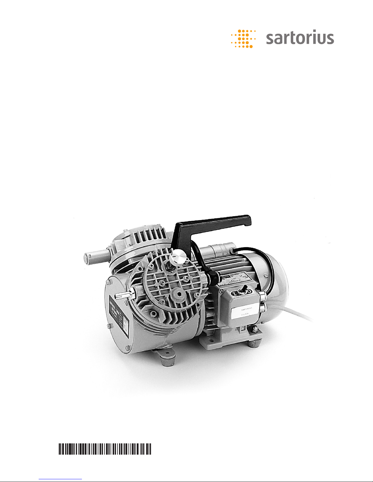
Membran-Vakuumpumpen | Diaphragm Vacuum Pumps

6
7
8
14
13
12
11
10 9
1 2 3 4 5
Abb.1 | Fig.1
2 |
Teilebenennung List of Parts
Bezeichnung in dem Foto
Membranköpfe Nr. 1
Reduzierventil Nr. 2
Verbindungsschlauch Nr. 3
Überwurfmutter Nr. 4
Tragegriff Nr. 5
Lüfterhaube Nr. 6
Typenschild Nr. 7
Netzschalter Nr. 8
Deckel Nr. 9
Inbusschrauben (6 Stück) Nr. 10
Gehäuse Nr. 11
Inbusschrauben (4 Stück) Nr. 12
Vakuumanschluss Nr. 13
Luftausgang Nr. 14
Designation Shown in photo as
Diaphragm heads No. 1
Reducing valve No. 2
Connecting tube No. 3
Threaded nut No. 4
Carrying handle No. 5
End cover plate (for fan) No. 6
Manufacturer’s label No. 7
Power switch No. 8
Cover plate No. 9
Allen screws (6) No. 10
Housing No. 11
Allen screws (4) No. 12
Vacuum connection No. 13
Air exhaust No. 14

Inhaltsverzeichnis Contents
1. Technische Daten
2. Wichtige Hinweise
3. Wartung
3.1 Auswechseln der Membrane
3.2 Auswechseln der Ventilfedern
4. Empfehlenswertes Zubehör
5. Ersatzteile
Die elektrisch betriebene Membran-Vakuumpumpe ist besonders bei der Verwendung
von Mehrfach-Absaugvorrichtungen von
Vorteil und bietet hohe Dauerleistung
bei leisem Lauf. Sie ist mit einem Tragegriff,
Gummifüßen, Anschlusskasten mit Netzkabel (2 m), Geräuschdämpfer, saugseitig
in Reihe verschalteten Köpfen (2-stufig)
und Schlauchstutzen ausgestattet. Das
Reduzierventil ermöglicht die Regulierung
des Vakuums.
Die maximale Förderleistung beträgt 26 l/
min. Das Endvakuum beträgt 13 mbar
(10 Torr). Die Motor-Schutzart IP 44 ist
ausgeführt nach VDE 0530, Teil 5. Die
elektrische Ausführung dieses Motors entspricht VDE 0530, Teil 1.
1. Specifications
2. Important Notes
3. Maintenance
3.1 Changing the Diaphragm
3.2 Changing the Reed Valves
4. Recommended Accessories
5. Spare Parts
The Sartorius Stedim Biotech Electric
Diaphragm Vacuum Pump is especially
convenient for using multibranch vacuum
manifolds. Built to last, it runs quietly while
providing a high performance. The pump
comes equipped with a carrying handle;
rubber feet; built-in power supply with line
cord (2 m); muffler; serially connected twin
pump heads on the suction side; and hose
connector.
The reducing valve allows the vacuum to
be regulated. The final vacuum is 13 mbar
(10 torr). The pump’s maximum suction
rate is 26 l/min. The internationally recognized protection rating IP 44* for the pump
motor (* described in the IEC Publication
144 and entails protection against contact
and splashing) conforms to the German
standard VDE 0530, Section 5. The electrical
design of the pump motor complies with the
German standard VDE 0530, Section 1.
| 3

16612: 220 V, 50 Hz
16615: 110 V, 60 Hz
Diaphragm: neoprene
Max. pumping rate (at atmospheric
pressure): 26 l/min.
Final vacuum: 13 mbar (10 torr)
Motor output: 120 W
Power consumption: 1.8 amps
Max. permissible ambient temperature:
40°C
Weight: approx 9.8 kg
Dimensions (mm): 338+250+ 225
Connections: connector for 9 mm
vacuum hose
16612: 220 V, 50 Hz
16615: 110 V, 60 Hz
Membran: Neopren
Max. Förderleistung (bei atm. Druck):
26 l/min
Endvakuum: 13 mbar (10 Torr)
Motorleistung: 120 W
Stromaufnahme: 1,8 Amp.
Max. zulässige Umgebungstemperatur: 40°C
Gewicht: ca. 9,8 kg
Abmessungen (mm): 338+ 250+225
Anschluss: Olive für 9 mm Vakuumschlauch
2. Wichtige Hinweise 2. Important Notes
1. Der elektrische Anschluss muss mit den
Angaben auf dem Typenschild übereinstimmen.
2. Die Umgebungstemperatur darf nicht
über 40°C ansteigen. Geräte, die kundenseitig eingebaut werden, müssen ausreichend be- und entlüftet sein.
3. Das Gerät darf nicht gegen Last (Vakuum)
anlaufen.
4. Es dürfen nur Luft, Gase und nicht
aggressive Dämpfe gefördert werden, jedoch
keine Flüssigkeiten.
5. Das Gerät muss vor Spritz- und Schwallwasser sowie vor übermäßigem Staub
geschützt sein.
1. Before you plug in the pump, check
the manufacturer’s label to make sure
the voltage rating matches your local line
voltage (mains).
2. The ambient temperature may not exceed
40°C. Pumps installed in equipment by
the customer must have sufficient ventilation inside and outside the cabinet.
3. Do not start the pump under load
(vacuum).
4. The pump may only be used for air, gases
and non-aggressive vapors, but not liquids.
5. Protect the pump against jets and gushes
of water and against excessive dust.
4 |
1. Technische Daten 1. Specifications

| 5
3. Wartung 3. Maintenance
Die Membran-Vakuumpumpe bedarf keiner regelmäßigen Wartung. Die Kugellager
sind überdimen sioniert und die Füllung mit
einem Spezialfett reicht aus für die Gesamtlebensdauer des Gerätes. Membranen und
Ventile sind die einzigen Verschleissteile. Das
Auswechseln dieser Bauelemente erfordert
jedoch keine besonderen technischen Kenntnisse und lässt sich in wenigen Minuten am
Standort der Pumpe durchführen.
3.1 Auswechseln der Membrane (s. Abb.1).
3.1.1 Entfernen Sie die Verbindung zwischen den Membranköpfen (1), indem
Sie die Überwurfmuttern (4) lösen und
den Schlauch (3) auf einer Seite abziehen
oder alternativ den Schlauch komplett mit
Schraube aus dem Membrankopf entfernen
(abschrauben).
3.1.2 Kennzeichnen Sie die Stellung des
Membrankopfes (1) zum Gehäuse mit einem
Bleistiftstrich.
3.1.3 Lösen Sie die 4 Inbusschrauben (12)
und nehmen Sie den Membrankopf ab.
3.1.4 Nun lösen Sie die Senkschraube
und nehmen nacheinander Druckscheibe,
Zahnscheibe und Membrane ab.
3.1.5 Entfernen Sie die Lüfterhaube (6)
des Motors auf der rechten Geräteseite
(4 Zylinderköpfe abschrauben) und drehen
Sie die Schwungscheibe, bis das Pleuel in
Mittelstellung ist. Legen Sie dann die neue
Membrane ein.
3.1.6 Auf die Membrane legen Sie nun erst
die Druckscheibe mit der flachen Seite nach
unten und dann passend die Zahnscheibe.
Ziehen Sie die Senkschraube gefühlvoll, aber
fest, an.
The Sartorius Stedim Biotech Diaphragm
Vacuum Pump does not require regular
maintenance. The ball bearings are oversized and sufficiently lubricated with a
special grease to last for the pump’s entire
life. The diaphragms and valves are the only
parts subject to wear. However, changing
these parts does not require any special
technical expertise and can be easily done
on-site within a few minutes.
3.1 Changing the Diaphragm (see Fig.1).
3.1.1 Remove the connecting tube between
the diaphragm heads (1) by loosening the
threaded nut (4) and removing the tube (3)
from one side. Alternatively, you can remove
the tube completely with the screws from
the diaphragm head (unscrew).
3.1.2 Use a pencil to mark the position
of the diaphragm head (1) in relation to the
housing (11).
3.1.3 Untighten the 4 Allen screws (12), and
remove the diaphragm head.
3.1.4 Now loosen the countersunk screw,
and remove the retainer plate, star lock
washer and diaphragm one by one.
3.1.5 Remove the end cover plate (6) for the
motor fan from the right side of the pump
(remove the 4 cheese head screws) and turn
the disk flywheel until the connecting rod
is in mid-position. Next, install the new
diaphragm.
3.1.6 Now replace the retainer plate first
with the flat side facedown on the diaphragm followed by the star lock washer,
making sure that it is properly aligned.
Carefully but securely tighten the countersunk screw.

3.1.7 Setzen Sie nun den Membrankopf
wieder in die gekennzeichnete Position und
ziehen Sie die Inbusschrauben über Kreuz
gleichmäßig an.
3.1.8 Kontrollieren Sie den leichten Lauf,
indem Sie die Schwungscheibe einmal
ganz herumdrehen und schrauben Sie die
Lüfterhaube wieder an.
3.1.9 Stellen Sie die Verbindung zwischen
den beiden Membranköpfen wieder her.
3.2 Auswechseln der Ventilfedern
I. Untere Ventilfeder
3.2.1 Führen Sie die Demontage des
Membrankopfes wie unter 3.1.1 bis 3.1.3
beschrieben durch.
3.2.2 Lösen Sie die Zylinderkopfschraube
und tauschen Sie die Ventilfeder aus.
II. Obere Ventilfeder
3.2.3 Lösen Sie die 6 Inbusschrauben (10)
und heben Sie den Deckel (9) und die
Dichtung ab, wenn nötig vorher Farbe am
Deckelrand entfernen (mit dem Schraubenzieher abschaben).
3.2.4 Lösen Sie die Zylinderkopfschraube
und tauschen Sie die Ventilfeder aus.
3.2.5 Ziehen Sie die Zylinderkopfschraube
wieder an und setzen Sie den Deckel mit
der neuen Dichtung ein. Befestigen Sie die
6 Inbusschrauben wieder. Führen Sie die
Montage des Membrankopfes und die Überprüfung des Laufs wie ab 3.1.7 beschrieben
durch.
3.1.7 Next, replace the diaphragm head in
the marked position and uniformly tighten
the Allen screws in opposite diagonal pairs.
3.1.8 Check that the pump runs smoothly by
rotating the disk flywheel one complete turn
and then replace the end cover plate.
3.1.9 Reattach the tube to connect both
diaphragm heads.
3.2 Changing the Reed Valves
I. Lower Valve
3.2.1 Remove the diaphragm head as
described in steps 3.1.1 to 3.1.3.
3.2.2 Loosen the cheese head screw, and
exchange the spring steel reed valves.
II. Upper Reed Valve
3.2.3 Loosen the 6 Allen screws (10) and
remove the cover plate (9) and gasket. If
necessary, remove the paint from the edge
of the cover beforehand (use a screw-driver
to scrape it off).
3.2.4 Loosen the cheese head screw, and
exchange the reed valves.
3.2.5 Retighten the cheese head screw, and
replace the cover plate with a new gasket.
Retighten the 6 Allen screws. Remount the
diaphragm head, and check that the pump
runs smoothly as described in 3.1.7 and 3.1.8.
6 |

| 7
4. Empfehlenswertes Zubehör 4. Recommended Accessories
16610 Woulff’sche Flasche, 500 ml
16623 Gummivakuumschlauch (1 m)
16610 Woulff’s bottle, 500 ml
16623 Rubber vacuum hose (1 m)
5. Ersatzteile 5. Spare Parts
6986017
Ersatzteilkit, bestehend aus:
2 Membranen
4 Ventilfedern
2 Kopfdichtungen
6986017
Spare parts kit consisting of:
2 diaphragms
4 reed valves
2 gaskets for the diaphragm heads

Specifications subject to change without notice.
Copyright Sartorius Lab Instruments GmbH & Co. KG.
Printed in the EU on paper bleached without chlorine.
Publication No.: SLG6019-a151006
Sartorius Lab Instruments GmbH & Co. KG
Weender Landstrasse 94–108
37075 Goettingen, Germany
Phone +49.551.308.0
Fax +49.551.308.3289
www.sartorius.com
Copyright by
Sartorius Lab Instruments GmbH & Co. KG,
Goettingen, Germany.
All rights reserved. No part of this
publication may be reprinted or translated in
any form or by any means without the prior
written permission of Sartorius.
The status of the information, specifications
and illustrations in this manual is indicated
by the date given below. Sartorius reserves
the right to make changes to the technology, features, specifications and design of
the equipment without notice.
Status:
October 2015,
Sartorius Lab Instruments GmbH & Co. KG,
Goettingen, Germany
 Loading...