

Page 1
SERVICE MANUAL
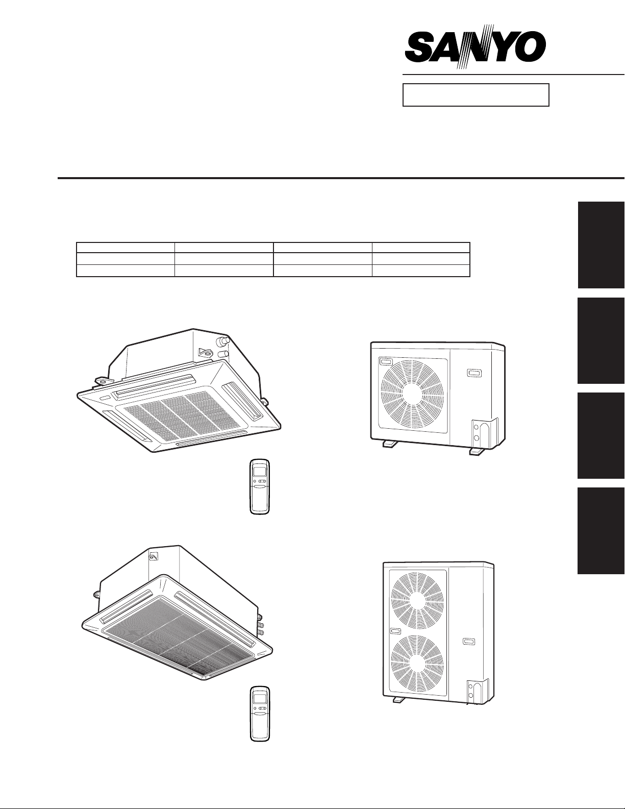
XHS2432 / CH2432
XHS3632 / CH3632
SPLIT SYSTEM AIR CONDITIONER
FILE NO.
Section
INDOOR MODEL No. PRODUCT CODE No. OUTDOOR MODEL No. PRODUCT CODE No.
XHS2432 854 013 40 CH2432 854 013 42
XHS3632 854 015 45 CH3632 854 014 57
Indoor Unit Outdoor Unit
XHS2432 CH2432
1
2
3
4
XHS3632 CH3632
85464849176000 REFERENCE NO. SM830076
Page 2
Important
Please Read Before Starting
This air conditioning system meets strict safety and operating
standards. As the installer or service person, it is an important
part of your job to install or service the system so it operates
safely and efficiently.
For safe installation and trouble-free operation, you must :
ⓦ Carefully read this instruction booklet before beginning.
ⓦ Follow each installation or repair step exactly as shown.
ⓦ Observe all local, state, and national electrical codes.
ⓦ Pay close attention to all warning and caution notices
given in this manual.
This symbol refers to a hazard or
unsafe practice which can result in
severe personal injury or death.
This symbol refers to a hazard or
CAUTION
unsafe practice which can result in
personal injury or product or
property damage.
If Necessary, Get Help
These instructions are all you need for most installation sites
and maintenance conditions. If you require help for a special
problem, contact our sales/service outlet or your certified dealer
for additional instructions.
In Case of Improper Installation
The manufacturer shall in no way be responsible for improper
installation or maintenance service, including failure to follow
the instructions in this document.
SPECIAL PRECAUTIONS
When Wiring
……………………………………………………………………
ELECTRICAL SHOCK CAN CAUSE SEVERE
PERSONAL INJURY OR DEATH. ONLY A
QUALIFIED, EXPERIENCED ELECTRICIAN
SHOULD ATTEMPT TO WIRE THIS SYSTEM.
• Do not supply power to the unit until all wiring and tubing are
completed or reconnected and checked.
• Highly dangerous electrical voltages are used in this system.
Carefully refer to the wiring diagram and these instructions
when wiring. Improper connections and inadequate grounding can cause accidental injury or death.
• Ground the unit following local electrical codes.
• Connect all wiring tightly. Loose wiring may cause overheating at connection points and a possible fire hazard.
When Transporting
……………………………………………………………………
Be careful when picking up and moving the indoor and outdoor
units. Get a partner to help, and bend your knees when lifting to
reduce strain on your back. Sharp edges or thin aluminum fins
on the air conditioner can cut your fingers.
When Installing
……………………………………………………………………
…In a Room
Properly insulate any tubing run inside a room to prevent
“sweating” that can cause dripping and water damage to walls
and floors.
…In Moist or Uneven Locations
Use a raised concrete pad or concrete blocks to provide a
solid, level foundation for the outdoor unit. This prevents water
damage and abnormal vibration.
…In an area with High Winds
Securely anchor the outdoor unit down with bolts and a metal
frame. Provide a suitable air baffle.
…In a Snowy Area (for Heat Pump-type Sys-tems)
Install the outdoor unit on a raised platform that is higher than
drifting snow. Provide snow vents.
When Connecting Refrigerant Tubing
……………………………………………………………………
• Ventilate the room well, in the event that refrigerant gas
leaks during the installation. Be careful not to allow contact
of the refrigerant gas with a flame as this will cause the
generation of poisonous gas.
• Keep all tubing runs as short as possible.
• Use the flare method for connecting tubing.
• Apply refrigerant lubricant to the matching surfaces of the
flare and union tubes before connecting them, then tighten
the nut with a torque wrench for a leak-free connection.
• Check carefully for leaks before starting the test run.
NOTE
Depending on the system type, liquid and gas lines may be
either narrow or wide. Therefore, to avoid confusion the
refrigerant tubing for your particular model is specified as either
“narrow” or “wide” rather than as “liquid” or “gas”.
When Servicing
……………………………………………………………………
• Turn the power OFF at the main power box (mains) before
opening the unit to check or repair electrical parts and
wiring.
• Keep your fingers and clothing away from any moving parts.
• Clean up the site when installation is finished. Check that no
metal scraps or bits of wiring have been left inside the unit.
CAUTION
• Ventilate any enclosed areas when installing or testing the
refrigeration system. Contact of refrigerant gas with fire or
heat can produce poisonous gas.
• Confirm after installation that no refrigerant gas is leaking. If
the gas comes in contact with a burning stove, gas water
heater, electric room heater or other heat source, it can
cause the generation of poisonous gas.
– 2 –
SM830076
Page 3

WHO SHOULD USE THIS MANUAL
This service manual is made to assist the service technician apply his knowledge and training
to this model air conditioner. This manual is written both for experienced service persons
and those who are new to air conditioning service. To help those with less experience or
who are new to this kind of unit we have included more explanations of basic procedures in
simple language than is usual in some service manuals. The experienced technician will of
course find he knows many of these things already and can go directly to the procedures and
information he needs; the less experienced technician will better understand what to do even
before he arrives on the job, and therefore be better able to work by himself as well as assist
the more experienced technician.
TABLE OF CONTENTS
1. SPECIFICATIONS.........................................................................................................6
1-1 Unit Specifications ................................................................................................7
1-2 Major Component Specifications ........................................................................11
(A)Indoor Unit .....................................................................................................11
(B)Outdoor Unit ..................................................................................................13
1-3 Other Component Specifications ........................................................................15
(A)Indoor Unit .....................................................................................................15
(B)Outdoor Unit ..................................................................................................17
1-4 Dimensional Data................................................................................................19
(A)Indoor Unit .....................................................................................................19
(B)Outdoor Unit ..................................................................................................21
1-5 Refrigerant Flow Diagram ...................................................................................23
1-6 Operating Range.................................................................................................23
2. PROCESSES AND FUNCTIONS ................................................................................25
2-1 Room Temperature Control ................................................................................26
(A)Cooling ..........................................................................................................26
(B)Heating ..........................................................................................................27
2-2 Cold Draft Prevention (Heating Cycle) ................................................................28
2-3 Automatic Fan Speed (Indoor Unit).....................................................................29
(A)Cooling ..........................................................................................................29
(B)Heating ..........................................................................................................29
2-4 Outdoor Fan Speed Control................................................................................30
(A)Cooling ..........................................................................................................30
(B)Heating ..........................................................................................................30
2-5 Freeze Prevention (Cooling) ...............................................................................31
2-6 Condensing Temperature Control (Cooling) ...................................................... 32
2-7 Overload Protection (Heating).............................................................................33
2-8 Discharge Temperature Control (Cooling and Heating)..................................... 34
– 3 –
SM830076
Page 4

2-9 Auto. Mode for Automatic Heating/Cooling Switching........................................ 35
2-10 Defrosting Control, Outdoor Heat Exchanger Coil (Heating).............................. 37
2-11 4-Way Valve, Solenoid Control ...........................................................................38
(A)Normal Control Mode ....................................................................................38
(B)AUTO Control Mode ......................................................................................39
2-12 Automatic Restart after Power Interruption ........................................................ 39
2-13 Electronic Expansion Valve ................................................................................40
2-14 Compressor Discharge Gas Temperature ......................................................... 40
(A)Cooling ..........................................................................................................40
(B)Heating (Except During Defrosting)...............................................................40
2-15 Compressor Current Detection Circuit ................................................................41
2-16 Electronic Expansion Valve Control ....................................................................42
2-17 Voltage Detection Control ...................................................................................43
3. ELECTRICAL DATA....................................................................................................45
3-1 Indoor Unit (Electric Wiring Diagram, Schematic Diagram) ............................... 46
3-2 Outdoor Unit (Electric Wiring Diagram, Schematic Diagram)............................. 48
4. SERVICE PROCEDURES ...........................................................................................53
4-1 Troubleshooting ..................................................................................................54
4-2 Checking the Electrical Components ..................................................................87
– 4 –
SM830076
Page 5

Introduction:
Read Me First!
This manual will help you understand and service the air conditioner. To help you find the information you need,
we have divided it into 5 main sections. Each section is divided into chapters with charts, tables and explanations to help you find and repair problems.
❑ Section 1: Specifications, tells you about the physical and electrical make up of the unit, as well
as its heating and cooling capacities. Look in this section to find the correct values for
components and functions.
❑ Section 2: Processes and Functions, explains each different part of the cooling and heating
cycle, and how each control function reacts to changing conditions to keep the room at the set
temperature range.
❑ Section 3: Electrical Data, which has fold-out schematic and wiring diagrams so you can find
the parts you need to check when something is wrong, and see how they should be connected.
❑ Section 4: Service Procedures, has two main parts, a
specific component to replace or adjust, and a chapter with specific procedures and values to
guide you in checking the electrical components in the unit.
WHAT IS IN THIS MANUAL
diagnostic
chapter to help you find the
HOW TO USE THIS MANUAL
You can use this manual both as a reference to find specific information about the capacity, functions and
construction of this unit, and as a source of information to help you set up and maintain the unit.
When this unit is not working properly, and the cause is not known, you can use the procedures in
Section 3: Servicing Procedures to find the problem, fix it, and restore the unit to its proper functioning.
This air conditioner has many helpful self diagnostic features to help you identify problem areas quickly.
So you will be ready when a problem happens, we suggest you look this manual over and become familiar with it
by following these steps:
1. Look at the TABLE OF CONTENTS to get an idea of what is in this manual and where to find it.
2. Look at the chapter about TROUBLE SHOOTING, so you are familiar with the way the flow
charts work. They are designed to guide you quickly through the possible causes for each kind of
problem that is likely to happen to the Unit. Particularly read the introduction to this section, and
the parts about the self-diagnosis and error codes which show on the display.
3. Look at the chapter about CHECKING ELECTRICAL COMPONENTS. You already know
about most of these procedures. This chapter gives you the specific values and methods for
these components. If you don’t know some of these procedures, you can easily learn them here.
4. Read the Instruction Manual! The Instruction Manual is included here because it helps you help
the user to set the temperature controls properly and know how to take care of any simple
problems that may happen, as well as know when to call for service. The Instruction Manual also
has illustrations, care, and installation information not found in the rest of the service manual. It is
short, and if you read it carefully, you will be able to answer the customers questions easily, and
also know the most efficient ways for setting times and temperatures.
Please use this manual to make your work easier, keep the air conditioner functioning well, and keep your
customers satisfied.
– 5 –
SM830076
Page 6

1. SPECIFICATIONS
1-1 Unit Specifications ...........................................................................................7
1-2 Major Component Specifications .................................................................. 11
(A)Indoor Unit ................................................................................................ 11
(B)Outdoor Unit .............................................................................................13
1-3 Other Component Specifications .................................................................. 15
(A)Indoor Unit ................................................................................................ 15
(B)Outdoor Unit .............................................................................................17
1-4 Dimensional Data...........................................................................................19
(A)Indoor Unit ................................................................................................ 19
(B)Outdoor Unit .............................................................................................21
1-5 Refrigerant Flow Diagram ............................................................................. 23
1-6 Operating Range............................................................................................23
1
– 6 –
SM830076
Page 7
1. Specifications
1-1 Unit Specifications
MODEL No. Indoor Unit XHS2432
Outdoor Unit CH2432
POWER SOURCE 230 - 208 V / 1 Phase / 60 Hz
PERFORMANCE Cooling Heating
Capacity* BTU / h 24,000 23,400 25,000 24,300
Moisture removal (High) Pints / h 8.6 8.4 —
Air circulation (Hi)
S.E.E.R. (H.S.P.F.)
ELECTRICAL RATINGS
Voltage rating VAC 230 208 230 208
Available voltage range VAC 187 - 253 187 - 253
Running amperes A 11.2 11.6 11.7 12.3
Max. running amperes A — — — —
Power input* W 2,450 2,350 2,500 2,450
Buck-up heater kW — — — —
Maximum fuse size A 30
FEATURES
Controls Microprocessor
Fan speeds Indoor / Outdoor 3 and Automatic control / 2 (Auto)
Timer ON / OFF 24-hours & Program
Air deflection Horizontal / Vertical — / Automatic
Air filter Washable, easy access, long life fiter (2,500 hr)
Operation sound Indoor dB - A 37 / 35 / 31
Hi / Me / Lo Outdoor - Hi dB - A 53
Refrigerant control Electronic Refrigerant Control Valve
REFRIGERANT PIPING
Limit of piping length ft. (m) 165 (50)
Limit of piping length at shipment ft. (m) 100 (30)
Limit of elevation difference ft. (m) Outdoor unit is higher than indoor unit: 165 (50)
between the two units Outdoor unit is lower than indoor unit: 100 (30)
Refrigerant piping Narrow pipe in. (mm) 1 / 4 (6.35)
Flare type Wide pipe in. (mm) 3 / 4 (19.05)
(17°F)** 16,400 15,800
cu.ft. / min.
BTU / Wh
(17°F)** 2,150 2,020
10.0 10.2 (7.0) (7.0)
540 / 510
1
2
3
– 7 –
4
SM830076
Page 8

1
2
1. Specifications
1-1 Unit Specifications
DIMENSIONS & WEIGHT Indoor unit Outdoor unit
Unit dimensions Height in. (mm) 9-27/32 (250) 28-30/32 (735)
Width in. (mm) 29-29/32 (760) 37 (940)
Depth in. (mm) 29-29/32 (760) 13-12/32 (340)
Net weight lbs. (kg) 49 (22) 157 (71)
Indoor grille dimensions Height in. (mm) 3-1/16 (78)
PNR-XHS2432 Width in. (mm) 33-27/32 (860)
Depth in. (mm) 33-27/32 (860)
Net weight lbs. (kg) 11 (5)
Indoor / Outdoor unit Height in. (mm) 11-6/32 (284) 32-17/32 (826)
Package dimensions Width in. (mm) 32-14/32 (824) 40 (1,016)
Depth in. (mm) 32-25/32 (833) 16-12/32 (416)
Shipping weight lbs. (kg) 60 (27) 170 (77)
Shipping volume cu.ft. (m3) 6.9 (0.195) 12.3 (0.349)
Indoor grille Height in. (mm) 4-3/32 (104)
Package dimensions Width in. (mm) 38-2/32 (967)
PNR-XHS2432 Depth in. (mm) 39-11/32 (999)
Shipping weight lbs. (kg) 18 (8)
Shipping volume cu.ft. (m3) 3.5 (0.100)
Cooling :
Rating conditions (*) : Room temperature 80 °F DB / 67 °F WB, Ambient temperature 95 °F DB / 75 °F WB
Heating :
Rating conditions (*) : Room temperature 70 °F DB / 60 °F WB, Ambient temperature 47 °F DB / 43 °F WB
Low temp conditions (**): Room temperature 70 °F DB / 60 °F WB, Ambient temperature 17 °F DB / 15 °F WB
DATA SUBJECT TO CHANGE WITHOUT NOTICE
3
4
– 8 –
SM830076
Page 9

1. Specifications
1-1 Unit Specifications
MODEL No. Indoor Unit XHS3632
Outdoor Unit CH3632
POWER SOURCE 230 - 208 VAC / 1 Phase / 60 Hz
PERFORMANCE Cooling Heating
Capacity* BTU / h 34,500 33,500 37,500 36,500
Moisture removal (High) Pints / h 11.1 11.1 —
Air circulation (Hi)
S.E.E.R. (H.S.P.F.)
ELECTRICAL RATINGS
Voltage rating VAC 230 208 230 208
Available voltage range VAC 187 - 253 187 - 253
Running amperes A 15.4 15.8 18.2 19.3
Max. running amperes A — — — —
Power input* W 3,350 3,200 3,850 3,750
Buck-up heater kW — — — —
Maximum fuse size A 30
FEATURES
Controls Microprocessor
Fan speeds Indoor / Outdoor 3 and Automatic control / 2 (Auto)
Timer ON / OFF 24-hours & Program
Air deflection Horizontal / Vertical — / Automatic
Air filter Washable, easy access, long life fiter (2,500 hr)
Operation sound Indoor dB - A 43 / 40 / 36
Hi / Me / Lo Outdoor - Hi dB - A 56
Refrigerant control Electronic Refrigerant Control Valve
REFRIGERANT PIPING
Limit of piping length ft. (m) 165 (50)
Limit of piping length at shipment ft. (m) 100 (30)
Limit of elevation difference ft. (m) Outdoor unit is higher than indoor unit: 165 (50)
between the two units Outdoor unit is lower than indoor unit: 100 (30)
Refrigerant piping Narrow pipe in. (mm) 3 / 8 (9.52)
Flare type Wide pipe in. (mm) 3 / 4 (19.05)
(17°F)** 25,000 23,500
cu.ft. / min.
BTU / Wh
(17°F)** 3,150 2,950
10.7 11.0 (7.0) (7.0)
980 / 880
1
2
3
– 9 –
4
SM830076
Page 10
1
2
1. Specifications
1-1 Unit Specifications
DIMENSIONS & WEIGHT Indoor unit Outdoor unit
Unit dimensions Height in. (mm) 11-1/32 (280) 48-20/32 (1,235)
Width in. (mm) 41-11/32 (1,050) 37 (940)
Depth in. (mm) 29-29/32 (760) 13-12/32 (340)
Net weight lbs. (kg) 60 (27) 203 (92)
Indoor grille dimensions Height in. (mm) 3-1/6 (78)
PNR-XHS3632 Width in. (mm) 33-27/32 (1,150)
Depth in. (mm) 33-27/32 (860)
Net weight lbs. (kg) 15 (7)
Indoor / Outdoor unit Height in. (mm) 12-14/32 (316) 52-7/32 (1,326)
Package dimensions Width in. (mm) 43-27/32 (1,114) 40 (1,016)
Depth in. (mm) 32-25/32 (833) 16-12/32 (416)
Shipping weight lbs. (kg) 71 (32) 227 (103)
Shipping volume cu.ft. (m3) 10.3 (0.293) 19.8 (0.56)
Indoor grille Height in. (mm) 4-3/32 (104)
Package dimensions Width in. (mm) 49-16/32 (1,257)
PNR-XHS3632 Depth in. (mm) 39-11/32 (999)
Shipping weight lbs. (kg) 29 (13)
Shipping volume cu.ft. (m3) 4.6 (0.131)
Cooling :
Rating conditions (*) : Room temperature 80 °F DB / 67 °F WB, Ambient temperature 95 °F DB / 75 °F WB
Heating :
Rating conditions (*) : Room temperature 70 °F DB / 60 °F WB, Ambient temperature 47 °F DB / 43 °F WB
Low temp conditions (**): Room temperature 70 °F DB / 60 °F WB, Ambient temperature 17 °F DB / 15 °F WB
DATA SUBJECT TO CHANGE WITHOUT NOTICE
3
4
– 10 –
SM830076
Page 11

1. Specifications
1-2 Major Component Specifications
(A) Indoor Unit
MODEL No. XHS2432
Source 230 - 208 VAC / 1 phase / 60 Hz
Remote controller (Accessory) RCS - 5HPS4U
Controller P. C. B Ass'y CR - THS2432
Control circuit fuse 250 VAC, 3 A
Controller Ass'y CR - 3XHS
Fan (Number … diameter) in. (mm) Turbo (1…19-9/32 (490))
Fan motor
Model SFG6X - 41A5P
Source 230 - 208 V / 1 phase / 60 Hz
No. of pole … r.p.m. (230 V, High) rpm 6 … 451
Nominal output W 40
Coil resistance Ω BRW - WHT : 114.0 , ORG - YEL : 66.4
(Ambient temperature 68 °F) WHT - VLT : 23.9 , WHT - PNK : 77.4
VLT - ORG : 12.4 , YEL - BLK : 82.1
Safety device
Operating temperature Open °F266± 14.4
Close °F 174.2 ± 27
Run capacitor VAC, µF 440 V , 4 µF
Electronic expansion valve
Coil DKV - MOZS582E0
Coil resistance (at 20°C) Ω ORG - GRY : 46 , YEL - GRY : 46
RED - GRY : 46 , BLK - GRY : 46
Valve body IKV - 24D12
Heat exchanger
Coil Aluminum plate fin / Copper tube
Rows … Fins per inch 2 … 14.9
Face area ft.
Panel
Model No. PNR - XHS2432
Indicator Lamp Ass'y IND - 3THS
Auto louver motor MT8 - 3C
Auto louver motor … Rated V, W, rpm 240 VAC , 3 W , 3 rpm
Coil resistance (Ambient temperature 77 °F) Ω 16.430 Ω ± 8 %
2
(m2) 3.18 (0.295)
DATA SUBJECT TO CHANGE WITHOUT NOTICE
1
2
3
4
– 11 –
SM830076
Page 12
1
2
3
4
1. Specifications
1-2 Major Component Specifications
(A) Indoor Unit
MODEL No. XHS3632
Source 230 - 208 VAC / 1 phase / 60 Hz
Remote controller (Accessory) RCS - 5HPS4U
Controller P. C. B Ass'y CR - THS2432
Control circuit fuse 250 VAC, 3 A
Controller Ass'y CR - 3XHS
Fan (Number … diameter) in. (mm) Turbo (1…19-9/32 (490))
Fan motor
Model SFG6X - 61A3P
Source 230 - 208 V / 1 phase / 60 Hz
No. of pole … r.p.m. (230 V, High) rpm 6 … 560
Nominal output W 60
Coil resistance Ω BRW - WHT : 71.1 , ORG - YEL : 22.7
(Ambient temperature 68 °F) WHT - VLT : 8.7 , VLT - PNK : 43.2
VLT - ORG : 13.3 , YEL - BLK : 54.32
Safety device
Operating temperature Open °F266± 14.4
Close °F 174.2 ± 27
Run capacitor VAC, µF 440 V , 6 µF
Electronic expansion valve
Coil EKV - MOZS584E0
Coil resistance (at 20°C) Ω ORG - GRY : 46 , YEL - GRY : 46
RED - GRY : 46 , BLK - GRY : 46
Valve body HKV - 30D16
Heat exchanger
Coil Aluminum plate fin / Copper tube
Rows … Fins per inch 2 … 14.9
Face area ft.
Panel
Model No. PNR - XHS3632
Indicator Lamp Ass'y IND - 3THS
Auto louver motor MT8 - 3C
Auto louver motor … Rated V, W, rpm 240 VAC , 3 W , 3 rpm
Coil resistance (Ambient temperature 77 °F) Ω 16.430 Ω ± 8 %
2
(m2) 5.17 (0.48)
DATA SUBJECT TO CHANGE WITHOUT NOTICE
– 12 –
SM830076
Page 13
1-2 Major Component Specifications
(B) Outdoor Unit
MODEL No. CH2432
Source 230 - 208 VAC / 1 phase / 60 Hz
Controller P.C.B. Ass'y CR - CH2432 (Microprocessor)
Control circuit fuse 250 VAC, 3 A
Compressor Rotary (Hermetic)
Model C - 2R160H6T
Source 230 - 208 VAC / 1 phase / 60 Hz
Nominal output W 1,700
Compressor oil cc 800
Coil resistance (Ambient temperature 77 °F) Ω C – R : 0.885 , C – S : 1.773
Safety device Internal type
Overload relay models —
Operating temperature Open °F 297 ± 9
Close °F 198 ± 20
Operating ampere (at 77 °F) A —
Run capacitor VAC, µF 400 VAC, 40 µF
Crank case heater VAC, W 230 VAC, 30 W
Refrigerant amount charged at shipment lbs. (kg) R22 : 6.17 (2.8)
High pressure switch ACB-1UB11
Set pressure OFF lb/in2(kg/cm2) 426.6 (30 )
ON lb/in2(kg/cm2) 341.3 ± 28.44 (24 ± 2.0)
Fan Propeller
Number...diameter in. (mm) 1 ... 18 - 3/32 (460)
Fan speeds 2 (AUTO)
Fan motor
Model KFC6T - 91D6P
Source 230 - 208 VAC / 1 phase / 60 Hz
No. of pole ..... rpm (230 V, High) 6 ... 879
Nominal output W 110
Coil resistance Ω BRN – WHT : 67.14 , VLT – YEL : 11.42
(Ambient temperature 68 °F) WHT – VLT : 64.85 , YEL – PNK : 10.60
Safety device Internal type
Operating temperature Open °F 248 ± 9
Close °F 171 ± 27
Run capacitor VAC, µF 440 VAC, 4 µF
Heat exchange
Coil Aluminum plate fin / Copper tube
Rows ..... Fins per inch 2 ... 14.1
Face area ft.
2
(m2) 6.78 (0.63)
+ 28.44
+ 7.11
DATA SUBJECT TO CHANGE WITHOUT NOTICE
+ 2.0
+ 0.5
1. Specifications
1
2
3
4
– 13 –
SM830076
Page 14
1
2
3
4
1-2 Major Component Specifications
(B) Outdoor Unit
MODEL No. CH3632
Source 230 - 208 VAC / 1 phase / 60 Hz
Controller P.C.B. Ass'y CR - CH2432 (Microprocessor)
Control circuit fuse 250 V, 3 A
Compressor Rotary (Hermetic)
Model C - R221H6R
Source 230 - 208 VAC / 1 phase / 60 Hz
Nominal output W 2,200
Compressor oil cc 1,500
Coil resistance (Ambient temperature 77 °F) Ω C – R : 0.549 , C – S : 1.525
Safety device Internal type
Overload relay models —
Operating temperature Open °F 320 ± 9
Close °F 189 ± 20
Operating ampere (at 77 °F) A —
Run capacitor VAC, µF 400 VAC, 40 µF
Crank case heater VAC, W 230 VAC, 30 W
Refrigerant amount charged at shipment lbs. (kg) R22 : 8.82 (4.0)
High pressure switch ACB-1UB11
Set pressure OFF lb/in2(kg/cm2) 426.6 (30 )
ON lb/in2(kg/cm2) 341.3 ± 28.44 (24 ± 2.0)
Fan Propeller
Number...diameter in. (mm) 2 ... 18 - 3/32 (460)
Fan speeds 2 (AUTO)
Fan motor
Model KFC6T - 91D6P × 2
Source 230 - 208 V / 1 phase / 60 Hz
No. of pole ..... rpm (230 V, High) 6 ... 879
Nominal output W 110 × 2
Coil resistance Ω BRN – WHT : 67.14 , VLT – YEL : 11.42
(Ambient temperature 68 °F) WHT – VLT : 64.85 , YEL – PNK : 10.60
Safety device Internal type
Operating temperature Open °F 248 ± 9
Close °F 171 ± 27
Run capacitor VAC, µF 440 VAC, 4 µF × 2
Heat exchange
Coil Aluminum plate fin / Copper tube
Rows ..... Fins per inch 2 ... 14.1
Face area ft.
2
(m2) 11.63 (1.08)
+ 28.44
+ 7.11
DATA SUBJECT TO CHANGE WITHOUT NOTICE
+ 2.0
+ 0.5
1. Specifications
– 14 –
SM830076
Page 15

1. Specifications
1-3 Other Component Specifications
(A) Indoor Unit
MODEL No. XHS2432
Power Transformer ATR – II174B
Rated Primary 220 VAC, 60 Hz
Secondary 14.8 VAC 0.55 mA, 14.8 VAC 0.6 mA
Capacity —
Coil resistance
(Ambient temprature 77 °F)
Thermistor cut off temperature °F277
Thermistor (Coil sensor) : TH2, 3 PBC - 41E - S26
Coil resistance kΩ 14 °F : 23.7 , 41 °F : 12.1
Thermistor (Room sensor) : TH1 KTEC - 35 - S6
Coil resistance kΩ 32 °F : 16.5 , 104 °F : 2.7
Drain pump WP20SL - 21
Rated 230 / 208 VAC, 12.5 W
Float switch FS - 0218 - 102
MAX Rated (Contact rated) 50 W, DC 5V, 0.1 mA
Solenoid control valve or coil
Solenoid control valve IKV - 24D12
Solenoid coil DKV - MOZS582E0
Indicator Lamp Ass'y IND - 3THS
Synchronized Motor MT8 - 3C
Ω WHT - WHT : 101 , BRN - BRN : 0.42
23 °F : 18.8 , 50 °F : 9.7
32 °F : 15.0 , 59 °F : 8.0
41 °F : 12.8 , 113 °F : 2.2
50 °F : 10.0 , 122 °F : 1.8
68 °F : 6.3 , 131 °F : 1.5
86 °F : 4.0 ,
1
2
3
– 15 –
4
SM830076
Page 16
1
2
3
1. Specifications
1-3 Other Component Specifications
(A) Indoor Unit
MODEL No. XHS3632
Power Transformer ATR – II174B
Rated Primary 220 VAC, 60 Hz
Secondary 14.8 VAC 0.55 mA, 14.8 VAC 0.6 mA
Capacity —
Coil resistance
(Ambient temprature 77 °F)
Thermistor cut off temperature °F277
Thermistor (Coil sensor) : TH2, 3 PBC - 41E - S36
Coil resistance kΩ 14 °F : 23.7 , 41 °F : 12.1
Thermistor (Room sensor) : TH1 KTEC - 35 - S6
Coil resistance kΩ 32 °F : 16.5 , 104 °F : 2.7
Drain pump WP20SL - 21
Rated 230 / 208 VAC, 12.5 W
Float switch FS - 0218 - 103
MAX Rated (Contact rated) 50 W, DC 5V, 0.1 mA
Solenoid control valve or coil
Solenoid control valve HKV - 30D16
Solenoid coil EKV - MOZS728E0
Indicator Lamp Ass'y IND - 3THS
Synchronized Motor MT8 - 3C
Ω WHT - WHT : 101 , BRN - BRN : 0.42
23 °F : 18.8 , 50 °F : 9.7
32 °F : 15.0 , 59 °F : 8.0
41 °F : 12.8 , 113 °F : 2.2
50 °F : 10.0 , 122 °F : 1.8
68 °F : 6.3 , 131 °F : 1.5
86 °F : 4.0 ,
DATA SUBJECT TO CHANGE WITHOUT NOTICE
4
– 16 –
SM830076
Page 17
1. Specifications
1-3 Other Component Specifications
(B) Outdoor Unit
MODEL No. CH2432
Compressor Motor Magnetic Contactor FMCA - 1UL
Coil rated 240 VAC, 60 Hz
Coil resistance (at 77 °F) Ω 580 ± 15 %
Contact rated (Main) 230 VAC, 20 A
Contact rated (Auxiliary) 230 VAC, 3 A
Power Relay HH62S
Coil rated 240 VAC, 60 Hz
Coil resistance (at 77 °F) kΩ 17.2
Contact rated 220 VAC, 5 A
Power Transformer ATR - I65C
Rated
Primary 220 VAC, 60 Hz
Secondary 14 V, 0.4 A
Capacity 5.6 VA
Coil resistance (at 73 °F ) Ω WHT – WHT : 395.5 , BRN – BRN : 2.19
Thermal cut off temperature °F266
Thermistor (Coil sensor) : TH6, 7
Coil resistance kΩ 14 °F : 23.7 , 50 °F : 9.7
Thermistor (Comp. discharge gas sensor) : TH8
Coil resistance kΩ 140 °F : 13.8 , 194 °F : 5.1
Solenoid control valve or coil
Solenoid control valve V 389100
Solenoid coil LB 59005
Thermistor (PTC) TDK – 101YV
Rated
Max. voltage 400 VAC
Max. ampere 11.5 A
Resistance (at 77 °F) Ω 100 %
PBC - 41E - S4 , PBC - 41E - S26
23 °F : 18.8 , 68 °F : 6.5
32 °F : 15.0 , 86 °F : 4.4
41 °F : 12.1 , 104 °F : 3.1
113 °F : 2.6
PTC - 51H - S1
158 °F : 9.7 , 212 °F : 3.8
167 °F : 8.2 , 230 °F : 2.8
176 °F : 7.0 , 248 °F : 2.2
185 °F : 5.9 , 266 °F : 1.7
+ 30
– 20
DATA SUBJECT TO CHANGE WITHOUT NOTICE
1
2
3
4
– 17 –
SM830076
Page 18
1
2
3
4
1. Specifications
1-3 Other Component Specifications
(B) Outdoor Unit
MODEL No. CH3632
Compressor Motor Magnetic Contactor FMCA - 1SUL
Coil rated 240 VAC, 60 Hz
Coil resistance (at 68 °F) Ω 588 ± 10 %
Contact rated (Main) 240 VAC, 26 A
Contact rated (Auxiliary) 240 VAC, 3 A
Power Relay HH62S
Coil rated 240 VAC, 60 Hz
Coil resistance (at 77 °F) kΩ 17.2
Contact rated 220 VAC, 5 A
Power Transformer ATR - I65C
Rated
Primary 220 VAC, 60 Hz
Secondary 14 V, 0.4 A
Capacity 5.6 VA
Coil resistance (at 73 °F ) Ω WHT – WHT : 395.5 , BRN – BRN : 2.19
Thermal cut off temperature °F266
Thermistor (Coil sensor) : TH6, 7
Coil resistance kΩ 14 °F : 23.7 , 50 °F : 9.7
Thermistor (Comp. discharge gas sensor) : TH8
Coil resistance kΩ 140 °F : 13.8 , 194 °F : 5.1
Solenoid control valve or coil
Solenoid control valve V 389100
Solenoid coil LB 59005
Thermistor (PTC) TDK – 101YV
Rated
Max. voltage 400 VAC
Max. ampere 11.5 A
Resistance (at 77 °F) Ω 100 %
PBC - 41E - S4 , PBC - 41E - S36
23 °F : 18.8 , 68 °F : 6.5
32 °F : 15.0 , 86 °F : 4.4
41 °F : 12.1 , 104 °F : 3.1
113 °F : 2.6
PTC - 51H - S1
158 °F : 9.7 , 212 °F : 3.8
167 °F : 8.2 , 230 °F : 2.8
176 °F : 7.0 , 248 °F : 2.2
185 °F : 5.9 , 266 °F : 1.7
+ 30
– 20
DATA SUBJECT TO CHANGE WITHOUT NOTICE
– 18 –
SM830076
Page 19
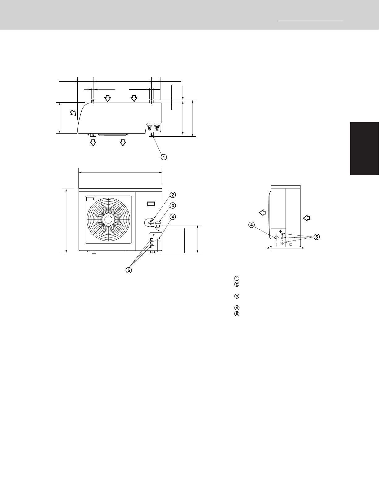
1-4 Dimensional Data
(A) Indoor Unit: XHS2432
4-29/32
1. Specifications
8-21/32
8-1/16
• Remote controller (Accessory)
X-view
14
13-3/8
4-29/32
5-29/32
7-7/8
10-1/32
32-9/32 (Ceiling opening)
23-7/32 (Suspention bolt pitch)
14
12
X
Grille center
13-2/4 1-3/8
32-9/32 (Ceiling opening)
28-3/4(Suspention bolt pitch)
11-23/32 1-3/16
8-1/16
6-1/2
1-7/8
3-15/16
29-29/32
3-15/16
19/32
1/2
1/2
33-27/32
19-11/16
2-13/32 23/32
33-27/32
19-11/16
6-25/32
1
2
3
4
Min. 2-3/8
3-1/32
4-29/32
29-29/32
– 19 –
1/2
1/2
Dimension : inch
Air intake
Air outlet
Narrow tube (1/4")
Wide tube (3/4")
Drain connection
Power line (conduit size : 1/2")
For discharge duct
Suspention bolt mounting
1024_X_S
SM830076
Page 20
1-4 Dimensional Data
(A) Indoor Unit: XHS3632
8-19/32
1. Specifications
1
2
3
2-13/32
32-9/32 (Ceiling opening)
23-7/32 (Suspention bolt pitch)
13-15/32 19/32
X-view
19-9/32 1-9/16
5-23/321-3/8
29-29/32
2-3/4
8-9/32
6-1/2
11-7/32
12-29/32
8-19/32
4-29/32
2-3/8
1-3/16
15/32
33-27/32
19-11/16
4
Panel center
41-11/32
43-11/16 (Ceiling opening)
40-5/32 (Suspention bolt pitch)
9
3-15/16 3-15/16
1-7/8
8-9/32
45-9/32
31-3/32
15/32
Dimension : inch
Air intake grille
Air outlet
Refrigerant liquid line (ø3/8")
Refrigerant gas line (ø3/4")
Drain connection
Power supply entry
For discharge duct
Humidifier (option) mounting hole
Suspension bolt mounting
1346_X_S
– 20 –
SM830076
Page 21
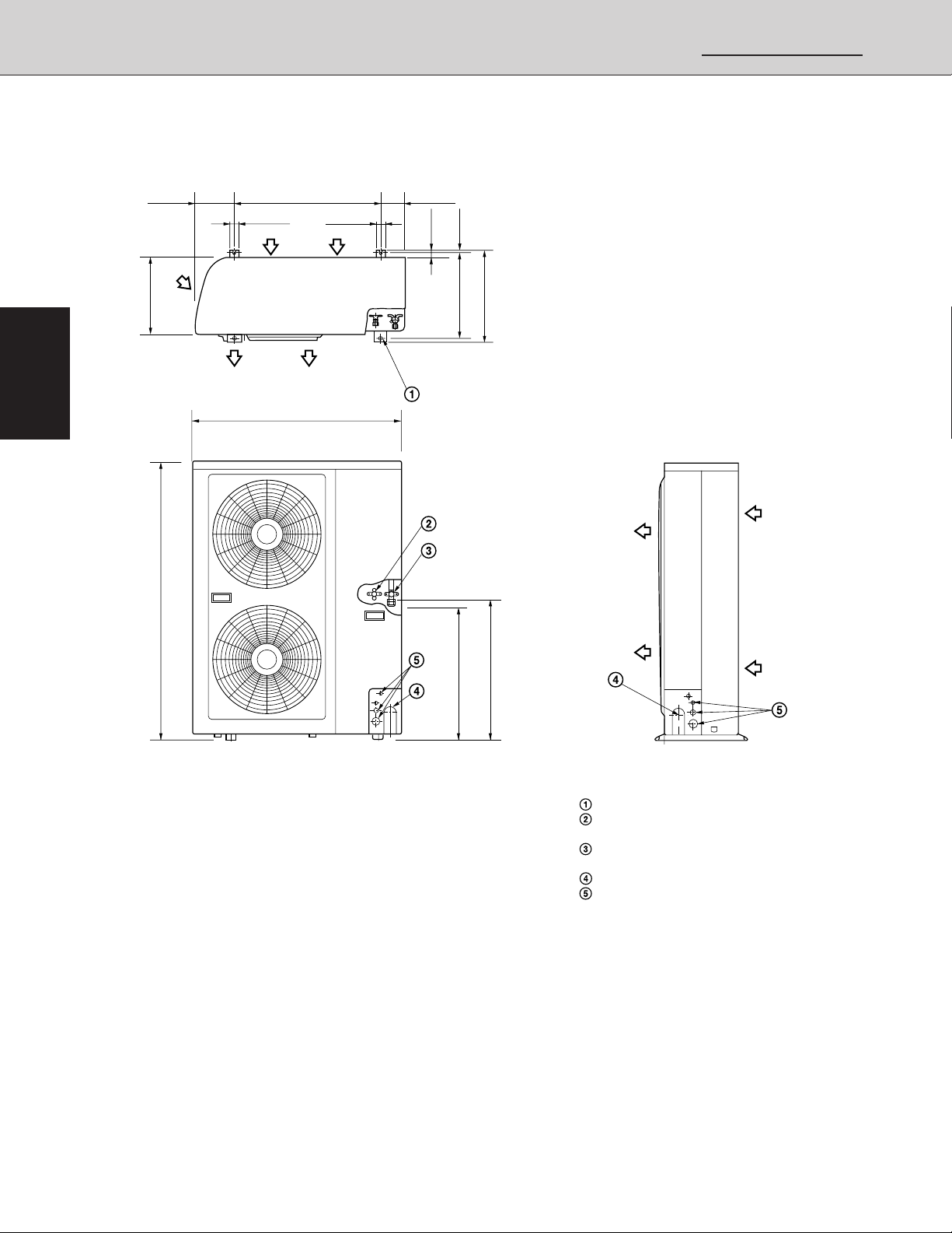
1-4 Dimensional Data
(B) Outdoor Unit: CH2432
1-31/32
1. Specifications
4-21/64266-11/16
1-31/32
1-3/16
13-3/8
28-15/16
37
14-31/32 13/32
11
15-3/4
12-1/16
Dimension : inch
Hole for anchor bolt (4-ø1/2)
Refrigerant tube joint (narrow tube)
Flare connection 1/4 in (6.35 mm)
Refrigerant tube joint (wide tube)
Flare connection 3/4 in (19.05 mm)
Refrigerant tubing inlet
Power supply inlet
1131_THS_I
1
2
3
4
– 21 –
SM830076
Page 22
1-4 Dimensional Data
(B) Outdoor Unit: CH3632
1-31/32 1-31/32
1. Specifications
4-21/64266-11/16
1-3/16
1
2
3
13-3/8
48-5/8
37
15-3/4
14-31/32 13/32
22-27/32
23-29/32
4
– 22 –
Dimension : inch
Hole for anchor bolt (4-ø13)
Refrigerant tube joint (narrow tube)
Flare connection 3/8 in (9.52 mm)
Refrigerant tube joint (wide tube)
Flare connection 3/4 in (19.05 mm)
Refrigerant tubing inlet
Power supply inlet
1581_C_S
SM830076
Page 23
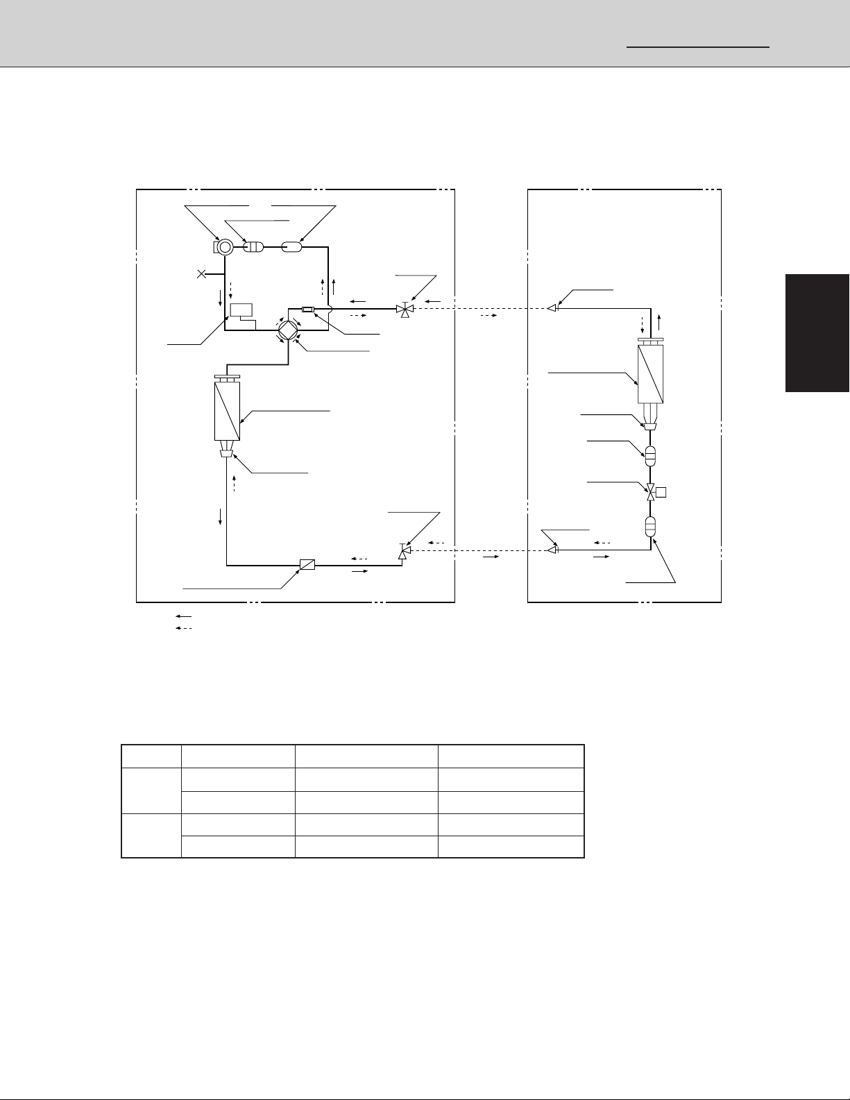
1-5 Refrigerant Flow Diagram
Outdoor Unit: CH2432 Indoor Unit: XHS2432
1. Specifications
Compressor
Accumulator
High
pressure
switch
Sub-heat exchanger
HP
EC
P
Cooling Cycle
Heating Cycle
Accumulator
4-way valve
Heat exchanger
Distributor
Muffler
Gas line
service
valve
Liquid line
service
valve
O.D.
3/4"
(19.05mm)
O.D.
1/4"
(6.35mm)
Gas line
nipple
Heat exchanger
Distributor
Strainer
Electronic
ref.control
valve
Liquid line
nipple
1
EC
P
2
M
Strainer
3
1132_THS_I
1-6 Operating Range
Temperature Indoor Air Intake Outdoor Air Intake
Cooling
Heating
Maximum 95 °F DB, 71 °F WB 115 °F DB
Minimum 67 °F DB, 57 °F WB 23 °F DB
Maximum 80 °F DB, 67 °F WB 75 °F DB, 65 °F WB
Minimum -DB / -WB 17 °F DB / 15 °F WB
4
SM830076
– 23 –
Page 24
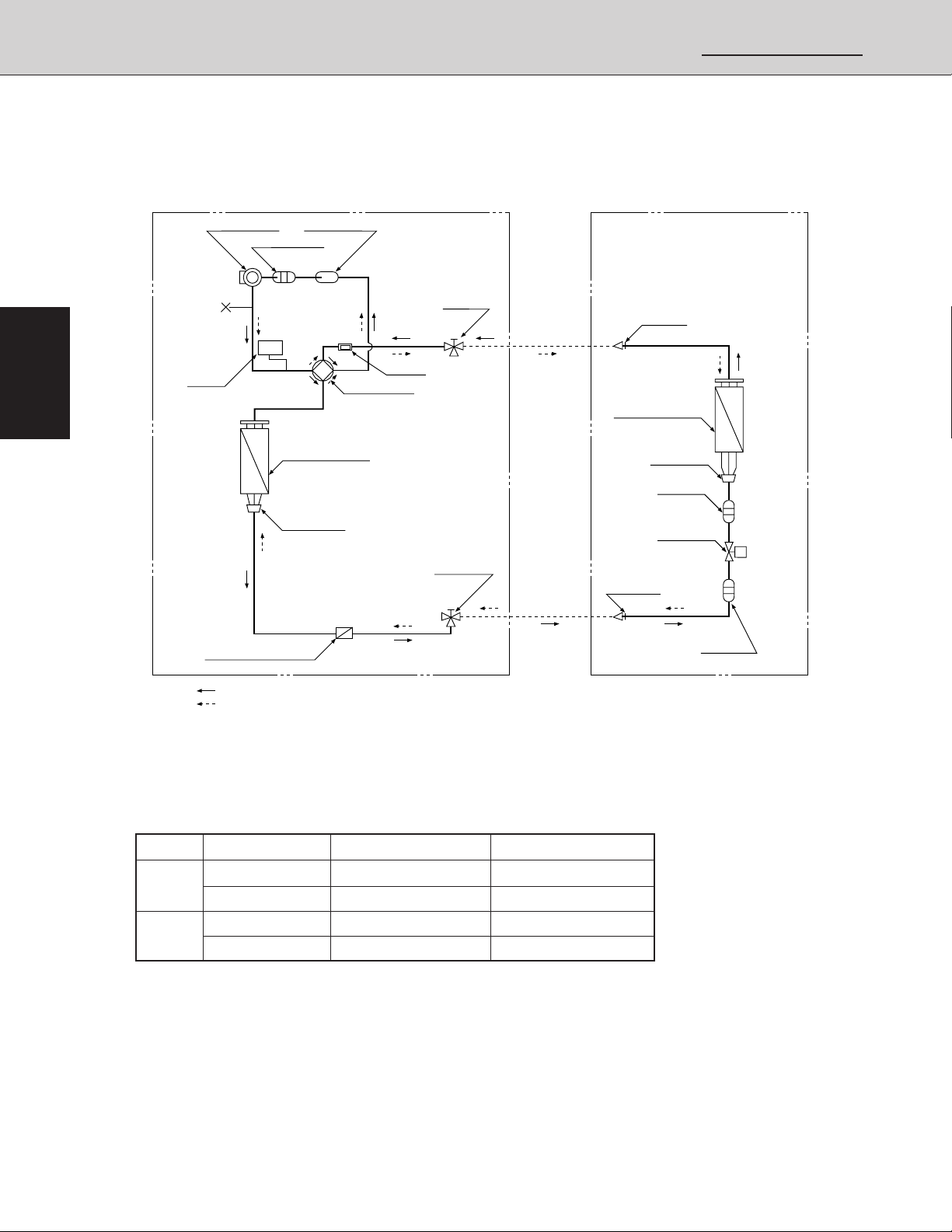
1-5 Refrigerant Flow Diagram
Outdoor Unit: CH3632 Indoor Unit: XHS3632
1. Specifications
1
2
3
Compressor
Accumulator
High
pressure
switch
Sub-heat exchanger
HP
EC
P
Cooling Cycle
Heating Cycle
Accumulator
4-way valve
Heat exchanger
Distributor
Muffler
Gas line
service
valve
Liquid line
service
valve
O.D.
3/4"
(19.05mm)
O.D.
3/8"
(9.52mm)
Gas line
nipple
Heat exchanger
Distributor
Strainer
Electronic
ref.control
valve
Liquid line
nipple
EC
P
M
Strainer
1398_THS_I
4
1-6 Operating Range
Temperature Indoor Air Intake Outdoor Air Intake
Cooling
Heating
Maximum 95 °F DB, 71 °F WB 115 °F DB
Minimum 67 °F DB, 57 °F WB 23 °F DB
Maximum 80 °F DB, 67 °F WB 75 °F DB, 65 °F WB
Minimum -DB / -WB 17 °F DB / 15 °F WB
– 24 –
SM830076
Page 25

2. Processes and functions
1. Specifications
2. PROCESSES AND FUNCTIONS
2-1 Room Temperature Control .......................................................................... 26
(A)Cooling .....................................................................................................26
(B)Heating .....................................................................................................27
2-2 Cold Draft Prevention (Heating Cycle) .......................................................... 28
2-3 Automatic Fan Speed (Indoor Unit)............................................................... 29
(A)Cooling .....................................................................................................29
(B)Heating .....................................................................................................29
2-4 Outdoor Fan Speed Control.......................................................................... 30
(A)Cooling .....................................................................................................30
(B)Heating .....................................................................................................30
2-5 Freeze Prevention (Cooling) ......................................................................... 31
2-6 Condensing Temperature Control (Cooling) ................................................. 32
2-7 Overload Protection (Heating)....................................................................... 33
2-8 Discharge Temperature Control (Cooling and Heating)................................ 34
2-9 Auto. Mode for Automatic Heating/Cooling Switching................................... 35
2-10 Defrosting Control, Outdoor Heat Exchanger Coil (Heating)......................... 37
2-11 4-Way Valve, Solenoid Control ..................................................................... 38
(A)Normal Control Mode ...............................................................................38
(B)AUTO Control Mode .................................................................................39
2-12 Automatic Restart after Power Interruption ................................................... 39
2-13 Electronic Expansion Valve .......................................................................... 40
2-14 Compressor Discharge Gas Temperature .................................................... 40
(A)Cooling .....................................................................................................40
(B)Heating (Except During Defrosting) ......................................................... 40
2-15 Compressor Current Detection Circuit .......................................................... 41
2-16 Electronic Expansion Valve Control .............................................................. 42
2-17 Voltage Detection Control ............................................................................. 43
Section
1
2
3
4
– 25 –
SM830076
Page 26
Section
1
2. Processes and functions
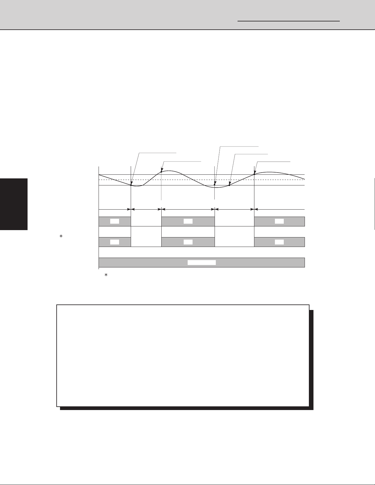
2-1 Room Temperature Control
The Unit adjusts room temperature by turning the outdoor unit’s compressor ON and OFF.
This process is controlled by the thermostat located in the remote control unit.
The figures on this and the next pages show how each part of the system performs when the
room temperature changes and the thermostat activates the compressor to start (thermo ON)
or stop (thermo OFF). Fig. 1 shows about the cooling cycle, and Fig. 2 shows about the
heating cycle.
(A) Cooling
THERMO. OFF
(THERMO. ON)
(THERMO. OFF)
ROOM TEMP.
THERMO. ON
2
3
4
BODY SENSOR
SET TEMP
COMPRESSOR
OUTDOOR FAN
T+2 °F
. T °F
T–2 °F
1
(H OR M)
INDOOR FAN
MORE THAN
5 MINUTES
ON ON ON
ON ON ON
1. Refer to 2-4 Outdoor Fan Speed Control
3 MINUTES
OFF OFF
OFF OFF
5 MINUTES
SET SPEED
MORE THAN
3 MINUTES
MORE THAN
5 MINUTES
Fig. 1
Chart Summary and Explanations
❑ Once the compressor starts, it keeps running for 5 minutes.
❑ Once the compressor stops, it will not start running again for 3 minutes.
❑ If you change the operation mode (HEAT, COOL, or FAN) during the cooling cycle, the
control circuit stops the compressor for 3 minutes.
❑ For 5 minutes after the compressor is first turned on, and for 3 minutes after it is turned off,
the compressor is not controlled by the room sensor.
❑ Thermo ON: When room temperature rises 2°F (4°F when set on body sensor) above
the set temperature T˚, (T˚+2°F or T˚+4°F when set on body sensor):
Compressor ➞ ON
❑ Thermo OFF: When the room temperature is –2°F below the set temperature T˚:
Compressor ➞ OFF
1133_THS_I
– 26 –
SM830076
Page 27
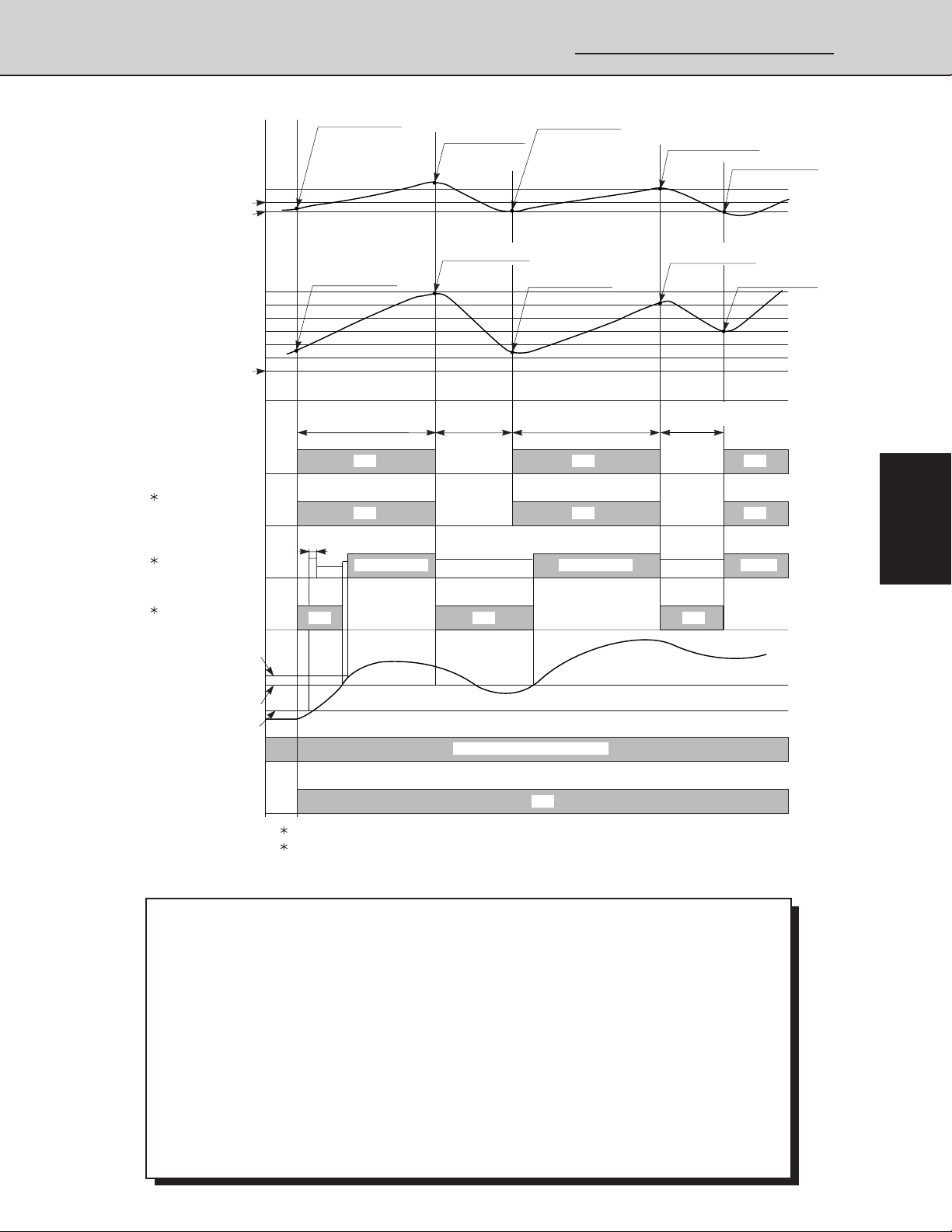
2. Processes and functions
1. Specifications
(B) Heating
REMOTE CONTROL
SENSOR
(Only for wireless
remote controller)
SETTING TEMP.
BODY SENSOR
SET TEMP.+7°F SHIFT
COMPRESSOR
1
OUTDOOR FAN
(H OR M)
2
INDOOR FAN
SET. +2°F
SET. –2°F
+2°F
–2°F
SET TEMP.
OFF
THERMO. ON
THERMO. ON
ONOFF
3 SECONDS
LL
LL
THERMO. OFF
THERMO. OFF
3 MINUTES
OFF
LL
THERMO. ON
THERMO. OFF
THERMO. OFF
MORE THAN
5 MINUTES5 MINUTES
ON OFF ONOFFOFF ON
ON OFF ON
SET SPEEDSET SPEED
MORE THAN
3 MINUTES
LL
THERMO. ON
THERMO. ONTHERMO. ON
Section
1
2
SET SPEED
2
STANDBY
INDOOR HEAT
EXCH.
COIL
TEMP.
E2
SOLENOID
COIL (4-WAY)
TEMP.
OPERATION
BUTTON
(88°F)
81°F
77°F
OFF
ON ON ON
OFF
1. Refer to 2-4 Outdoor Fan Speed Control
2. Refer to 2-2 Cold Draft Prevention (Heating)
OFF OFF
ON (REVERSING CYCLE)
ON
Chart Summary and Explanations
❑ Once the compressor starts, it keeps running for 5 minutes.
❑ Once the compressor stops, it will not start running again for 3 minutes.
❑ If you change the operation mode (HEAT, COOL or FAN) during the heating cycle, the
control circuit stops the compressor for 3 minutes.
❑ For 5 minutes after the compressor is first turned on, and for 3 minutes after it is turned off,
the compressor is not controlled by the room sensor.
When set on remote control sensor
Thermo ON: When room temperature is –2°F below the set temperature T˚.
Compressor ➞ ON
Thermo OFF: When the room temperature is 2°F above the set temperature T˚, (T˚+2°F)
Compressor ➞ OFF
When set on body sensor
NOTE: In case of Body sensor, operating temperature is shifted to setting temperature +7°F.
OFF
3
4
1134_THS_I
Fig. 2
– 27 –
SM830076
Page 28
2. Processes and functions
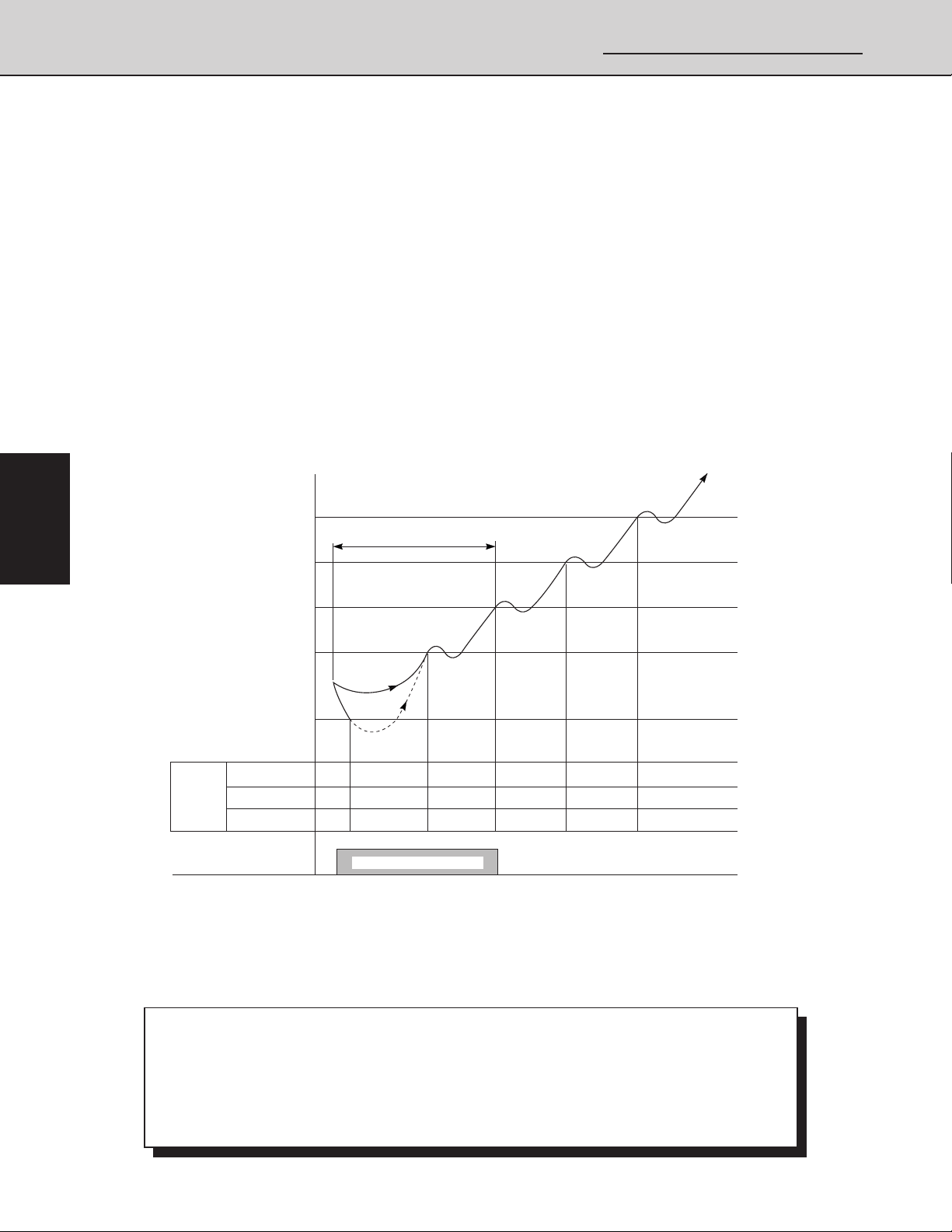
2-2 Cold Draft Prevention (Heating Cycle)
The cold draft prevention function controls indoor fan speed so a strong draft of cold air will
not blow out before the indoor heat exchange coils have warmed up.
❑ STANDBY shows on the remote controller when the indoor fan speed is LL (very
low) or OFF. This condition occurs in the following 3 cases:
• During Thermo OFF (refer to 2-1 B). Room Temperature Control, Heating)
Section
1
2
3
• During the defrosting operation (refer to 2-10 Defrosting Control, Heating)
• Until either the coil temperature E2 reaches 81°F or when a maximum of 6 minutes
has past.
❑ The indoor fan motor operates in L instead of LL for 3 seconds as it starts to give
the fan an initial boost.
92
MAX. 6 MINUTES
INDOOR UNIT
COIL TEMP.
E2 (°F)
88
81
77
50
4
SET
FAN
SPEED
❑ The main idea of this chart is to show that the indoor fan speed increases and gets closer to
❑ The indoor unit’s coil temperature is taken from sensor E2 located in the middle of the indoor
❑ The dotted line shows that the indoor fan motor is OFF. When the temperature at sensor E2
AUTO OR H
“STANDBY”
INDICATOR
the set fan speed as the coil temperature E2 rises.
heat exchange coil.
falls below 50°F, the indoor fan motor stops running.
LL LL/OFF LL L M H
M
LL LL/OFF LL L M M
L LL LL/OFF LL L L L
“STANDBY” APPEARS
LL= Very low speed
L= Low speed
Chart Summary and Explanations
– 28 –
M= Medium speed
H= High speed
1135_THS_I
Fig. 3
SM830076
Page 29
2. Processes and functions
1. Specifications
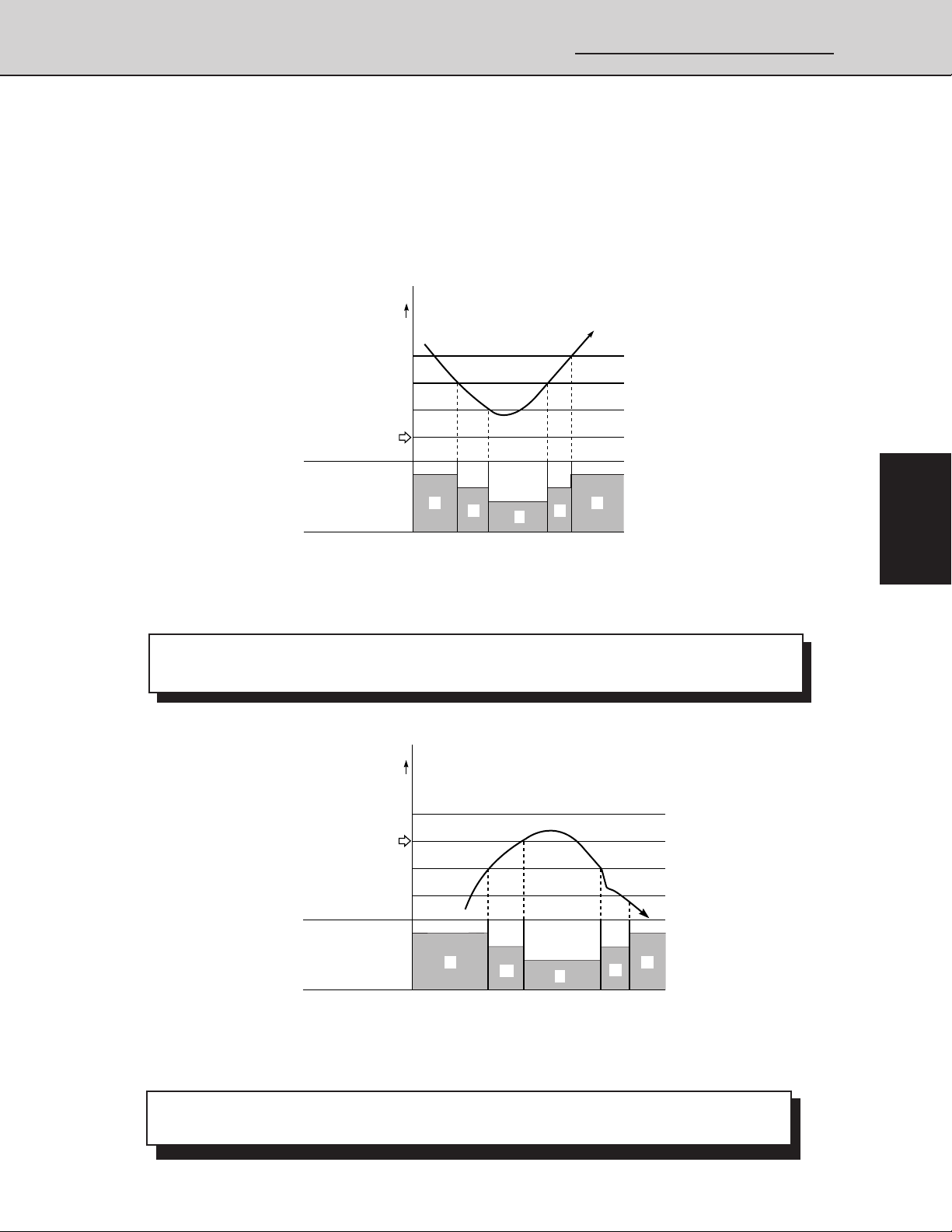
2-3 Automatic Fan Speed (Indoor Unit)
By pressing the FAN SPEED button on the remote controller, the fan speed can be set at
one of four steps: AUTO., HI., MED., or LO. When set at AUTO. the indoor unit fan speed
will be automatically adjusted to the room temperature as the two charts shown below.
(A) Cooling
❑ When the fan speed changes, it keeps the speed step for at least 3 minutes, even if the
(B) Heating
ROOM TEMP.
(deg)
+3
+2
+1
SET TEMP.
INDOOR FAN
SPEED
HM: High
: MiddleLLL
: Low
: Very low
H
MM
L
Chart Explanations and notes
temperature changes to another speed step during the time.
Section
1
H
2
0433_M_S
Fig. 4
3
ROOM TEMP.
(deg)
SET TEMP.
–2
–4
INDOOR FAN
SPEED H
HM: High
: MiddleLLL
: Low
: Very low
M
L
H
M
0434_M_S
Chart Explanations and notes
❑ When the fan speed changes, it keeps the speed step for at least 1 minute, even if the
temperature changes to another speed step during the time.
– 29 –
4
Fig. 5
SM830076
Page 30

2. Processes and functions
2-4 Outdoor Fan Speed Control
To optimize the performance of air conditioner, the outdoor fan speed is selected
automatically according to the outdoor temperature.
❑ Note that in both Cooling and Heating modes, the fan comes on at first at high
speed (H mode) for 5 seconds. Since outdoor conditions sometimes make it
difficult for the fan to start, this sudden surge of power may be necessary.
Section
1
2
3
❑ The outdoor fan operates in H mode for 3 minutes after the compressor stops
(excluding defrosting operation period).
❑ Charts below show how the outdoor fan speed changes with the change in
outdoor temperature.
(A) Cooling
Outdoor unit coil Outdoor fan
temperature [C2] motor (FMo)
or more 77°F H
less than 77°F M
77
OUTDOOR TEMPERATURE (°F)
H
M
Fig. 6
4
(B) Heating
Outdoor coil Outdoor fan
temperature [C2] motor (FMo)
or more 57°F M
less than 57°F H
M
57
H
OUTDOOR TEMPERATURE (°F)
Fig. 7
SM830076
– 30 –
Page 31

2. Processes and functions
1. Specifications
2-5 Freeze Prevention (Cooling)
Freeze Prevention keeps the indoor heat exchange coil from freezing. Freezing reduces the
efficiency of the unit, and frost buildup on the coil blocks cool air circulation from the indoor
unit's fan.
MIN. VALUE OF
EITHER E1 OR E2
INDOOR UNIT
TEMP.
ELECTRONIC REF.
CONTROL
VALVE SIGNAL
COMPRESSOR
(°F)
34
32
31
30
OPEN
CONTINUOUS
DETECTION
FOR 2 MINUTES
OPEN
ON ON
MINIMUM 3
MINUTES
Fig. 8
1138_THS_I
Note: Freeze prevention is controlled by the temperature at the indoor heat
exchanger coil as sensed by either sensor E1 (located at the entrance
of the coil) or sensor E2 (located on the middle of the coil). Freeze
prevention cycle is controlled by the lower temperature sensed at either
of the two sensors.
Chart Explanations and notes
Section
1
2
3
4
❑ This chart shows when the electronic refrigerant control valve opens to regulate the
temperature of the indoor unit coil to prevent freezing.
❑ If the refrigerant control is not effective and the temperature continues to drop and stays
below 30°F for 2 minutes continuously, the control circuit stops the compressor. The
compressor does not start again until the temperature rises above 34°F.
The compressor stops for 3 minutes minimum.
– 31 –
SM830076
Page 32

Section
I
1
2. Processes and functions
2-6 Condensing Temperature Control (Cooling)
Condensing temperature is controlled by the outdoor heat exchanger coil temperature as
sensed by sensor C2.
140
OUTDOOR UNIT
COIL TEMP. C2
(°F)
131
2
3
4
OUTDOOR FAN
SPEED
ELECTRONIC REF.
CONTROL VALVE
❑ This chart shows how the outdoor fan speed and the electronic refrigerant control valve
react to coil temperature to control condensing temperature.
❑ Sensor C2 is located in the middle of the outdoor unit heat exchange coil.
❑ When C2 rises above 140°F the electronic refrigerant control valve opens at 50 steps/30
seconds, and the outdoor fan speed is forced to change to high (H) until C2 falls below
131°F.
H, M H, M
Chart Explanations and notes
FORCED
H
OPEN
1139_THS_
Fig. 9
– 32 –
SM830076
Page 33

2-7 Overload Protection (Heating)
This function prevents the air conditioner from overloading.
(°F)
147
144
2. Processes and functions
1. Specifications
INDOOR UNIT COIL
TEMP. (E2)
ELECTRONIC REF.
CONTROL VALVE
OUTDOOR FM
140
138
131
127
OVERLOAD
PROTECTION OVERLOAD PROTECTION
OPEN
H OR M H OR MH M
OPEN
START UP
COMPENSATION
OFF
FUZZY CONTROLFUZZY CONTROL
Chart Explanations and notes
❑ This chart shows how the outdoor fan speed and the electronic refrigerant control valve
react to coil temperature to keep the indoor heat exchanger coil from overloading.
❑ When sensor E2 rises above 140°F the electronic refrigerant control valve opens at 50
steps/30 seconds until E2 falls below 138°F.
❑ Sensor E2 is located in the middle of the indoor unit heat exchange unit.
❑ When sensor E2 rises above 144°F, the control circuit stops the outdoor fan motor till the
temp. drops to 131°F
❑ Fuzzy control controls the electronic refrigerant control valve.
Fig. 10
Section
1
2
1140_THS_I
3
4
– 33 –
SM830076
Page 34

2. Processes and functions
2-8 Discharge Temperature Control (Cooling and Heating)
This function prevents the compressor motor from burnout by overheating.
239
221
203
Section
1
2
3
4
200
DISCHARGE GAS
TEMP. (°F)
OUTDOOR
FAN SPEED
COMPRESSOR
ELECTRONIC REF.
CONTROL VALVE
(DISCHARGE TEMP.)
194
185
H OR M
M
ON
H OR M
OPENOPEN
TRIP IS OPERATED.
Chart Summary and Explanations
❑ Discharge temperature is sensed by TH8 (discharge gas sensor).
❑ When the temperature rises above 203°F the electronic refrigerant control valve opens at
50 steps/30 seconds until the temperature falls below 200°F.
❑ During HEATING operation, when the temperature rises above 221°F, the control circuit
stops the outdoor fan motor until the temperature falls below 194°F. Please note that this
control does not function during COOLING operation.
❑ For both COOLING and HEATING modes, if the temperature reaches 239°F the operation
shuts down and alarm P3 appears on the remote controller.
❑ The outdoor fan speed is controlled on discharge temp. at heating mode.
1141_THS_I
Fig. 11
– 34 –
SM830076
Page 35

2. Processes and functions
1. Specifications
2-9 Auto. Mode for Automatic Heating/Cooling Switching
❑ When the AUTO mode is selected, the microprocessor calculates the difference
between the set temperature and the room temperature, and automatically switches
to the COOLING or HEATING mode to maintain the desired temperature.
Room temp. ] Set temp. ➔ COOLING
Room temp. < Set temp. ➔ HEATING
This means that if the room temperature is higher or equal to the set temperature,
COOLING operation starts. If the room temperature is lower than the set
temperature, HEATING operation starts.
A
COOLING SELECTION TEMP.
SHIFT SET TEMP.
+5 deg
+4 deg
Section
1
REMOTE CONTROLLED
SET TEMP.
SHIFT SET TEMP.
–4 deg
HEATING SELECTION TEMP.
–6 deg
B
C
HEATING COOLING HEATING
2
3
1142_THS_I
Fig. 12
4
– 35 –
SM830076
Page 36

Section
1
2
2. Processes and functions
Chart summary and Explanations
❑ This chart shows how the Operation Mode (COOLING or HEATING) is determined by the
microprocessor taking the room temperature into consideration. It also shows the
temperature points at which the cooling or heating mode is switched, when the AUTO mode
is selected.
❑ After operation starts, the set temperature shifts automatically by +4 deg. at cooling and
by -4 deg. at heating. For example, if cooling is selected, the set temperature changes from
68°F to 72°F.
(The display of the remote controller remains 68°F.)
❑ The change of the operation mode (heating to cooling, cooling to heating) by the change of
the room temperature during the operation is as follows.
Heating to Cooling; Room temp. ≥ Shifted temp +1.0 deg.
Cooling to Heating; Room temp. ≤ Shifted temp -2.0deg.
For example, if the room temperature rises above 73°F (=72+1) during the cooling
operation at the room temperature 68°F set by the remote controller, the operation changes
to cooling. When the room temperature lowers below 63°F (=65-2) thereafter, the operation
changes to heating again.
❑ In heating operation, using the body sensor, room temperature control is designed so that
room air temp. is sensed as 8 deg. lower than suctioned air at indoor unit taking into
account of the temperature gap between upper part and lower part of the room.
❑ Within 10 minutes after the compressor turns OFF, the operation does not change to
cooling (heating), even when the room temperature changes from C to A (A to C).
❑ When switching from cooling (heating) to heating (cooling), the actuation of the 4 way valve
will delay about 30-50 seconds after the compressor turns ON.
3
4
– 36 –
SM830076
Page 37

2. Processes and functions
1. Specifications
2-10 Defrosting Control, Outdoor Heat Exchanger Coil (Heating)
When the outdoor temperature is low, frost may form on the outdoor heat exchanger coil.
When this occurred, the defrosting system operates. The microprocessor in the outdoor unit
monitors the relationship between the temperature of the outdoor heat exchanger coil and the
outdoor temperature so it can defrost when necessary.
Flow of Defrosting
Heating operation
No counting time for detecting
frost : 15 minutes
Detecting the frost
Stand by time for defros:
25 minutes
Defrosting
Release of defrosting
Time Chart for Defrosting
OUTDOOR COIL
TEMP. C1 (°F)
Y
“RELEASE OF
DEFROSTING”
RANGE
50
OUTDOOR AIR TEMP.
7.3 50
27
18
The area below the heavy line
is the frost detection area.
–4
Either continuous 8 minutes or cumulative 60 minutes
are required to detect frost in the “Frosting” range.
Refer to time chart.
*Minimum continuous operating time by defrosting is 48 minutes (= 15 + 8 + 25).
Occurs either when the temperature of C1 (the outdoor
heat exchanger coil) has reached 50°F or above,
or when the maximum defrosting time (9 minutes)
has elapsed.
MAX. 9 MINUTES 1 MINUTE1 MINUTE
(°F)
X
Section
1
2
3
1143_THS_I
Fig. 13
COMPRESSOR
SOLENOID COIL
(4 WAY VALVE)
OUTDOOR FAN
(H OR L)
INDOOR FAN
(SET SPEED)
“STANDBY”
INDICATOR
❑ During the defrost cycle, STANDBY appears on the remote controller.
❑ *......Cold Draft Prevention may operate occasionally
ON
ON
ON
“STANDBY” APPEARS
Defrosting
Start
ON ON
OFF OR LL
Release of
Defrosting
– 37 –
OFF
OR LL
ON
ON
0442_M_S
4
Fig. 14
SM830076
Page 38

Section
1
2. Processes and functions
2-11 4-Way Valve, Solenoid Control
The basic function of the 4-way valve is to direct the refrigerant in the correct direction
according to the Operation Mode (COOLING or HEATING) selected.
The following two charts show conditions of the controls and functions listed in the left hand
column when the solenoid is ON or OFF. Chart (A) on this page shows the relationships when
the temperature control is in NORMAL mode, and Chart (B) on the next page shows the
relationships when the remote controller is set to AUTO mode.
(A) Normal Control Mode
2
3
4
POWER SOURCE
OPERATION
BUTTON
MODE
BUTTON
COMPRESSOR
SOLENOID COIL
(4-WAY VALVE)
COOL
HEAT
OFF
OFF
HEAT
2
3 MINUTES
TURN OFF
ON ON ON
OFF
1. . . More than 5 minutes 2. . . More than 3 minutes
ON
TURN ON
ON
COOL
THERMO OFF
OFF
ONON
THERMO
ON
1 111
HEAT
THERMO OFF
OFFOFFOFF
22
ON
THERMO
ON
ON
0443_M_S
Fig. 15
Chart Summary and Explanations
❑ For the first 3 minutes after power is applied, the 4–way valve remains OFF and the
compressor will not operate, even if the ON button is pushed.
❑ If the 4–way valve is turned OFF with the compressor operating, the air conditioner
operates in COOLING mode. See Table below.
❑ If the 4–way valve is turned ON with the compressor operating, the air conditioner operates
in HEATING mode. See Table below.
Operation Mode
COOLING OFF
HEATING ON
4-way valve
solenoid
Compressor
ON
– 38 –
SM830076
Page 39

(B) AUTO Control Mode
2. Processes and functions
1. Specifications
ON
ON
MORE THAN 10 MINUTES
(THERMO. OFF)
COOL
OFFOFF
MORE THAN
30 – 50 SECONDS
OFF
HEAT
THERMO. OFF
THERMO. ON
MORE THAN
3 MINUTES
ON
0445_M_S
OPERATION
BUTTON
AUTO
MODE
CONTROL HEAT
COMPRESSOR
SOLENOID COIL
(4-WAY VALVE)
COOL
OFFPOWER SOURCE
MORE THAN 10 MINUTES
3 MINUTES
OFF OFF
OFF
ON ON ON ON
30 – 50 SECONDS
(THERMO. OFF)
HEAT
MORE THAN
ON
Fig. 16
When the Compressor has stopped while in AUTO mode, the 4-way valve switches on
(heating) or off (cooling) within 1 minute according to the following conditions:
Section
1
2
3
Compressor has stopped
under the operation of
“AUTO mode” condition.
4-way valve delays its
switching for 30 – 50 seconds
after compressor has been
turned ON.
0446_M_S
2-12 Automatic Restart after Power Interruption
This air conditionner has a power failure recovery function.
4
Fig. 17
– 39 –
SM830076
Page 40

2-13 Electronic Expansion Valve
❑ This valve allows very precise and smooth control of the amount of refrigerant flow in the
system. Since the valve is operated by a step motor, the control circuits can open or
close it in very exact amounts, so the degree of heating or cooling can be changed by
just a little, or changed very quickly or slowly.
(Completely close …… 0 step)
(Full open ................480 step)
2. Processes and functions
Section
1
2
3
4
Model
24 type 100 step 120 step 480 step
36 type 90 step 90 step 480 step
Heating Cooling
Min. open
Max. open
❑ Fuzzy Control
Fuzzy Control is a controlling system to control electronic refrigerant control valve using
fuzzy logic. It regulates the functions of heating and cooling, as well as some of the
processes inside the unit, by taking account of many different conditions of temperature,
fan speed, etc. These control circuits work automatically to send just the right amount of
refrigerant through the Electronic Refrigerant Control Valve.
2-14 Compressor Discharge Gas Temperature
(A) Cooling
Indoor temp. (°F) 68 – 77 79 – 82 84 – 90
Outdoor temp. (°F) 55 or below 57 – 61 81 – 95 97 – 109
Compressor discharge
gas temp. (°F)
104 – 176 104 – 194 140 – 212 158 – 221
(B) Heating (Except During Defrosting)
Indoor temp. (°F) 64 – 70 72 – 77 79 – 86
Outdoor temp. (°F)
Compressor discharge
gas temp. (°F)
❑ Operate the unit at least 30 minutes to stabilize the discharge temperature.
❑ The above discharge temperature was measured with a 15m tubing length.
The temperature may vary with tubing length.
32 or below
104 – 176122 – 194122 – 194122 – 212140 – 221 122 – 194 140 – 212 158 – 221
34 – 50
32 or below
– 40 –
34 – 50 52 – 70
32 or below
34 – 50 52 – 70
SM830076
Page 41

2. Processes and functions
1. Specifications
2-15 Compressor Current Detection Circuit
❑ The Compressor Current Detection Circuit detects the compressor current and,
depending on the current range, can stop the compressor motor so it will not be
damaged by overcurrent.
❑ Overcurrent can be caused by several factors, particularly mechanical seizing of the
compressor or liquid backflow. Either of these conditions can hold the compressor
to run, and thus drawing so much current that the motor can burn out.
Comp. Amps.(A)
Locked Comp. Cut-off Range
Is 1.4
+
Is 1.17
+
Is
Rated Current
value
Overload Protection Range
Normal Operation Range
0447_M_S
Section
1
Fig. 18
Outdoor Model
CH2432 17.1 20.0 23.9
CH3632 27.5 32.0 38.5
❑ Overload Protection
• When the detected current is 1.17 – 1.4 times greater than the rated current value (Is) and continues
for 30 seconds, both compressor and outdoor fan stop (Thermostat OFF).
• After 3-minute pause, if the air conditioner is ready for Thermostat ON, it starts again. However, if the
condition mentioned above repeats twice within 30 minutes, the remote controller displays the alarm
message H01, compressor overload.
❑ Locked Compressor Cut-off
• When the detected current is 1.4 times greater than the rated current value (ls) and continues for 2
seconds, both compressor and outdoor fan stop (Thermostat OFF).
• After 3-minute pause, if the air conditioner is ready for Thermostat ON, it starts again. However, if the
condition mentioned above repeats twice, the remote controller displays the alarm message H02,
compressor locked.
❑ Failure of Compressor Current Detection
• When the Compressor Current Detection Circuit fails to detect the compressor current within 2
seconds after compressor starts, both compressor and outdoor fan stop (Thermostat OFF).
• After 3-minute pause, if the air conditioner is ready for Thermostat ON, it starts again. However, when
the circuit fails to detect the current twice in a row, the remote controller displays alarm message H03,
Failure of compressor Current Detection.
Rated Current Value Overload Protection Locked Compressor Cut-off
ls (A) ls x 1.17 (A) Is x 1.4 (A)
Chart Summary and Explanations
2
3
4
– 41 –
SM830076
Page 42

2. Processes and functions
2-16 Electronic Expansion Valve Control
The circulation volume of the refrigerant is controlled by a pulse type electronic control valve.
When the power is switched ON, the opening degree of the electronic control valve is
controlled between 90 and 480 steps after setting the initial step at the time when the
thermostat is ON.
Contents and Order of control
Section
1
2
3
4
Cooling
Start
Discharge gas temperature control
Outdoor unit coil temperature control
Freeze prevention control
Refrigerant flow distribution control
Discharge gas target temperature
control (Fuzzy control)
*
Repeat control in accordance with the priority order.
*
Discharge gas temperature control
High load prevention control
Refrigerant flow distribution control
Discharge gas target temperature
control (Fuzzy control)
Heating
Start
Heating start up control
*
0451_M_S
Even though the operation is performed every 30 seconds, the control of discharge gas
temperature, high load prevention, outdoor unit coil temperature and freeze prevention
activates when it occurs.
(1) Refrigerant flow distribution control
At the control of flexible combination (a plural number of indoor units are set), the opening
degree of the electronic control valve is controlled by the indoor unit coil temperature.
Cooling: indoor unit coil E2 temperature (located at the middle of coil)
Heating: indoor unit coil E1 temperature (located at the outlet of coil)
(2) Fuzzy control (optimal refrigerant flow rate control)
By outputting the fuzzy estimation result corresponding to the fuzzy input variables (the indoor
unit coil temp., the deviation between the actual discharge gas temp. and the target discharge
gas temperature calculated from the outdoor unit coil temperature and the change thereof),
the electronic refrigerant valve is controlled so that the unit can perform its maximum ability in
accordance with the indoor and outdoor temperature conditions at the operation.
– 42 –
SM830076
Page 43

2. Processes and functions
2-17 Voltage Detection Control
When the power voltage falls below 160 V or rises above 260 V, operation lamp and stand-by
lamp flash alternately to protect the compressor and electrical components.
1. Specifications
Section
1
2
3
4
– 43 –
SM830076
Page 44

Section
1
2. Processes and functions
2
3
4
– 44 –
SM830076
Page 45

3. Electrical data
3. ELECTRICAL DATA
3-1 Indoor Unit (Electric Wiring Diagram, Schematic Diagram) ............................... 46
3-2 Outdoor Unit (Electric Wiring Diagram, Schematic Diagram)............................. 48
Section
1
2
3
4
– 45 –
SM830076
Page 46

3-1 Indoor Unit
11
1 XHS2432, XHS3632
11
3. Electrical data
Section
1
2
3
4
ORG
Connector
GRN/YEL
BLK
LM
Earth
Terminal
49FI
GRN/YEL
FMI
RC1
Earth
• Electric Wiring Diagram
Control
Line
Terminal
GRY
IND
GRY
GRY
WHT
VLT
ORG
YEL
BLK
BRN
PNK
G
2 U1 U2
Power
Line
To Outdoor Unit
1
3P(WHT)
123
123
P
S
61
61
Connector
S
P
Connector
9P(WHT)
23456789
123456789
1
S
P
PNK
BRN
BRN
6P(WHT)
CONT
GRN/YEL
BLK
GRY
RED
BRN
VLT
ORG
YEL
BLK
BLU
PNK
WHT
RED
Earth
Terminal
BLK
WHT
RED
YEL
PNL
(GRN)
212121
(BLK)
Coil E2
(GRN)
(RED)
Coil E1
GLM
12VSGCD
2143
31 31
49FI(GRY)
HH
5713 231231
31
COM(YEL) HLLL
SG 12V G
21
SG1 SG2
31
N
R
(YEL)
WL(BLU)
FMI(WHT)
RC(BLU)
SG1(BLU)
SUP(BLK)
Room Temp
43
21
SEC(WHT)
31
N
Controller (CR-THS2432)
R
PRY(WHT)
453
21
T6 (WHT)DP (BLU)FS (RED)E
31
31
BLK
BLK
BLK
BLK
BLK
BLK
BRN
BRN
RED
RED
WHT
WHT
GRY
BLK
YEL
RED
ORG
BLK
BLK
BLK
BLK
DP
GRN/YEL
TR1
MOV
FS
Earth
TH1 TH2 TH3
GRN/YEL
Terminal
Earth
Terminal
W 854-2-5268-772-00-0 (XHS)
Terminal
Plate(4P)
– 46 –
SM830076
Page 47

3-1 Indoor Unit
11
1 XHS2432, XHS3632
11
4P-1
4P-2
N COM
F1(3A)
1
R
1X
3X 3X
LL L HHH COM
LL L HHHHT
FMI
RC1
F2(3A)
3. Electrical data
• Schematic Diagram
CR-THS2432
Controller
CD
CONT
3X
RY2
2X
RY1
49FI
1
SG WL
2
12V
3
G
4
1
2
SEC
3
4
1
PRY
3
3
1X
LM
DP
DC12V
SG1
12VRC
PNL
SG1
SG2
SG
T6
FS
G
1
2
3
1
2
3
4
5
1
2
3
1
3
Room Thermistor
1
2
Indoor Coil
1
2
Indoor Coil
1
2
1
2
4P-U24P-
To Outdoor Unit
MOV
U1
TH1
E1
TH2
E2
TH3
Section
1
FS
2
3
49FI
1
2X
21
RY2
DP
11357
6 7543
8
49FI
9
RY1
LM
1
DP
333
1
1
LM
2
3
1
IND
6
TR1
Symbols Description
FMI
49FI
RC1
F1,2
DP
LM
TR1
1X-3X
RY1-RY2
MOV
FS
Indoor Fan Motor
Indoor Motor Thermal Protector
Running Capacitor
Fuse
Drain Pump
Auto Louver Motor
Power Transformer
Auxiliary Relay
Auxiliary Relay
Motor Operated Valve
Float Switch
Symbols Description
TH1
TH2
TH3
CR-THS2432
CONT
IND
Room Thermistor
Thermistor (Indoor Coil E1)
Thermistor (Indoor Coil E2)
Indoor Controller
Controller
Indicator Lamp Assy
Terminal Plate
Connector
Terminal
S 854-2-5268-772-00-0 (XHS)
4
– 47 –
SM830076
Page 48

Section
1
3-2 Outdoor Unit
11
1 CH2432
11
TH6
BLK
1
C1
BLK
2
(BLK)
TH7
BLK
1
C2
BLK
2
(RED)
TH8
WHT
WHT
2
1
Discharge
Gas (GRN)
21
SEC
2P
(WHT)
13
PRY
3P(WHT)
31
63PH
3P(RED)
31
20S
3P(YEL)
BRN
BRN
WHT
WHT
GRY
RED
BLK
BLK
TR
AC 14V
AC 208V
AC 230V
RED
3. Electrical data
63PH
S
P
BLK
21
21
BLK
20S
W 854-2-5268-582-00-2 (CH2432)
2
3
4
SUP
3
BRN
3P (BLU)
1
GRN/YEL
9P(WHT)
3P(BLK)
3P(WHT)
RED
CN24
31 35791
52C
31
CT1
E
GRN/YEL
Earth Terminal
BLK
BLK
BRN
ORG
GRY
BRN
BRN
RED
WHT
Controller (CR-CH2432)
CN2
2P (BLU)
2
1
BLU
• Electric Wiring Diagram
PNK
1 2
U1 U2
To Indoor Unit
Terminal
Plate (2P)
RC2
7
6
5
Connector
2P (BLK)
P
87
VLT
65
WHT
BLK
43
GRY
BRN
21
PNK
Connector
24
13
8
1Y
Relay
Connector
BRN
21
YEL
P
S7
8
65
43
21
8P (WHT)
2P (WHT)
21
S
Earth
YEL
VLT
WHT
GRY
GRY
BRN
PNK
WHT
WHT
Terminal
GRN/YEL
49FO
FMO
CH
Earth
L2 GL1
To Indoor Unit Power Supply
Terminal
Terminal Plate (5P)
WHT
12G L1 L2
RED
RED
WHT
RED
BLK
BLK
PTC
RC1
WHT
WHT
BLK
RED
S
R
CM
C
32
UVW
RST 31
A
B
CT
52C
SM830076
– 48 –
Page 49

3-2 Outdoor Unit
11
1 CH2432
11
3. Electrical data
Terminal
Plate (5P)
-1
-2
-G
-L1
-L2
CT
52C
R
CS
CM
RC1
PTC
63PH
1
F1(3A)
52C
1
CH
2
3
F2(3A)
Symbols Description
CM
FMO
52C
49FO
63PH
CT
RC1, RC2
TR
CH
20S
F1, F2
Compressor Motor
Outdoor Fan Motor
Compressor Motor Magnetic Contactor
Outdoor Fan Motor Thermal Protector
High Pressure Switch
Current Transmitter
Running Capacitor
Power Transformer
Crank Case Heater
Four Way Valve
Fuse
• Schematic Diagram
63PH
1
RY2
3
7
49
FO
3
4
9
49
C
Symbols Description
TH6
TH7
TH8
PTC
CR-CH2432
RY1~RY4
1Y
RY3
RY4
H LL 20S 52C
HLM
1Y
FMO
RC2
RY1
53
3 3
2
765
20S
52C
21
1
1
1
1
CR-CH2432
Controller
Discharge
N1
CN2
PRY
SEC
Outdoor
Coil C1
Outdoor
Coil C2
Gas
CT1
1Y
49FO
RY1
RY2
RY3
RY4
20S
52C
FM1
FM2
DC12V
Thermistor (Outdoor Coil C1)
Thermistor (Outdoor Coil C2)
Thermistor (Discharge Gas)
PTC Thermistor
Outdoor Controller
Auxiliary Relay
Auxiliary Relay
Terminal Plate
Terminal
Connector
S 854-2-5268-582-00-2 (CH2432)
1
2
1
3
2
1
1
2
1
2
1
2
1
3
(U1) (U2)
AC 208V
230V
AC 14V
2P-22P-1
Section
TR
1
TH6
TH7
TH8
2
3
4
– 49 –
SM830076
Page 50

Section
1
3-2 Outdoor Unit
22
2 CH3632
22
TH6
BLK
1
C1
BLK
2
(BLK)
TH7
BLK
1
C2
TH8
BLK
2
(RED)
WHT
WHT
2
1
Discharge
Gas (GRN)
21
SEC
2P
(WHT)
13
PRY
3P(WHT)
31
63PH
3P(RED)
31
20S
3P(YEL)
BRN
BRN
WHT
WHT
GRY
RED
BLK
BLK
TR
AC 14V
AC 208V
AC 230V
RED
3. Electrical data
24
6
13
5
7
8
1Y
WHT BLK
Connector
2P (WHT)
S
RED
P
21
21
S
P
21
21
WHT
RED
BLK
BLK
63PH
20S
W 854-2-5268-621-00-0 (CH3632)
2
3
4
VLT
WHT
SUP
3
BRN
3P (BLU)
1
RED
CN24
35791
9P(WHT)
31
52C
3P(BLK)
E
CT1
3P (WHT)
3
1
BLK
BLK
GRN/YELGRN/YEL
Earth Terminal
BRN
ORG
BRN
BRN BRN
BRN
GRY
Controller (CR-CH2432)
CN2
2P (BLU)
2
1
BLU
• Electric Wiring Diagram
PNK
1 2
U1 U2
To Indoor Unit
Terminal
Plate (2P)
RC3
RC2
Connector
2P (BLK)
P
87
VLT
65
WHT
GRY
43
BRN
21
PNK
Connector
P
87
VLT
65
WHT
GRY
43
GRY
BRN
21
PNK
Connector
Connector
BRN
21
YEL
P
S7
8
65
43
21
8P (WHT)
S7
8
65
43
21
8P (WHT)
2P (WHT)
21
S
YEL
VLT
WHT
GRY
GRY
BRN
PNK
Earth
YEL
VLT
WHT
GRY
GRY
BRN
PNK
WHT
WHT
Terminal
CH
FMO2
GRN/YEL GRN/YEL
49FO1 49FO2
FMO1
Earth
L2 GL1
To Indoor Unit Power Supply
Terminal
Terminal Plate (5P)
WHT
12G L1 L2
RED
WHT
RED
BLK
BLK
PTC
RC1
WHT
WHT
BLK
RED
S
R
CM
C
32
UVW
RST 31
A
CT
RED
52C
B
SM830076
– 50 –
Page 51

3-2 Outdoor Unit
22
2 CH3632
22
3. Electrical data
Terminal
Plate (5P)
-1
-2
-G
-L1
-L2
CT
52C
CS
R
CM
RC1
1
2
PTC
63PH
1
F1(3A)
52C
1
CH
1Y
2
RC2
3
F2(3A)
Symbols Description
CM
FMO1, 2
52C
49FO1, 2
63PH
CT
RC1, 2, 3
TR
CH
20S
F1, F2
Compressor Motor
Outdoor Fan Motor
Compressor Motor Magnetic Contactor
Outdoor Fan Motor Thermal Protector
High Pressure Switch
Current Transmitter
Running Capacitor
Power Transformer
Crank Case Heater
Four Way Valve
Fuse
• Schematic Diagram
63PH
RY1
3 3
2
1
1
RY2
49
FO
52C20S
49
C
1
Symbols Description
TH6
TH7
TH8
PTC
CR-CH2432
RY1~RY4
1Y
HLM
FMO1
RY3
RY4
H LL 20S 52C
53
HLM
765
765
FMO2
21
21
RC3
1
CR-CH2432
20S
52C
FM1
FM2
DC12V
Controller
Discharge
N1
CN2
PRY
SEC
Outdoor
Coil C1
Outdoor
Coil C2
Gas
CT1
1
1Y
1Y
3
7
3
49FO1
4
3
49FO2
4
9
RY1
RY2
RY3
RY4
Thermistor (Outdoor Coil C1)
1
2
1
3
2
1
1
2
1
2
1
2
1
3
(U1) (U2)
AC 208V
230V
AC 14V
2P-22P-1
Section
TR
1
TH6
TH7
TH8
2
3
Thermistor (Outdoor Coil C2)
Thermistor (Discharge Gas)
PTC Thermistor
Outdoor Controller
Auxiliary Relay
Auxiliary Relay
Terminal Plate
4
Terminal
Connector
S 854-2-5268-621-00-0 (CH3632)
– 51 –
SM830076
Page 52

Section
1
3. Electrical data
2
3
4
– 52 –
SM830076
Page 53

4. Service procedures
4. SERVICE PROCEDURES
4-1 Troubleshooting .............................................................................................54
(1) Check before and after Troubleshooting ................................................ 55
(2) General Troubleshooting Flow Chart: Diagnosis and Remedy .............. 56
(3) Meanings of alarm messages ................................................................ 58
(4) LED Indication on the Outdoor Unit’s P.C.B. Ass’y ................................ 60
(5) Symptoms and parts to inspect .............................................................. 61
(6) Procedures When a Specific Component Does Not Work ..................... 71
(7) Service Functions of Optional Wired Remote Controller........................ 73
Section
4-2 Checking the Electrical Components ............................................................ 87
(1) Measurement of Insulation Resistance .................................................. 87
(2) Checking the Protective Devices............................................................ 88
(3) Checking the Electrical Parts ................................................................. 89
(4) Sensor and Solenoid Layout Diagram.................................................... 92
(5) Thermistor Characteristic Curve............................................................. 94
(6) P.C.B. Setting..........................................................................................95
(7) R.C Address Setting Method.................................................................. 96
(8) Automatic Address Setting Method ........................................................ 97
(9) Displaying Indoor / Outdoor Unit Combination Numbers ....................... 97
(10) Items to Check Prior to Test Run ........................................................... 98
(11) Test Run..................................................................................................99
(12) P.C.B. and Parts Location.................................................................... 102
(13) Checking procedure for each PC Board............................................... 104
(14) Check Pins ............................................................................................105
1
2
3
4
– 53 –
SM830076
Page 54

Section
1
2
3
4
4. Service procedures
4-1 Troubleshooting
This section explains:
❑ What the LED codes mean
❑ What the remote control unit display screen messages mean
❑ How to use the flow charts to find and solve problems
How to use the self-diagnostic tests to find parts that aren’t working right
❑
This unit is made to be trouble free, and not need much service. However, with time, moving
parts wear out, electronic components break down, and sometimes misuse damages the unit.
The purpose of this section is to help you when the unit is not working properly. Sometimes
your experience will tell you right away where to look for a problem, and when you find it you
will know how to fix it at once.
Often, however, all you have is a symptom like “poor cooling” or “outside fan doesn’t come
on.” Now you must find out the cause of the problem, and then how to fix it. This section
provides several ways to help you go from the symptom to the cause and then the solution.
The first chart, General Troubleshooting Flow Chart is divided into two sections: Poor
heating and Poor Cooling. Under each heading you will find the main things that can go
wrong and cause either of these problems. Sometimes you can start with this chart and find
the problem right away, but often you will come here for more suggestions after you have
looked at the error code on the remote control unit display. This chart gives you the "big
picture" of problems and solutions.
The other main tool we explain here is the use of the Alarm Messages. When a certain part
fails or a safety device has shut the unit down, any alpha-numeric codes appears on the
display to guide you to the problem.
By understanding the code you can often go right to the problem area and then, with this
manual and your knowledge of air conditioning, find the solution.
– 54 –
SM830076
Page 55

4. Service procedures
(1) Check before and after Troubleshooting
Many problems may happen because of wiring or power supply problems, so you should
check these areas first. Problems here can cause false results in some of the other tests, and
so should be corrected first.
11
1. Check power supply wiring
11
❑ Check the power supply wires are correctly connected between terminal
No. 1 & 2 on the 5P terminal plates in the indoor unit and the outdoor unit.
22
2. Check inter-unit wiring
22
❑ Check that inter-unit control wiring (DC low voltage) is correctly connected between the
indoor unit and outdoor unit.
Power Supply: 60 Hz, single-phase, 230/208 V
Section
1
33
3. Check power supply
33
❑ Check that voltage is within the specified range (±10% of the rating).
❑ Check that power is being supplied.
Disconnect SW
(Field supply)
1
2
G
Ground
U1
C
U2
Inter unit
Indoor
control line
Unit
DC 5 V
Inter unit
power line
230/208 V
B
U1
U2
Outdoor
Unit
1
2
Power supply
single phase
G
230/208 V
L1
L2
G
A
Ground
L1
L2
1103_M_I
2
3
Fig. 19
4
If the following troubleshooting must be done with power being supplied, be
careful not to touch any uninsulated live part that can cause ELECTRIC
SHOCK.
44
4. Check the lead wires and connectors in indoor and outdoor units.
44
❑ Check that the sheath of lead wires is not damaged.
❑ Check that the lead wires are firmly connected at the terminal plate.
❑ Check that the wiring is correct.
– 55 –
SM830076
Page 56

Section
1
4. Service procedures
(2) General Troubleshooting Flow Chart: Diagnosis and Remedy
When you have found a major problem, such as refrigerant not flowing in the system or
reduced air circulation, come to this section and find the box listing the problem. Connected
to the box are the main causes of the problem and their remedies. To find out which
malfunction is happening in your case, check the remote controller for an Alarm Message,
and follow the steps in section 3).
(A) Cooling
a. Cooling
Poor cooling
Is setting temp.
suitable ?
Change the setting temp.
2
3
4
Refrigerant flow
failure
Is cooling load
too heavy ?
4-way valve is
defective.
Refrigerant
shortage
Electronic refrigerant
control valve is defective.
Service valves are not
fully open.
Review cooling load
estimate.
Replace the 4-way valve.
Charge refrigerant gas.
Replace the valve.
Replace the compressor.Compressor is defective.
Open the valves fully.
Not enough air
circulation
Air filter
is clogged.
Is fan speed
set to LOW ?
Refrigerant tubes between
indoor and outdoor units
are not insulated.
– 56 –
Clean the filter.
Set the fan speed to
either MEDIUM or HIGH.
Insulate wide and narrow
tubes separately.
0458_M_I
SM830076
Page 57

(B) Heating
b. Heating
Poor heating
4. Service procedures
Refrigerant flow
failure
Is setting temp.
suitable ?
Is heating load
too large ?
4-way valve is
defective.
Refrigerant
shortage
Electronic refrigerant
control valve is defective.
Service valves are not
fully open.
Change the setting temp.
Review heating load
estimate.
Replace the valve.
Charge with
refrigerant.
Replace the valve.
Replace the compressor.Compressor is defective.
Open the valves fully.
Section
1
2
3
Not enough
air circulation
Cold air is
discharged.
Cold draft prevention
is not working.
Air filter
is clogged.
Is fan speed
set to LOW ?
Refrigerant tubes between
indoor and outdoor units
are not insulated.
4-way valve is
defective.
“ STANDBY ” is
displayed.
Indoor coil sensor E2 is
defective.
Clean the filter.
Set the fan speed to
either MEDIUM or HIGH.
4
Insulate wide and narrow
tubes separately.
Replace the valve.
Replace indoor
P.C.B. Ass'y.
Replace the sensor.
0459_M_I
– 57 –
SM830076
Page 58

Section
1
2
3
4
4. Service procedures
(3) Meanings of alarm messages
If an error occurred in the air conditioner, the error condition is presented by indicating the
error code in the wired remote controller display or by the combination of lamp statuses for
operation, timer and heat stand-by (OFF status and flashing status).
Possible causes of troubles
Remote controller is detecting
unusual signal from indoor unit.
• Indoor unit is detecting unusual signal from the remote controller and group control.
(No serial communications signal)
Improper setting of indoor unit or
remote controller.
Indoor unit is detecting unusual
signal from signal option.
Improper setting of indoor unit or
remote controller.
Indoor unit is detecting
signal from outdoor unit.
Outdoor unit is detecting
unusual signal from indoor unit.
• Serial communication errors • Mis-setting• Mis-setting
Auto. address setting is not
correct.
Indoor unit is detecting unusual
signal from another indoor unit.
Improper setting of indoor unit or
remote controller.
Improper wiring connections of ceiling panel.
Protective device in indoor unit
is activated.
Protective device in outdoor unit
is activated.
• Activation of protective device
unusual
Error receiving of serial communications signal.
Error transmitting of serial communications signal.
Indoor unit address setting is duplicated.
Remote controller address (RCU.ADR) is duplicated.
Error transmitting of serial communications signal
Error receiving of serial communications signal.
When using flexible combination control, main indoor unit address
setting is duplicated. (judged by outdoor unit.)
Error receiving of serial communications signal.
Error transmitting of serial communications signal
Error receiving of serial communications signal.
(Confirmation error of unit numbers included)
Error transmitting of serial communications signal.
No. of judged indoor units or total capacity of indoor units is small.
No. of judged indoor units or total capacity of indoor units is large.
Error transmitting of serial communications signal
Error receiving of serial communications signal.
Indoor unit group address is not correct.
Model setting of indoor unit is not matching the outdoor unit.
When using group control, main indoor unit address setting is duplicated.
(judged by indoor unit.)
Outdoor unit address is duplicated.
Improper wiring between indoor units.
(There is a group connection wiring in case of individual control.)
Indoor unit address (or group address) is not set.
Capacity code of indoor unit is not set.
Improper wiring of group control wiring.
Indoor unit model setting is improper (capacity)
Thermal protector in indoor fan motor is activated.
Float switch is activated.
• Thermal protector in outdoor fan motor is activated.
• Compressor thermal protector is activated.
• Power supply voltage is unusual. (The voltage is more than
260 V or less than 160 V.)
Discharge gas temperature of comp. is unusual.
High pressure switch is activated.
Voltage drops.
Other indooor unit is warning.
Wired remote
controller
display
E01
E02
E03
E08
E09
E10
E11
E14
E04
E05
E06
E07
E15
E16
E17
E18
L01
L02
L03
L04
L07
L08
L09
L11
L13
P09
P01
P10
P02
P03
P04
P05
P31
Wireless remote
controller
display
Operation lamp
flashes
O:Operation lamp
v: Timer lamp
v:Heat stand-by
lamp
Heat stand-by
lamp flashes
v:Operation lamp
v: Timer lamp
O:Heat stand-by
lamp
Operation lamp and
heat stand-by lamp
flash at the same time.
O:Operation lamp
v: Timer lamp
O:Heat stand-by
lamp
v:Operation lamp
O: Timer lamp
O: Heat stand-by
lamp
Operation lamp and heat
stand-by lamp flash
alternately.
O:Operation lamp
v: Timer lamp
O:Heat stand-by
lamp
– 58 –
SM830076
Page 59

4. Service procedures
Possible causes of troubles
Indoor thermistor is either
open or short.
Outdoor thermistor is either
open or short.
• Thermistor failure
• Non volatile memory IC (EEPROM) is abnormal (Indoor control panel)
Protective device for
compressor is activated.
compressor
and its circuit
• Fault with
O:flashes
v: OFF
Indoor coil temp. (E1) cannot be detected.
Indoor coil temp. (E2) cannot be detected.
Indoor room temperature cannot be detected.
Discharge gas temp. cannot be detected.
Outdoor coil liquid temp. (C1) cannot be detected.
Outdoor coil gas temp. (C2) cannot be detected.
Compressor motor is overloaded.
Compressor motor is locked.
Compressor current detection circuit is defective.
Power supply voltage between phases is unbalanced.
Standard comp. contactor (Mg SW)is chattering.
Wired remote
controller
display
F01
F02
F10
F04
F06
F07
F29
H01
H02
H03
H17
H18
Wireless remote
controller
display
Operation lamp and heat
stand-by lamp flash
alternately.
O:Operation lamp
O: Timer lamp
v:Heat stand-by
lamp
v:Operation lamp
O: Timer lamp
v:Heat stand-by
lamp
Section
1
2
3
4
– 59 –
SM830076
Page 60

4. Service procedures
(4) LED Indication on the Outdoor Unit’s P.C.B. Ass’y
If something goes wrong with the outdoor unit, LED lamps on the outdoor P.C.B. Ass’y light
up to show the cause of the trouble, in addition to the Alarm message on the remote
controller.
Section
1
2
3
LED 2 on
P.C. board
vvNo message
vV
v * No message
VvP02
VVP04, P05
V * F04~F09
* v H01, H02
**E15, E16
Flash at the same time
**
Flash alternately
NOTE v: LED lamps OFF V: LED lamps ON (lights up) *: LED lamps ON (flashes)
LED 1 on
P.C. board
Remote
controller
E06, E07, L04
“SETTING”
flashes.
Possible cause of trouble
Normal
Outdoor unit serial communication signal is abnormal.
Outdoor unit address is duplicated.
Other outdoor units are performing auto address and
detecting refrigerant shortage.
FMo • CM thermal protection is in operation.
Power supply voltage is abnormal.
High voltage SW activates
Negative phase protector activates.
Sensor is abnormal. (Open or short)
Abnormal compressor current value is detected.
Auto address failure
Auto address is in operation.
4
LED 2 (D12)
LED 1 (D11)
1125_C_I
CAUTION
Fig. 20
* REFRIGERANT SHORTAGE
Note particularly that a shortage of refrigerant is only shown by the outdoor P.C.B. Ass’y
LEDs and the Alarm Message does not appear on the Indoor Remote Controller . The
compressor keeps running even when the refrigerant is less, so when you find the LED
indication on the outdoor P.C.B. Ass’y, stop the air conditioner immediately to avoid the
compressor damage.
– 60 –
SM830076
Page 61

4. Service procedures
(5) Symptoms and parts to inspect
1) Symptom: LCD on the remote controller does not display and remote controller does not
operate.
Start
Miswiring of
power supply
wires and
indoor/outdoor
control lines
Correct the
wiring. Remove the
socket connected to
the OC plug on the
PCB and connect to
the EMG plug instead.
Yes
Is there 230-208 V AC
between U1 and U2
of the 8P terminal
plate?
No
Check and repair the
power breaker etc.
Is the LED (D80) on
the indoor unit PCB lit?
No
Is there 12 V DC
between R2 and R3
on the 8P terminal
plate of the indoor unit?
No
No
Is there 230-208 V AC
between R and S of
the indoor PCB?
Yes
Yes
Is there 12 V DC
Yes
between 2 and 3
of the remote
controller?
Replace the
remote controller.
Yes
No
Section
1
Repair the
remote
controller
wiring.
2
3
Correct the
connections
Replace the
indoor unit power
transformer.
No
Are the connections
for the 4P connector
for the indoor unit’s
PCB power transformer good?
Is there 15 V AC
No
between 1 and 2
of the 4P connector
for the indoor unit’s
power transformer?
Replace the
indoor unit PCB.
Yes
Yes
No
Has the indoor
unit PCB fuse blown?
Yes
Is the primary
side of the indoor
power transformer
shorted?
Yes
Replace the indoor unit’s
power transformer.
– 61 –
Is the 230-208 V AC
circuit shorted?
Yes
Replace or repair.
NoNo
Replace the
indoor unit PCB.
4
1144_THS_I
SM830076
Page 62

2) Symptom: LCD on the remote controller displays “CHECK E01”.
(Unusual communication between remote controller and indoor unit.)
Start
4. Service procedures
Section
1
2
3
Remote controller judges itself
with self-diagnostic functions
OK
Is there an open or a contact
defect in the No. 1 line of the
remote controller?
No
Is there 230 -208 V AC between
U1 and U2 of 8 P terminal plate?
No
Is the indoor unit PCB’s non-volatile
memory IC setting (“CHECK F29”
displayed) wrong?
No
Is the indoor
pin shorted?
unit PCB’s
No
inspection
NG
Yes
Yes
Yes
Yes
Replace the remote controller.
Correct the wiring.
Mis-wiring between the power
supply line and indoor/ outdoor
unit operation lines.
Correct the setting.
Open the inspection pin.
Yes
Correct the wiring, and pull out the
socket connected to the OC plug
to replace with the EMG plug.
4
Replace the indoor
unit PCB
.
3) Symptom: LCD on the remote controller displays “CHECK E02”.
(Unusual communication between remote controller and indoor unit)
Start
Is the No. 1 line wire (red) for the
remote controller connected to
another line (2 or 3) or are No. 1
and No. 3 (black) wired reversed?
No
Remote controller judges itself with
self-diagnostic functions.
(To avoid misjudgment, always
remove the No. 1 line of the remote
controller wiring from the indoor
unit terminal plate.)
OK
Replace the indoor unit PCB.
Yes
NG
Repair the wiring.
Replace the remote controller.
0334_M_I
– 62 –
1145_THS_I
SM830076
Page 63

4. Service procedures
4) Symptom: LCD on the remote controller is displaying “CHECK E04”.
(Unusual communication between the indoor and outdoor units.)
Start
Cut the breaker and remove the
indoor/outdoor unit control lines
connected to U1 and U2 of the
indoor unit 8P terminal plate.
After shorting the test pin (CN2)
on the indoor unit PCB, switch the
breaker on. Does the LED
(red) on the PCB light up?
Yes
Cut the breaker, remove the
indoor/outdoor unit control
lines connected to U1 and U2 of
the outdoor unit 8P terminal plate.
After shorting the test pin (CN11) on
the outdoor unit PCB, switch the
breaker on. Do the LEDs (red, × 2)
on the PCB flash?
Yes
Indoor/outdoor unit
control lines are cut off
No No
No
Is the contact good at the 2P
connector for indoor serial
communications on the outdoor
unit PCB?
Yes
Replace the indoor unit PCB.
Is the contact good at the 2P
connector for indoor serial
communications on the outdoor
unit PCB?
Replace the indoor unit PCB.
No
Correct the connections.
Section
1
Correct the connections.
2
3
Correct the wiring.
5) Symptom: LCD on the remote controller is displaying “CHECK E05”.
(Unusual communication between the indoor and outdoor units)
Start
Indoor unit PCB transmission/
reception circuit defect
Replace the indoor unit PCB.
0336_M_I
0335_M_I
4
– 63 –
SM830076
Page 64

4. Service procedures
6) Symptom: LCD on the remote controller is displaying “CHECK E06”.
(Unusual communication between the indoor and outdoor units)
Start
Section
1
2
3
Is the setting for the indoor address
on the indoor unit PCB inappropriate?
No
Is there a cut line or contact
defect between an indoor and
outdoor unit’s control line?
No
Influenced by external noise
Yes
Yes
Correct the setting.
Correct wiring.
0337_M_I
* See the section of INSTALLATION INSTRUCTION concerning with flexible combination
system.
7) Symptom: LCD on the remote controller is displaying “CHECK E08”.
(Duplicate indoor unit address setting)
Start
Is the setting for the non-volatile
memory IC on the indoor unit PCB
inappropriate? If the setting is
appropriate, “F29” is displayed.
(Are there two units with the same
address?)
No
Yes
Correct the setting.
4
Influenced by external noise
0338_M_I
* See the section of INSTALLATION INSTRUCTION concerning with flexible combination
system.
8) Symptom: LCD on the remote controller is displaying “CHECK E09”.
(Duplicate setting of RCU address switch of remote controllers)
Start
Are there two remote controllers
(master-slave) installed with both
remote controllers set as masters?
No
Replace the remote controller.
Yes
Correct the setting.
0339_M_I
*
* See the section of INSTALLATION INSTRUCTION concerning with controlling remote
controller switches when there are two remote controllers.
– 64 –
SM830076
Page 65

4. Service procedures
9) Symptom: LCD on the remote controller displays “CHECK P01”.
(Indoor fan protection thermostat operation warning)
Start
Is there 230-208 V AC between S4
and T20-3 on the indoor unit PCB?
Yes
No
Is there
230-208
T20-3 and S4 after T20-1 and T20-3
on the indoor unit PCB shorted?
Replace the indoor unit PCB.
V AC between
No
Yes
Is the indoor fan wire winding
protection thermostat (49FI) off?
Replace the indoor fan.
Section
No
Correct the connection
1
Yes
1146_THS_I
2
3
– 65 –
4
SM830076
Page 66

10) Symptom: LCD on the remote controller displays “CHECK P02”.
(Compressor / outdoor fan protection thermostat operation warning / power
supply voltage abnormality)
Start
4. Service procedures
Section
1
2
3
Is the power supply to the outdoor
unit normal?
(Voltage / defective phase?)
Yes
Is the fuse on the outdoor unit
PCB blown (F1 and F2)?
No
Is the high voltage switch
(63 PH) off?
No
Is there 230-208 V AC between
CN19-9 and CN19-1 on the
outdoor unit PCB?
No
No
Yes
Yes
Yes
Check the power breaker etc.
and repair.
Replace the fuse.
Replace the outdoor unit PCB.
Replace the outdoor unit PCB.
Is the outdoor fan wire winding
protection thermostat (49FO) off?
No
Yes
4
Is the compressor protection
thermostat (49C) off except 48 type?
Yes
• No refrigerant
• High load
• 4-way valve defect
• Clogged refrigerant circuit
• Electronic refrigerant control valve
defect (indoor unit)
No
Is there connector contact defect?
No
Replace the outdoor unit PCB.
– 66 –
Replace the outdoor fan.
Yes
Correct the connection
1147_THS_I
SM830076
Page 67

4. Service procedures
11) Symptoms: LCD on the remote controller displays “CHECK P03”.
(Alarm for unusual discharge temp. of compressor)
Start
Unusual discharge gas temperature
• Refrigerant shortage
• Clogged refrigerant circuit
• Electronic refrigerant control
valve defect (indoor unit)
0343_M_I
12) Symptom: LCD on the remote controller displays “CHECK P04”.
(High-pressure switch activation warning)
Section
1
Start
The system does not operate again.
Yes
High-pressure switch activation
(Both cooling and heating)
• Electronic
defect
•
Refrigerant
(Cooling)
• Outdoor unit, heat exchanger dirty,
clogged
• Outdoor unit air short
• Outdoor fan stopped
(Heating)
• Outdoor unit air short
• Indoor unit, heat exchanger dirty,
clogged
• Large pipe side service valve
closed
• Indoor fan stop
• Air filter clogged
refrigerant
over-charged
control valve
No Yes
Are there connection defects in
the wiring?
No
High-pressure switch defect
2
Repair the wiring.
3
4
– 67 –
0344_M_I
SM830076
Page 68

13) Symptom: LCD on the remote controller displays “CHECK P05”.
(Negative phase detection operation warning)
Start
4. Service procedures
Section
1
2
3
Is the power supply to the outdoor
unit normal?
(Voltage defective phase?)
Yes
Does the outdoor unit operate when
two of the three phases are changed?
(Actuation of negative phase protector)
No
Is the fuse (F1, F2) on the indoor
unit PCB blown?
No
Is there a contact defect in the
3P connector?
No
Replace the outdoor PCB
No
Yes
Yes
Yes
Check the power breaker etc.
and repair
No problem
Replace the fuse.
Correct the connection
0345_M_I
4
14) Symptom: LCD on the remote controller displays “CHECK E15”.
Start
When the group of the units are
installed, is there any mis-cross
between interunit control wiring and
refrigerant tubing?
No
Are the total capacities of indoor units
to that of outdoor units less than 93%?
No
Are there no contact failure between
outdoor and indoor units?
No
Perform the same as “CHECK E04”.
Yes
Yes
Yes
Repair the wiring.
Select an indoor unit which matches
with the outdoor capacity.
Check the contact.
0646_M_S
– 68 –
SM830076
Page 69

4. Service procedures
15) Symptom: LCD on the remote controller displays “CHECK E16”.
Start
When the group of the units are
installed, is there any mis-cross
between inter unit control wiring and
refrigerant tubing?
No
Are the total capacities of indoor units
to that of outdoor units more than 107%?
No
Confirm less than 5 indoor units are
connected.
No
Yes
Yes
Repair the wiring.
Select indoor units which match with
the outdoor capacity.
16) Symptom: LCD on the remote controller displays “CHECK L13”.
Start
When the group of the units are
installed, is there any mis-cross
between inter unit control wiring and
refrigerant tubing?
No
Yes
Repair the wiring.
Section
1
0647_M_S
2
3
Check the capacity of the indoor unit
by remote controller.
See Test Run Manual.
17) “Check P9” is displayed on the remote control unit.
Start
Is 15P connector socket (RED)
being attached to panel
connected firmly with 15P plug?
Yes
Replace P.C.B. Ass’y in the
indoor unit.
Yes
Connect firmly.
– 69 –
0648_M_S
4
0649_M_S
SM830076
Page 70

4. Service procedures
18) Symptom: LCD on the remote controller displays “CHECK H01, H02, H03”.
(compressor current detection)
* Please check the related part described in the following chart after confirming the code
setting (S4) of the outdoor unit’s capacity on the PCB in the outdoor unit.
Start
Section
1
2
3
“CHECK H01” display
Compressor overload
detection
• Insufficient voltage
• Comp. motor magnetic contactor
defect
• Refrigerant over-charged
“CHECK H02” display
Compressor lock detection
Compressor lock
“CHECK H03” display
Compressor current detection
circuit defect
• L3 phase wire disconnected
• Comp. motor magnetic contactor
defect
• Outdoor unit PCB defect
19) Check the indoor unit (When the alarm of communication failure is not activated)
¶ If the electronic control valve failure occurred in Flexible Combination system
(simultaneous operation system), one indoor unit would not be operated normally, then
the other units won’t be operated either. Due to this, try to detect the troubled unit and
correct it.
Operate the unit in
cooling mode.
(30 minutes after its operation)
0346_M_I
4
• Cooled air comes out.
• Is the temperature of each indoor coil sensor almost
the same? (Refer to the sensor temperature
display function of the remote controller.)
No
• Does each indoor coil sensor detect the temperature
correctly? (Is there any leakage from the pipe of the
temperature detection section?)
No
Replace the sensor.
– 70 –
Yes
Yes
Normal
Failure in the electronic
control valve activation.
0460_M_I
SM830076
Page 71

(6) Procedures When a Specific Component Does Not Work
1) Indoor fan does not operate.
Is fan motor capacitor
normal ?
Yes
No
Replace the capacitor.
4. Service procedures
Is there voltage output
of P.C.B. Ass'y for fan
motor ?
Yes
• Check resistance of
fan motor winding.
Out
Replace the fan motor.
No
Replace the P.C.B. Ass'y
in the indoor unit.
0650_M_S
2) Flaps in indoor unit’s air outlet does not operate, when you press SWEEP button.
Check the louver motor resistance.
Is auto louver motor normal?
Yes
Is 2P connector socket (WHT)
attached to panel
connected firmly with 2P plug ?
No
Replace the motor.
No
Connect firmly.
Section
1
2
3
Yes
Replace P.C.B. Ass'y in the
indoor unit.
4
1200_M_S
SM830076
– 71 –
Page 72

3) Compressor motor does not operate.
4. Service procedures
Section
1
2
Does compressor motor magnetic
contactor (52C) actuate ?
Yes
Check resistance of compressor
motor winding.
NG
Replace the compressor.
4) Outdoor fan does not operate.
Are auxiliary relays (1Y)
normal ?
Yes
No
No
Replace the compressor
motor magnetic contactor.
0461_M_I
Replace the relays.
3
4
Is fan motor capacitor normal ?
Yes
Is there voltage output of
P.C.B. Ass’y for fan motor ?
Yes
Check resistance of fan motor
winding.
NG
Replace the fan motor.
No
No
Replace the capacitor.
Replace P.C.B. Ass’y
in the outdoor unit.
1148_THS_I
– 72 –
SM830076
Page 73

4. Service procedures
(7) Service Functions of Optional Wired Remote Controller
(Temperature displayed on the screen is not °F but °C.)
From the remote controller you can control both the operation and settings of the unit as well
as perform several useful service checks. This section explains how to use the remote
controller on the following items from (A) to (J).
(A) Set service check switches.
(B) Use the test run procedure.
(C) Check the sensor temperature readings.
(D) Find out about past service problems.
(E) Check the remote controller itself for correct operation.
(F) Excute the auto. address operation.
(G) Confirm and change the indoor unit address.
(H) Change the shift temperature in heating mode
( I ) Set the indoor unit address.
(J) Change the period of the filter timer
(A) Set service check switches
The service check switch (RCU.CK) is located on the back of the remote controller’s P.C.B.
Ass’y as follows :
switch
RCU. ADR
ON OFF
Section
1
2
3
switch
RCU. CK
ON OFF
0354_M_I
The followings are the correct switch settings for ordinary use of the unit. Only change the
settings temporarily for making service checks. When you finish the settings, be sure to
return them to the standard settings shown here.
❏ RCU.CK switch - Refer to section (E) “ Checking the remote controller for correct
operation”
(Remote Control Unit, Check)
❏ RCU.ADR switch - Keep the switch OFF all the time except in case of sub remote
controller
(Remote Control Unit, Address)
– 73 –
SM830076
4
Page 74

Section
1
4. Service procedures
(B) Use the test run procedure
❏ The purpose of the test run function is to let you control the operation of the unit
directly without turning the unit on or off by thermostat. As indicated in the following
procedure, be sure to stop test run operation when you finish the procedure, or the air
conditioner may be damaged.
❏ To protect the air conditioner from overloading, the outdoor unit will not start running
for 3 minutes after power is applied or the unit is turned OFF.
a Press the TEST / CHK button at
the bottom right on the remote
controller.
AIR FLOW
b Press the ON / OFF operation
button to start the test run.
c Press the MODE button to select
UNIT
FLAP
°C
TIMER SET
MODE
SET TEMP.
either COOLING or HEATING
mode.
A
FAN SPEED
2
3
4
d When the test run starts, “TEST”
shows on the remote controller’s
display.
e During the test run, the air
SET CL
ON
OFF••
TEST
TEST / CHK
conditioner runs continuously
and the thermostat does not
control the system.
Alarm message
f After the test run, be sure to
TEST RUN / CHECK button
press the
TEST / CHK button once again
ON / OFF operation
button
to finish this mode and make
sure “TEST” is not shown on the
display.
CAUTION
The TEST RUN button is used only for servicing the air conditioner. Do not press this
button in normal operation, or the system may be damaged.
1152_THS_I
– 74 –
SM830076
Page 75

4. Service procedures
(C) Check the sensor temperature readings
The air conditioner has thermo sensors which are used to control the unit.
❏ Each sensor has an address which is made up of the indoor unit address, and the
sensor address. The indoor unit address is used only when several units are hooked
up to one remote controller (group control). If there is only one unit, made up of one
indoor and one outdoor unit, then only the sensor address should be put in, as shown
in the procedure below.
Follow this procedure to display the temperature of each sensor:
a On the remote controller, press both TEST / CHK and CL buttons at the same time for
more than 4 seconds.
Section
1
AIR FLOW
UNIT
FLAP
TIMER SET
SET CL
UNIT No.
R.C. No.
AIM
SWEEP
A
No.CODE
SET TEMP.
SETTING
ON
OFF••
MODE
°C
SET TEMP.
FAN SPEED
TEST / CHK
0356_M_I
b The UNIT No., the address and temperature of the sensors instead of its usual
information will flash on the display.
❏ Following example shows the UNIT No. (Indoor unit address) is fixed at 01– 01.
❑ In case of group control, select the UNIT NO. (Indoor unit address) which you want to
check with UNIT button.
❏ Each time you press the , (SET TEMP.) button you can select a different sensor,
and the display shows the sensor address and temperature as shown below.
UNIT No. (Indoor unit address)
AIR FLOW
UNIT
FLAP
TIMER SET
SET CL
UNIT No.
R.C. No.
MONITOR
SETTING
ON
OFF••
MODE
Sensor address
SET TEMP .
No.CODE
Sensor temperature °C
FAN SPEED
DATA
TEST / CHK
2
3
4
NOTE
Do not press TIMER SET button during the procedure.
– 75 –
0357_M_I
SM830076
Page 76

4. Service procedures
Refer to the table below for the relationship between the sensor address and the location of
the sensor.
Relationship between the sensor address and the location of sensor
Section
1
2
Sensor Address
(CODE No.)
Indoor Unit 01 —
02 TH1 Indoor air suction Temp.
03 TH2 Indoor coil Temp. (E1)
04 TH3 Indoor coil Temp. (E2)
05 —
06 —
07 —
08 Electronic expansion valve open
09 —
Outdoor Unit 0A TH8 Discharge gas Temp.
0B —
0C —
0D TH7 Outdoor coil liquid Temp. (C2)
0E TH6 Outdoor coil liquid Temp. (C1)
0F —
10 —
11 —
12 —
13 —
14 —
NOTE
Location of Sensor (Themistor)
In case there are no sensor equipped with the unit, “- - -” is shown on the display.
3
4
C Resetting the remote controller display to previous mode.
❏ To reset the display, press TEST / CHK button, then the remote controller will return
to previous mode.
(D) Find out about past service problems
The remote controller can memorize the max. 4 most recent alarm messages, so you can
see problems the unit has had, if any. Knowing what has already occurred and been fixed
helps you to know what to check at present.
❏ This function is usable even if the unit is not working.
❏ To display the past error codes, follow the procedure below.
Procedure:
a On the remote controller, press both TEST / CHK and SET buttons at the same time for
more than 4 seconds.
b Once in this mode, display changes from the normal display to service check display as
shown in the table below:
NORMAL DISPLAY
Display Change
(È)
SERVICE CHECK DISPLAY
Set temp. È Code No.
UNIT No. È UNIT No. (
Hours, Minutes È Alarm Message
Indoor unit address
– 76 –
)
SM830076
Page 77

This picture shows the service check display.
4. Service procedures
UNIT No.
1–1
No.
Refrigerant
Circuit No.
Alarm message
UNIT No.
R.C. No.
No.CODE
CODE No.
CHECK
SERVICE
0358_M_I
c. A maximum of 4 alarm messages can be accessed by pressing either SET TEMP button
or as follows.
MODE
SET TEMP.
FAN SPEED
Past
Present
Present
Past
0359_M_I
NOTE Pressing CL (Clear) button will clear
all the service history.
... accessed in order of “Past È Present”.
... accessed in order of “Present È Past”.
For example, if the last four alarm messages were, in order of occurrence from oldest to most
recent, P01, P02, P04, and most recently E01, then the display will be shown as below when
you press button four times. The 5th time you press button you can repeat the display,
then the first message will be shown again.
1234
Section
1
2
3
UNIT No.
R.C. No.
No.CODE
CHECK
SERVICE
If there are no alarm messages, the display shows:
UNIT No.
R.C. No.
No.CODE
CHECK
SERVICE
Alarm message
UNIT No.
R.C. No.
UNIT No.
R.C. No.
– 77 –
No.CODE
CHECK
SERVICE
No.CODE
CHECK
SERVICE
UNIT No.
R.C. No.
No.CODE
CHECK
SERVICE
0360_M_I
4
SM830076
Page 78

4. Service procedures
Important
Never press CL (clear) button unless you want to erase the accessed data in memory. Follow
the procedure below only when erasing is necessary.
❏ To erase accessed data, press the CL button.
❏ When erasing is finished,“----” mark appears on the controller’s display.
CAUTION
Section
1
2
3
After checking the alarm messages, be sure to press the TEST / CHK button.
(E) Check the remote controller itself for correct operation
The remote controller has a self-diagnostic function to check if it works properly. Use this
procedure to find out if the remote controller itself is in trouble.
a Turn ON the RCU.CK switch on the back of the P.C.B. Ass’y in the remote controller. See
section (A) for exact location.
b The appearance of the display will tell you whether or not the remote controller is working
correctly or not.
❏ Normal condition – All displays appear for 10 seconds, then disappear.
❏ Unusual condition – All displays flash ON and OFF for 10 seconds, then disappear.
CAUTION
After checking the panel, be sure to set the RCU.CK switch to this original OFF
position.
4
– 78 –
SM830076
Page 79

4. Service procedures
(F) Execute the auto. address operation
❏ Auto. address operation is executed by pressing the A. ADD (S1) button of outdoor
unit’s PCB usually.
For your convenience it can be executed by remote controller also.
a Press the TEST / CHK and ( ) buttons at the same time for more than 4 seconds.
b Set CODE No. A1 with , (SET TEMP) button.
AIR FLOW
UNIT
FLAP
TIMER SET
SET CL
MODE
R.C.
SET TEMP.
No.CODE
FAN SPEED
SETTING
ON
OFF••
TEST / CHK
0361_M_I
operation is executed at each R.C.
(Refrigerant Circuit) line one by one.
c Select R.C. No. which you want to execute the auto. address operation with UNIT button.
d Press the SET button. The auto. address operation will start. CODE No. changes from
flashing to ON state.
e If an error occurs during operation, the alarm message will be displayed. Check and
remove the cause. If you want to stop the operation, press the CL button then the unit
stands in waiting mode (Press the SET button again.)
In this mode, the auto. address
Section
1
2
3
f If the automatic address operation finishes, the display will disappear.
g Execute the operation of the other R.C. line in the same way by following the above steps
c to d .
h Complete the automatic address operation by pressing the TEST / CHK button.
SM830076
– 79 –
4
Page 80

Section
I
1
4. Service procedures
(G) Confirm and change the indoor unit address
❏ The purpose of the above function is to let you confirm the indoor unit address after
the auto. address operation, and change the indoor unit address if it is needed.
a Press the TEST / CHK and ( ) buttons at the same time for more than 4 seconds.
AIR FLOW
UNIT
FLAP
TIMER SET
SET CL
R.C.
SETTING
No.CODE
SET DATA
ON
OFF••
MODE
SET TEMP.
FAN SPEED
TEST / CHK
2
3
4
0362_M_
b Select the R.C. No. which you want to change with the UNIT (up) or FLAP (down)
buttons.
c Press the SET button (to confirm the R.C. No.).
The smallest registered indoor No. and the selected R.C. No. will be displayed.
Ex:
R.C. No. 3 is selected.
Indoor No. 2 is the smallest indoor No. of
AIR FLOW
UNIT
FLAP
TIMER SET
SET CL
UNIT No.
R.C. No.
No.CODE
SETTING
SET
DATA
ON
OFF••
MODE
SET TEMP.
FAN SPEED
TEST / CHK
0363_M_I
the R.C. No. 3.
d Select the indoor No. which you want to change with UNIT button. Once in this mode, the
fan motor of selected indoor unit will turn on and let you confirm the indoor unit
address.
– 80 –
SM830076
Page 81

4. Service procedures
e Set the required new indoor unit’s No. by pressing the , ( ) button.
AIR FLOW
UNIT
FLAP
TIMER SET
SET CL
R.C. No.
SETTING
MODE
SET TEMP.
No.CODE
FAN SPEED
SET
DATA
ON
OFF••
TEST / CHK
Ex: UNIT No. 3-6: currently registered indoor unit address
Required new indoor No.8: SET DATA
In this case, UNIT No. 3 – 6 (current)
*
=
3 – 8 (NEW : after pressin the
TEST / CHK button)
0364_M_I
f Press the SET button.
UNIT No, SET DATA (0008) and
SETTING
changes from flashing to ON state.
g If you made a mistake, press the CL button.
Section
1
2
h Finally, press the TEST / CHK button.
i If you want to change the indoor unit address of the other R.C. No., follow the step a to h
in the same way.
3
4
– 81 –
SM830076
Page 82

Section
I
I
1
2
4. Service procedures
(H) Change the shift temperature in heating mode
❏ If the indoor unit is installed at high location (ex. ceiling level), the thermostat tends to turn off at
heating mode because of the hot air temperature around ceiling level. In order to solve the
problem, the shift temp. (valid while heating only) is set when shipped from factory.
❏ If the shift temp. is not enough (ex. the indoor unit is installed at position higher than 3 m), the
shift temp. can be set with remote controller from +1 to +10 deg (°C) <from +2 to 20 deg (°F)>.
manually as follows:
a Press the TEST / CHK button for more than 4 seconds.
AIR FLOW
UNIT
FLAP
TIMER SET
SET CL
UNIT No.
R.C. No.
SETTING
MODE
SET TEMP.
No.CODE
FAN SPEED
SET
DATA
ON
OFF••
TEST / CHK
3
4
0365_M_
b In case of group control, if you want to change all units in group control collectively,
proceed next step remaining ALL displayed.
If you want to change a unit individually, select the indoor unit address (UNIT No.) with
UNIT button.
c Select the CODE No. 06 with , (SET TEMP) button.
d Choose the shift temp with , ( ) button.
EX:
UNIT No. 1–6
AIR FLOW
UNIT
FLAP
TIMER SET
SET CL
UNIT No.
R.C. No.
No.CODE
SET TEMP.
SETTING
SET
DATA
ON
OFF••
MODE
SET TEMP.
FAN SPEED
TEST / CHK
0366_M_
CODE No. 06
Shift temp. +5 deg (°C)
<+10 deg (°F)>
e Press the SET button.
CODE No. 06, SET DATA and
SETTING
change from flashing to ON state.
f If you made a mistake, press the CL button.
g Finally, press the TEST / CHK button.
– 82 –
SM830076
Page 83

4. Service procedures
( I ) Set the indoor unit address
❏ This function is usable if the auto. address operation is not available.
Indoor unit address can be set one by one by remote controller in such case.
NOTE
1) In case of group control, branch wiring for group control should be removed
temporarily.
2) In case of remote controllerless system, remote controller should be connected
with the indoor unit temporarily.
a Short the two terminals of DISP PIN on indoor unit PCB.
(DISP PIN : Refer to P. VI–2)
b Press the TEST / CHK , SET and CL buttons at the same time for more than 4
seconds.
AIR FLOW
UNIT
FLAP
TIMER SET
SET CL
UNIT No.
R.C. No.
SETTING
MODE
SET TEMP.
No.CODE
FAN SPEED
SET
DATA
ON
OFF••
TEST / CHK
0367_M_I
c Set the CODE No. 12 to set the No. of R. C. with the , (SET TEMP) button.
Section
1
2
3
AIR FLOW
UNIT
FLAP
TIMER SET
SET CL
UNIT No.
R.C. No.
No.CODE
SETTING
SET
DATA
ON
OFF••
4
MODE
SET TEMP.
FAN SPEED
TEST / CHK
0368_M_I
SM830076
– 83 –
Page 84

4. Service procedures
d Set the No. of R. C. which you want to set with , ( ) button.
Section
1
2
3
4
AIR FLOW
UNIT
FLAP
TIMER SET
SET CL
UNIT No.
R.C. No.
No.CODE
SETTING
SET
DATA
ON
OFF••
MODE
SET TEMP.
FAN SPEED
TEST / CHK
0369_M_I
Ex. No. of R. C. will be set 2.
e Press the SET button.
UNIT No., CODE No. 12,
SETTING
and SET DATA (0002) change from flashing to ON state.
f Select the CODE No. 13 to set the indoor unit No. with the , (SET TEMP) button.
g Set the indoor unit No. which you want to set with the , ( ) button.
AIR FLOW
UNIT
FLAP
TIMER SET
SET CL
UNIT No.
R.C. No.
No.CODE
SETTING
SET
DATA
ON
OFF••
MODE
SET TEMP.
FAN SPEED
TEST / CHK
Ex.Indoor unit No. 4 will be set.
In this example, indoor unit address
(UNIT No.) will be set 2–4.
h Press the SET button.
UNIT No., CODE No. 13,
state.
SETTING
0370_M_I
and SET DATA (0004) change from flashing to ON
SM830076
– 84 –
Page 85

4. Service procedures
i Select the code No. 14 to set group setting with the , (SET TEMP) button.
j Set the No. of group setting as shown below with the , ( ) button.
AIR FLOW
UNIT
FLAP
TIMER SET
SET CL
UNIT No.
R.C. No.
No.CODE
SETTING
SET
DATA
ON
OFF••
MODE
SET TEMP.
FAN SPEED
TEST / CHK
0371_M_I
Nos. of group setting.
0 : Standard system (except group
control)
1 : Main indoor unit in case of group
control
2 : Sub indoor unit in case of group
control
99: No setting (at factory shipment)
k Press the SET button.
UNIT No., CODE No. 14,
SETTING
and SET DATA change from flashing to ON state.
l If you made a mistake, press the CL button so that setting returns to the initial state.
m Press the TEST / CHK button to finish this mode.
The display is disappeared.
n Confirm the indoor unit address (UNIT No.) with the UNIT button after pressing the ON /
OFF button.
Section
1
2
3
o Finally, remove the short circuit of DISP PIN.
And in case of group control, be sure to restore the branch wiring to its original wiring. In
case of remote controller–less system, remove the remote controller.
4
– 85 –
SM830076
Page 86

Section
I
1
4. Service procedures
(J) Change the period of the filter timer
❏ If the period of filter timer is not suitable (for example in case of dirty environment), the
period can be shortened to half as follows:
a Press the TEST / CHK button for more than 4 seconds.
AIR FLOW
UNIT
FLAP
TIMER SET
SET CL
UNIT No.
R.C. No.
SETTING
SET
OFF••
MODE
SET TEMP.
No.CODE
FAN SPEED
DATA
ON
TEST / CHK
0213_M_I
2
3
4
b In case of group control, if you want to change all units in group control collectively,
proceed next step remaining “ALL” displayed.
If you want to change a unit individually, select the indoor unit address (UNIT No.) with
UNIT button.
c Select the CODE No. 02 with , (SET TEMP) button.
d Change the No. from 0 to 1 with , ( ) button.
EX:
AIR FLOW
UNIT
FLAP
TIMER SET
SET CL
UNIT No.
R.C. No.
No.CODE
SET TEMP.
SETTING
SET
DATA
ON
OFF••
MODE
SET TEMP.
FAN SPEED
TEST / CHK
UNIT No. 1–6
CODE No. 02
K type 150 hr
→
75 hr
0214_M_
e Press the SET button.
CODE No. 06, SET DATA and
SETTING
change from flashing to ON state.
f If you made a mistake, press the CL button.
g Finally, press the TEST / CHK button.
– 86 –
SM830076
Page 87

4. Service procedures
Copper
tube or
metallic part
Clip
Insulation
tester
Probe
Terminal plate
0639_X_S
4-2 Checking the Electrical Components
(1) Measurement of Insulation
Resistance
•
The electrical insulation is acceptable
when the resistance exceeds 1 MΩ.
11
1 Power Supply Wires
11
Clamp the earthed wire of the Power
Supply wires with a lead clip of the
insulation resistance tester and measure the resistance by placing a probe
on either of the power wires. (Fig. 21)
Then measure the resistance between
the earthed wire and the other power
wires. (Fig. 21)
22
2 Indoor Unit
22
Clamp an aluminum plate fin or copper
tube with the lead clip of the insulation
resistance tester and measure the
resistance by placing a probe on the
terminal plate (Fig. 22)
Probe
Clip
Earthed wire
Insulation
tester
0638_X_S
Fig. 21
Section
1
2
33
3 Outdoor Unit
33
Measure the resistance by placing a
probe on the terminal plate in the same
manner as explained above 2. (Fig. 22)
44
4
Measurement of Insulation Resistance
44
for Electrical parts
• Disconnect the connector of the
desired electric part from terminal
plate, P.C.B. Ass’y, etc. (Fig. 23)
• Similarly, disconnect the lead wires
from compressor, capacitor, etc.
(Fig. 24)
• Measure the resistance in the same
manner as illustrated on the right.
Refer to Electrical Wiring Diagram.
NOTE
If the probe does not enter the hole
because the hole is too narrow, use a
probe with a thinner pin.
Copper
tube or
metallic part
Metallic
part
Clip
Clip
Insulation
tester
From fan motor,
compressor and other
parts.
Probe
Probe
0640_X_S
Fig. 22
3
4
Fig. 23
– 87 –
Insulation
tester
0641_X_S
Fig. 24
SM830076
Page 88

Section
4. Service procedures
(2) Checking the Protective Devices
• Disconnect the connector, which consists of P (plug) and S (socket) when you want to
check the protective device.
• Then check continuity among plug’s (and/or socket’s) terminal as in Fig. 25.
• Normality of the protective device can be judged by the following table.
The Protective Device is proved normal if there is a continuity between terminals.
socket
1
2
3
4
Multimeter
Ω
0642_X_S
11
1 Indoor fan motor thermal protector (49FI) . . . . . . Indoor unit
11
• Disconnect the connector which leads to the indoor fan motor (FMI).
• Check the socket’s terminals.
22
2 Compressor motor thermal protector . . . . . . Outdoor unit
22
• Disconnect the wires from terminals of compressor.
• Check the terminals of compressor.
33
3 Outdoor fan motor thermal protector (49FO) . . . . . . Outdoor unit
33
• Disconnect both the connector which leads to the outdoor fan motor (FMO).
Fig. 25
• Check socket’s terminal.
– 88 –
SM830076
Page 89

4. Service procedures
(3) Checking the Electrical Parts
1 Power transformer (TR1) ..................... Indoor unit *Measure the coil resistance.
• Primary 230-208V ; Measure the resistance between No.1 and No.3
(WHT lead wires) terminals of 3P (WHT) socket connected to
power transformer.
• Secondary 14.8V ; Measure the resistance between No.1 and No.2
(RED lead wires).
14.8V ; Measure the resistance between No.3 and No.4
(BRN lead wires).
Refer to “1-3 Other component specifications”.
2 Power transformer (TR) .................... Outdoor unit *Measure the coil resistance.
• Primary 230-208V ; Measure the resistance between No.1 and No.3
(WHT lead wires) terminals of 3P(WHT) socket jointed to power
transformer.
• Secondary 14 V ; Measure the resistance between No.1 and No.2
(BRN lead wires).
Refer to “1-3 Other component specifications”.
3 Indoor fan motor (FMI) .........................Indoor unit *Measure the coil resistance.
• Measure the resistance between each terminal of 7P (WHT) socket and 3P (YEL)
socket connected to the indoor fan motor.
Refer to “1–2–(A) Major component specifications”.
4 Outdoor fan motor (FMO) .....................Outdoor unit *Measure the coil resistance.
• Measure the resistance in the same manner as explained above 3.
Refer to “1–2–(B)Major component specifications”.
Section
1
2
3
– 89 –
4
SM830076
Page 90

Section
1042_X_S
Fuse
1
4. Service procedures
55
5 Motor capacitor ............ Both in indoor and outdoor unit
55
• Remove the lead wires from the capacitor terminals, and then place a probe on the capacitor
terminals as shown in Fig. 26. Observe the deflection of the pointer, setting the resistanc
measuring range of the multimeter to the maximum value.
• The capacitor is “good” if the pointer bounces to a great extent and then gradually
returns to its original position.
NOTE
The range of deflection and the deflection time
differ according to the capacity of the capacitor.
Multimeter
Ω
2
3
4
66
6 Continuity of fuse on P.C.B. Ass’y
66
• Check for continuity using a multimeter
as shown in Fig. 27.
NOTE
Method Used to Replace Fuse on PCB Ass’y
1. Remove the PCB Ass’y from the electrical component box.
2. Remove the fuse from PCB Ass’y using pliers while
heating the soldered leads on the back side of the
PCB Ass’y with a soldering iron (30W or 60W).
(Fig. 28)
3. For replacement, insert a fuse of the same rating to
the intended position and solder it.
(Allow time to radiate heat during soldering so that
the fuse does not melt.)
Compressor motor
capacitor
Fan motor
capacitor
Soldering iron
PCB Ass’y
Fuse Varistor
1041_X_S
Fig. 26
Fig. 27
CAUTION
When replacing the fuse, be
sure not to break down the
varistor.
Pliers
1043_X_S
Fig. 28
SM830076
– 90 –
Page 91

4. Service procedures
7 Solenoid coil of the electronic refrigerant *Measure the coil resistance.
control valve (ERCV) ………… Indoor unit
Measure the resistance between No. 5 (GRY lead wire) and other terminals (another color of
•
lead wires) of 5P (WHT) plug connected to the solenoid coil.
Refer to “1-2-(A) Major component specifications”.
8 Compressor motor (CM) ……… Outdoor unit *Measure the coil resistance.
• In case of single -phase compressor
Remove the cover of compressor terminal and measure the resistance
between terminals.
Refer to “1-2 Major component specifications”.
9 Compressor motor magnetic contactor (52C) ………… Outdoor unit
• Measure the resistance between A (ORG lead wire) and B (GRY lead wire) terminals on
the compressor motor magnetic contactor.
Refer to “1-3 Other component specifications”.
• Check the continuity between contactors.
MODEL
Push button on
the magnetic
contactor
no press
press
R – U S – V T – W 31 – 32
–––– –––– –––– YES
YES YES YES ––––
FMCA–1UL
Pair of terminals
Section
1
2
3
0 Solenoid coil of 4-way valve (20S) … Outdoor unit
• Measure the resistance between No.1 (BLK lead wire) and No.2 (BLK lead wire) terminals
of 2P (BLK) socket connected to the solenoid coil.
Refer “1-3 Other component specifications”.
– 91 –
*Measure the coil resistance.
4
SM830076
Page 92

Section
1
4. Service procedures
(4) Sensor and Solenoid Layout Diagram
Indoor Unit
• XHS2432
Electronic expansion valve
TH2 (E1), (RED)
TH3 (E2), (BLK)
1582_X_I
2
3
4
Outdoor Unit
• CH2432
CM
CH
TH6, 7, 8
TH8 (GRN)
( Discharge gas)
1153_THS_I
63PH
20S
TH8
(GRN)
TH6 (C1), (BLK)
TH7 (C2), (RED)
– 92 –
1154_THS_I
SM830076
Page 93

(4) Sensor and Solenoid Layout Diagram
Indoor Unit
• XHS3632
TH2
(E1), (RED)
4. Service procedures
Electronic expansion valve
Outdoor Unit
• CH3632
20S
TH6, 7, 8
TH3 (E2), (BLK)
Section
1
1583_X_I
2
3
TH7 (C2), (RED)
CM
CH
63PH
TH8 (GRN)
( Discharge gas)
0584_C_S
4
TH6 (C1), (BLK)
0585_C_S
SM830076
– 93 –
Page 94

(5) Thermistor Characteristic Curve
4. Service procedures
Section
1
2
3
(1) Room temp. sensor : TH1 (KTEC-35)
10
9
8
7
6
5
Resistance (kn )
4
3
2
1
50 59 68 77 86 95 104
Temperature (°F)
1044_M_I
(2) Indoor heat exch.
coil sensor : TH2(E1), TH3(E2)
Outdoor heat
exch. coil sensor : TH6(C1), TH7(C2)
( PBC-41E)
40
35
30
25
20
15
10
Resistance (kn )
5
0
–4 5 14233241505968
Temperature (°F)
1045_M_I
4
(3) Compressor discharge gas temp. sensor : TH8 (PTC-51H)
7
6
5
4
3
Resistance (kn )
2
1
176 194 212 230 248 266
Temperature (°F)
– 94 –
1149_THS_I
SM830076
Page 95

4. Service procedures
(6) P.C.B. Setting
● Setting of outdoor control P.C.B.
(A) Standard control (single outdoor unit)
In case of single outdoor unit installation, no indoor unit’s setting is necessary for twin,
triple or quartet types (2, 3 or 4 indoor units).
Leave R.C. address setting at “0” as factory shipment state.
In this case, auto. address operation is performed automatically for the first time when the
power is switched on. This operation takes about a few minutes.
(B) Group control (Multiple outdoor units)
In case of group control (up to 8 indoor units can be connected with one *wired remote
controller), before turning on the power supply, set the R.C. address with S2, S3 on the
outdoor control P.C.B..
R.C. address: Refrigerant circuit address 1 ~ 30.
Regarding the example of R.C. address for group control, please refer to R.C. Address
Setting Method.
(C) Central control (when using the *system controller)
In case of central control (when using the system controller,that is, when linking outdoor
units in a network),
(a) Before turning the power supply on, set the R.C. address with S2, S3 on the outdoor
control P.C.B..
(b) Remove the short plug (CN4, 2P Black) from all outdoor units except one outdoor
unit.
Section
1
2
3
Regarding the example of R.C. address for central control and the position of CN4,
please refer to R.C. Address Setting Method.
* Temperature displaed on both controllers are not °F but °C.
● Setting of indoor control P.C.B.
No setting is necessary.
Each indoor unit address (UNIT No.: R.C. – No.) is decided after auto. address operation.
Indoor unit No.
Refrigerant Circuit No. (R.C. address)
Manual setting for indoor unit address can be performed also by remote controller.
4
– 95 –
SM830076
Page 96

4. Service procedures
1
ON
ON side
OFF side
2
1
ON
ON side
OFF side
2
1
ON
ON side
OFF side
2
1
ON
ON side
OFF side
2
1
ON
ON side
OFF side
2
1
ON
ON side
OFF side
2
(7) R.C. Address Setting Method
Outdoor unit R.C. address setting method
In case of group control or central control, set the R.C. address to 1, 2, 3, ... according to the
No. of outdoor units.
Outdoor control PCB
Section
1
2
3
Refrigerant circuit address
CN4 (2P Black)
(factory setting = 0)
Refrigerant circuit address (black)
0
: S2
Refrigerant circuit address
(2P DIP switch, green or Blue)
10
ON
1
20
position
2
ON side
OFF side
: S3
A. ADD (S1):
Automatic address setting start button
Used for central control (link system)
and group control (Normally, not used)
1126_C_I
position
R.C. address R.C. address
R.C. address
00 auto address
(“0” when shipped from factory)
(S3: 2P dip switch, green or Blue) (S2: Rotary switch, Black)
0
Both OFF Set to 0
2
02 (In case of No. 2 outdoor unit) Both OFF Set to 2
03 (In case of No. 3 outdoor unit) Both OFF Set to 3
3
4
11 (In case of No. 11 outdoor unit) 10’s SW is ON Set to 1
1
1
21 (In case of No. 21 outdoor unit) 20’s SW is ON Set to 1
30 (In case of No. 30 outdoor unit)
switches are ON
– 96 –
Both 10’s and 20’s
0
Set to 0
SM830076
Page 97

4. Service procedures
(8) Automatic Address Setting Method
— For group control and central control with
multiple outdoor units —
Carry out automatic address setting with
the remote controller.
1) All auto. address operation
1 Press the TEST / CHK and ( )
buttons at the same time for more
than 4 seconds.
2 Press the SET button after
confirming the CODE No. AA (CODE
No. AA: All Auto. address operation).
After addresses are automatically set
in order for the outdoor units from
No. 1 to No. 30, the system returns
to the normal stopped state.
2) Individual auto. address operation for
each refrigerant circuit
1 To select each refrigerant circuit
individually and set addresses
automatically, press the TEST / CHK
and ( ) buttons at the same
time for more than 4 seconds, then
press the , (SET TEMP) button
once to set CODE No. A1.
(CODE No. A1: Auto. address
operation)
2 Select R.C. No. which you want to
execute the auto. address operation
with UNIT button.
3
Press the SET button. The auto. address
operation will start. CODE No. changes
from flashing to ON state.
4 If the error occurred during the
operation, the alarm message will be
displayed. Check and remove the
cause. If you want to interrupt the
operation, press the CL button then
the unit stands in waiting mode
(Press the SET button).
5 If the auto. address operation
finishes, the display will disappear.
NOTE
Required time for auto. address operation:
In case of group control : a few minutes for
each R.C.
In case of central control
(9) Displaying Indoor / Outdoor Unit
Combination Numbers
Display the indoor / outdoor unit address after
automatic address setting.
1) When installing multiple units, match the
indoor unit address numbers and the
outdoor R.C. address numbers and
display them at an easy-to-check location
(near the nameplate) with an oil-based
magic marker or other indelible marker
so that the individual indoor and outdoor
unit combinations can be checked.
Example:
Outdoor Unit 1 – Indoor Units 1-1, 1-2,
1-3, ....
Outdoor Unit 2 – Indoor Units 2-1, 2-2,
2-3, ....
2) Displaying indoor / outdoor unit address
is necessary for maintenance. Always
label numbers.
*Check indoor unit address with the
remote controller. Press the TEST / CHK
button for at least 4 seconds and check
the indoor unit address with the UNIT
button. (Each time you press the UNIT
button, the address changes 1-1, 1-2, ...
2-1, 2-2, ...) The fan for only the selected
indoor unit turns on at high speed, so
check which indoor unit runs and label
the indoor unit address.
(If there is 1 outdoor unit, the addresses
are 1-1, 1-2, ...)
When you press the TEST / CHK button
again, the system returns to normal
remote control mode.
: max. about 20
min. for each
R.C.
Section
1
2
3
4
6 Execute the operation of the other
R.C. line in the same way by
following the above steps 2 to 3.
7
Complete the auto. address operation by
pressing the TEST / CHK button.
– 97 –
SM830076
Page 98

(10) Items to Check Prior to Test Run
1) Turn on the power supply switch more
than 5 hours before in order to charge
the crank case heater.
2) Fully open the outdoor service valve after
making the leak inspection of field
connected tubing, vacuuming, and gas
charging if necessary.
4. Service procedures
Section
1
2
3
3) Check the capacity code setting.
* The factory setting is as shown in the
table below check it.
* The capacity code is set by S4 (green
or Blue 4P DIP switch) on outdoor
control P.C.B..
S4 (green or Blue) capacity code
(4P DIP switch)
ON
ON side
Outdoor control PCB
4
1
2 3 4
S4. Capacity code
No. Outdoor PCB
Model No. 1 2 3 4
24 type (1 phase) ON ON ON OFF
36 type (1 phase) OFF ON OFF ON
OFF side
1127_C_I
SM830076
– 98 –
Page 99

(11) Test Run
(11)-1. Preparing for Test Run
4. Service procedures
Before starting the air conditioner, check the
followings:
(1) Remove all loose matter from the cabinet espe-
cially metal filings, bits of wire, and clips.
(2) Connect the control wiring correctly and tighten
all electrical connections.
(3) Remove the protective spacer for the compressor
used for transportation.
(4) Connect the power to the unit for at least 5
hours before starting the compressor. The
bottom of the compressor should be warm to the
touch and the crankcase heater around the feet
of the compressor should be hot to the touch. For
Ceiling mounted and Recessed Type indoor
units, the flap(s) move(s) for one minute when the
power is connected to the unit.
This is not the malfunction.
(5) Open both the wide and narrow tube service
valves after air purge.
(6) Remove the transportation cardboard protection
for the indoor fan.
All OFF for
initial settings.
ON
OFF
1
23
4
ADDRESS SWEEP
1. TEST RUN(ON)
12
2. PCB CHK.(ON)
3. RCU MAIN(OFF)
/ SUB(ON)
4. OFF
NORM. HOLD
3
Air filter
ON • I
OFF•O
Fig. 11-1
Operation
selector
1 2 3 4
1. TEST RUN
2. (OFF)
3. (OFF)
4. (ON)
Air intake grille
1584_M_I
Section
1
2
(11)-2. Performing Test Run
Be careful since the fan will
CAUTION
start when performing Test
Run.
For XHS models
(1) For XHS models, the Operation Selector is located
above the electrical component box inside the
indoor unit. To access the Operation Selector,
press the two latches of the air intake grille in the
direction of the arrow to open the grille. Open the
air intake grille downward. (Fig. 11-1)
(2) Set the TEST RUN switch of the SERVICING
switches on the Operation Selector (housed
inside
the indoor unit) to the ON position. (Fig. 11-1)
(3) Press the ON/OFF operation button on the
remote control unit and start the air conditioner in
Cooling or Heating mode.
(4) Let the unit run for about 30 minutes and check
that the unit operates normally.
(5) After the test run, be sure to set the TEST RUN
switch back to the OFF position to cancel the test
run mode. Then stop the air conditioner.
3
4
– 99 –
SM830076
Page 100

Section
1
Important
Set the Operation Selector at the “ON” position. Otherwise the unit will stop or will not run correctly.
The TEST RUN switch is used
CAUTION
NOTE
● During the test run, all of the 3 indicator lamps on the
indoor unit will flash.
● During the test run, the air conditioner runs continuously and the thermostat does not control the system.
only for servicing the air
conditioner. DO NOT use this
switch for normal operation.
Otherwise, it may put stress
on the system.
4. Service procedures
2
3
4
● To protect the air conditioner from overloading, the
outdoor unit will not start running for 3 minutes after
power is applied or the air conditioner is turned off
and then back on.
● When the air conditioner fails to start the test run, 1
or more of the 3 alarm indicator lamps on the indoor
unit will flash.
– 100 –
SM830076
 Loading...