

Sanyo VMC-L2619P Service Manual
SERVICE MANUAL
FILE NO.
Color LCD monitor
CONTENTS
SPECIFICATIONS.....................................4
1. DISASSEMBL Y .....................................5
2. ADJUSTMENT ......................................6
3. PARTS LIST .........................................8
CIRCUIT DIAGRAMS &
PRINTED WIRING BOARDS ................. C1
VMC-L2619P
(Product Code : 114 956 09)
(Europe, U.K., PAL General)
VMC-L2619
(Product Code : 114 956 11)
(U.S.A., Canada, NTSC General)
RoHS
This product does not contain any hazardous substances prohibited by the RoHS Directive.
WARNING
You are requested to use RoHS compliant parts for maintenance or repair.
You are requested to use lead-free solder.
(This product has been manufactured using lead-free solder. Be sure to follow the warning given on page 3 when carrying
out repair work.)
NOTE: 1. Parts order must contain model number, part number, and description.
2. Substitute parts may be supplied as the service parts.
3. N.S.P. : Not available as service parts.
Design and specifications are subject to change without notice.
L8MAP/XE, US (R)
REFERENCE No.SM5310788
SAFETY PRECAUTIONS
WARNING:
Service should not be attempted by anyone unfamiliar with the necessary precautions for this recording or playback
equipment. The following precautions are necessary during servicing:
1. Many electrical and mechanical parts in this recorder have
special safety-related characteristics for providing protection against shock, fire and other hazards. These characteristics often go unnoticed in a visual inspection, and the
protection afforded by them cannot necessarily be obtained by using replacement components with higher
ratings (voltage, wattage, etc.).
2. Replacement parts having special safety-related characteristics are identified in this manual, and in the schematic
diagrams, by the symbol
. These components have
values that are of special significance to product safety.
Should any component (identified by the symbol
) need
to be replaced, use only the part designated in the parts
List. Do not deviate from the specified resistance, wattage,
and voltage ratings.
AC VOLTMETER
(5000 ohms per volt or more sensitivity)
Reading should not exceed 300 mVrms
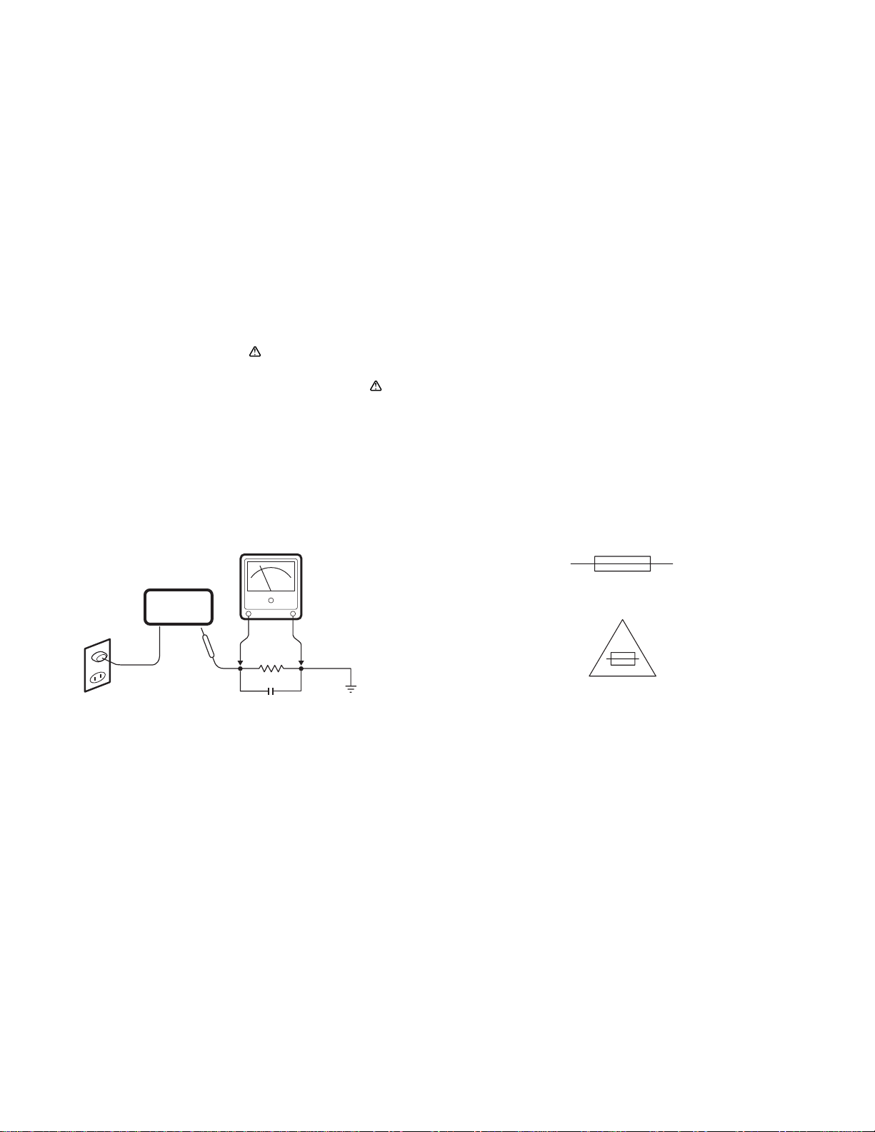
3. Before returning the set to the customer, always perform
an AC leakage current check on the exposed metallic parts
of the cabinet, such as terminals, screwheads, metal
overlays, etc. to be sure that the set is safe to operate
without the danger of electrical shock, Plug the AC line
cord directly into a 120 V AC outlet. (Do not use a line
isolation transformer during this check.) Use an AC voltmeter
with a sensitivity of 5000 ohms per volt (or more) as follows:
Connect a 1500 ohms, 10 watt resistor, paralleled by a 0.15
mfd, 150 VAC capacitor, between a known good earth
ground (water pipe, conduit, etc.) and the exposed metallic
parts, one at a time. Measure the AC voltage across the
1500 ohms resistor and 0.15 mfd capacitor combination.
Reverse the AC plug at the AC outlet and repeat the AC
voltage measurements for each exposed metallic part.
The measured voltage must not exceed 300 mVrms. This
corresponds to 200 µA AC. Any value exceeding this limit
constitutes a potential shock hazard and must be corrected
immediately.
4. Fuse symbol marks.
For CANADA
AC OUTLET
Color LCD
monitor
1500 Ohm
10 Watt
0.15uF 150 VAC
Place this probe on each
exposed metallic part
Voltmeter Hook-up for Leakage Current Check
Good earth ground such as
a water pipe,conduit etc.
For U.S.A.
Fuse rating is marked at
adjacent fuse.
UNDERWRITERS LABORATORIES Standard
CAUTION "Risk of fire-replace fuse as marked"
- 2 -
WARNING
Do not use solder containing lead.
This product has been manufactured using lead-free
solder in order to help preserve the environment.
Because of this, be sure to use lead-free solder when
carrying out repair work, and never use solder
containing lead.
Lead-free solder has a melting point that is 30 - 40°C (86 104°F) higher than solder containing lead, and moreover it
does not contain lead which attaches easily to other metals.
As a result, it does not melt as easily as solder containing
lead, and soldering will be more difficult even if the
temperature of the soldering iron is increased.
The extra difficulty in soldering means that soldering time
will increase and damage to the components or the circuit
board may easily occur.
Because of this, you should use a soldering iron and
solder that satisfy the following conditions when carrying out
repair work.
Note:
If replacing existing solder containing lead with lead-free
solder in the soldered parts of products that have been
manufactured up until now, remove all of the existing solder
at those parts before applying the lead-free solder.
Soldering iron
Use a soldering iron which is 70 W or equivalent, and
which lets you adjust the tip temperature up to 450°C
(842°F). It should also have as good temperature recovery
characteristics as possible.
Set the temperature to 350°C (662°F) or less for chip
components, to 380°C (716°F) for lead wires and similar,
and to 420°C (788°F) when installing and removing shield
plates.
The tip of the soldering iron should have a C-cut shape or
a driver shape so that it can contact the circuit board as flat
or in a line as much as possible.
Solder
Use solder with the metal content and composition ratio by
weight given in the table below. Do not use solders which
do not meet these conditions.
Metal content Tin (Sn) Silver (Ag) Copper (Cu)
Composition
ratio by weight
96.5% 3.0% 0.5%
Lead-free solder is available for purchase as a service tool.
Use the following part number when ordering:
Part name: Lead-free solder with resin (0.5 mm dia., 500 g)
Part number: VJ8-0270
- 3 -
SPECIFICATIONS
Display type : SXGA a-Si TFT LCD
Color system : PAL/NTSC (Automatic detection)
LCD display : 19” active matrix TFT LCD panel
Viewable size (H x V) : 376 x 301 mm/14.8 x 11.9 in. (4:3)
Pixel pitch (H x V) : 0.294 x 0.294 mm/0.012 x 0.012 in.
Horizontal resolution : 1280 x 1024, PAL: 620 NTSC: 600 TV lines (Y/C input mode)
Viewing angle degree : Left/Right/Up/Down: 80°
Scanning frequency : Horizontal 30k - 81kHz, Vertical 56 - 75 Hz
Contrast ratio : 1000:1
Brightness : 300 cd/m / 359 cd/yd
2
Response time Tr/Tf : 1.3/3.7 ms
Display color : 16.7 M
Display monitor timing : VESA compatible (VGA mode)
Display mode : Video A, Video B, S-Video, VGA
Input connector
Video signal (BNC IN) : Composite sync signal, 1.0 Vp-p, 75 ohms BNC connector x 2
S-Video signal (Y/C IN) : Separate Y/C signal, mini-DIN connector
Y signal : 1.0 Vp-p, 75 ohms negative sync
C signal : 0.286 Vp-p, 75 ohms negative sync
Audio signal (AUDIO IN) : -6.0 dBs (400 mVrms), 2W (1W + 1W) stereo, RCA pin x 2
VGA signal (VGA IN) : VGA monitor connector (15-pin)
Red signal, Green signal, Blue signal : 0.7 Vp-p, 75 ohms positive sync
Output connector
Video signal (BNC OUT) : Composite sync signal, 1.0 Vp-p, 75 ohms BNC connector x 2
S-Video signal (Y/C OUT) : Separate Y/C signal, mini-DIN connector
Y signal : 1.0 Vp-p, 75 ohms negative sync
C signal : 0.286 Vp-p, 75 ohms negative sync
Menu language : English/ French/ German/ Spanish/ Italian/ Portuguese/ Dutch/ Swedish/ Russian/ Korean/ Japanese
Power input : AC 100 V - 240 V
Operating condition : Temperature : 0°C - +40°C/32°F - 104°F
Humidity : 10 - 90 % (non-condensation)
Storage condition : Temperature : -20°C - +45°C/-4°F - +113°F
Humidity : 5 - 95 %
Power consumption : Approx. 42 W (0.7 A)
Weight : Approx. 6.9 kg/15.2 lbs.
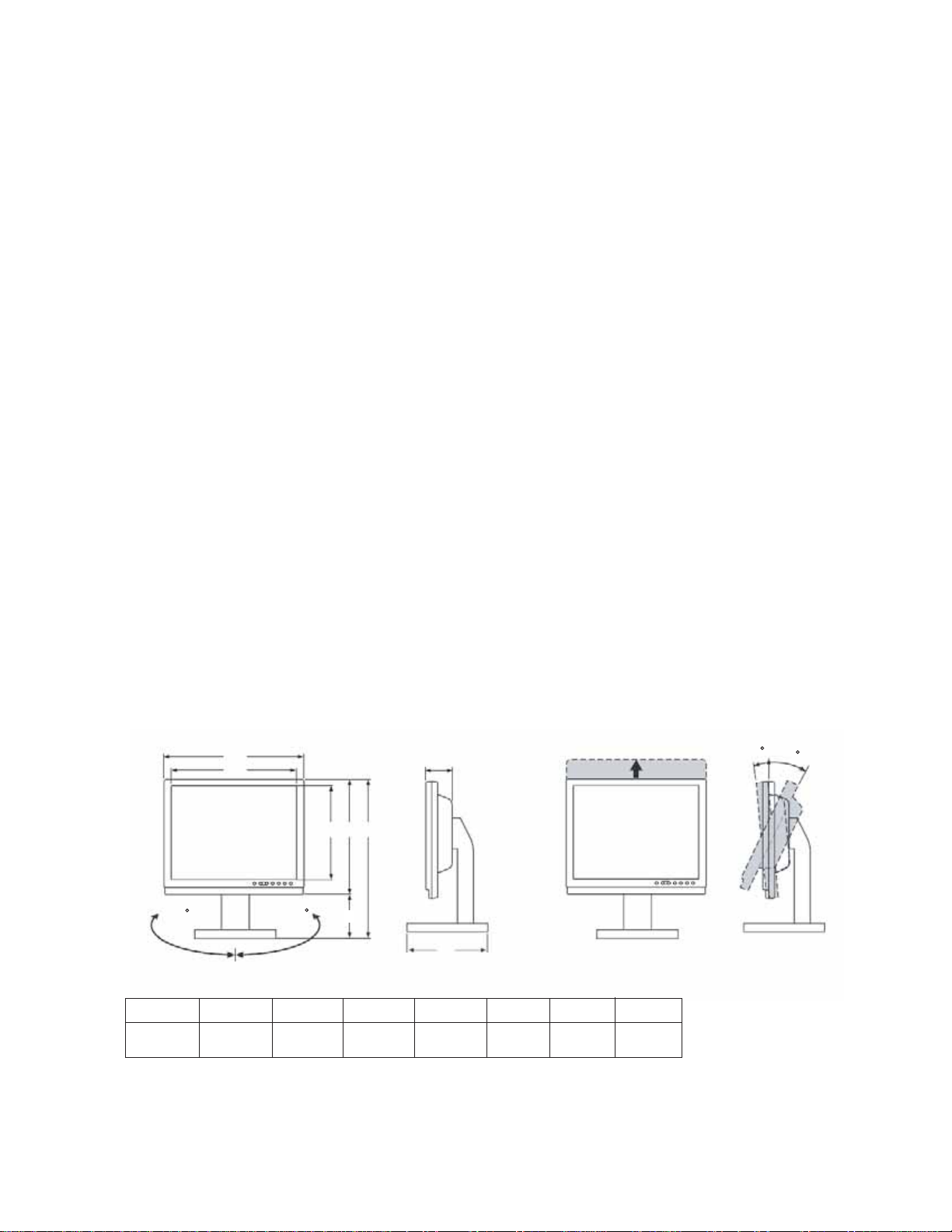
Dimensions :
2
165
A
B
(Swivel)
165
C D E
F
G
H
100 (3.9)
(Lift)
A B C D E F G H
412 (16.2) 378 (14.9) 303 (11.9) 361 (14.2) 398 (15.7) 37 (1.5) 69 (2.7) 220 (8.7)
Note
Unit: mm (inch)
When adjusting the screen tilt, please make sure not to damage the screen.
After adjusting the tilt, check the cables to ensure the monitor is not pulled over.
- 4 -
25
5
(Tilt)
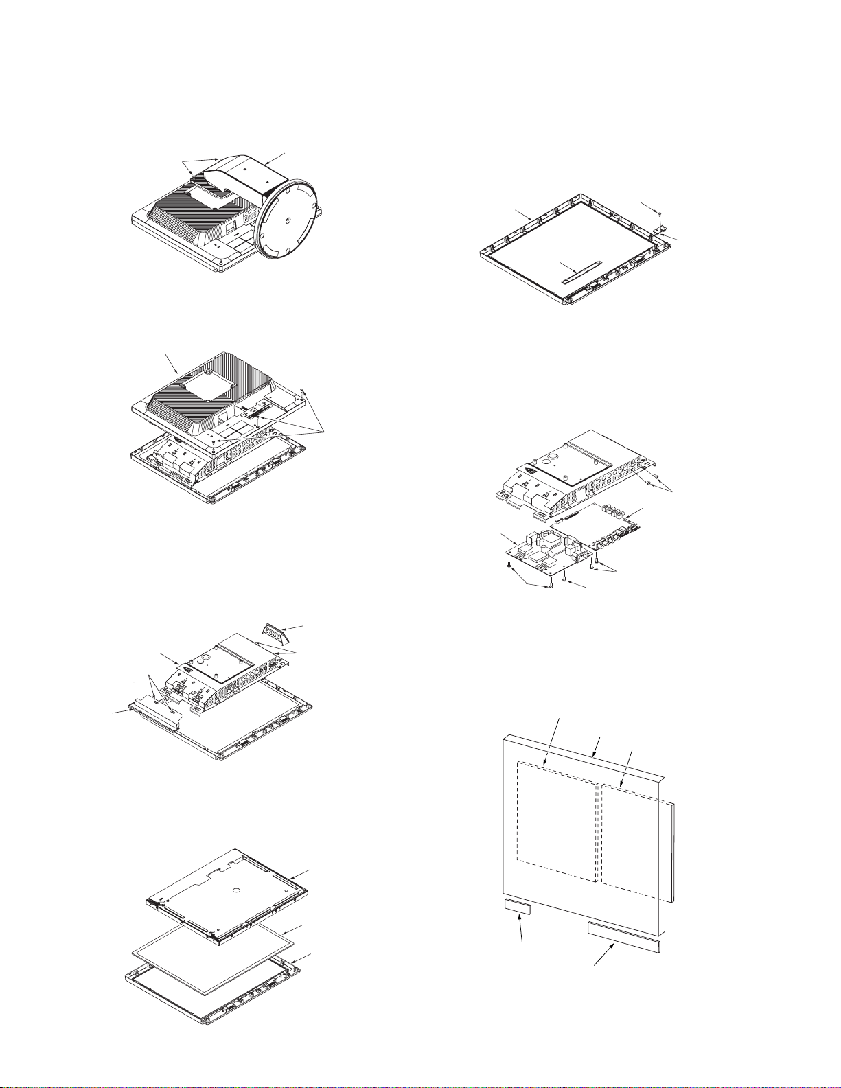
1. DISASSEMBLY
1-1. DISASSEMBLY
1. Remove the two screws 4 x 10.
2. Remove the ass’y stand P.
1
3. Remove the three screws 3 x 10.
4. Remove the ass’y cover P-rear.
4
5. Release the two hooks.
6. Remove the cover jack.
7. Release the two hooks.
8. Remove the shield-lamp.
9. Remove the ass’y chassis shield.
13. Remove the screw 3 x 8.
14. Remove the ass’y IR board.
2
15. Remove the ass’y FUNCTION board.
16. Cover front.
16
15
13
14
17. Remove the two screws.
18. Remove the four screws 3 x 8.
19. Remove the screw 4 x 8.
20. Remove the IP board.
21. Remove the MAIN board.
3
17
21
20
19
19
18
9
7
8
10. Remove the LCD panel.
11. Remove the glass protection.
12. Ass’y cover front.
6
5
1-2. BOARD LOCA TION
MAIN board
LCD panel
IP board
10
11
12
IR board
FUNCTION board
- 5 -
2. ADJUSTMENT
This section describes to adjust LCD monitor after replacing FLASH, Main board or Panel.
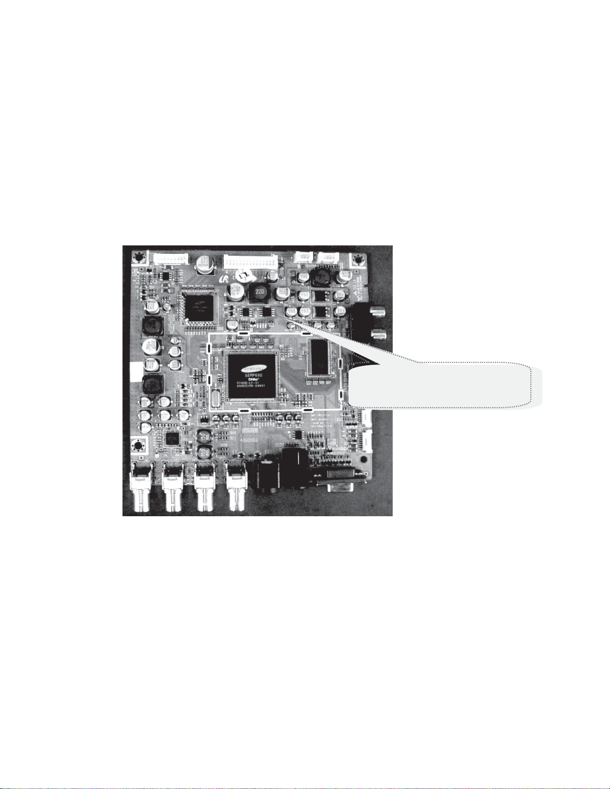
2-1. Program Upgrade
Change MICOM
If the similer happenings occur, FLASH can be changed
EX1) When screen appears but remote control and function key aren’t working
EX2) When LED is on but the screen doesn’t appear
EX3) After mass production, when the micom program version is up-graded
*FLASH replacement can be done when Service Bulletin issue is in practice.
The process of working need to be prepare on Service Bulletin.
Upgraded
After disassembling the set (refer to SET disassemble), remove the FLASH in the exist IC6003 and replace new FLASH.
-Use appropriate JIG or any sharp tool and place in the both corners to assist in removing.
(Be aware! If the socket cause any damage after replacement the monitor will not function properly.)
-When inserting, attend to IC direction and press with suitable amount of strength.
-After replacement, in case of EEPROM Clear, enter to Factory mode and perform into action.
FLASH
- 6 -
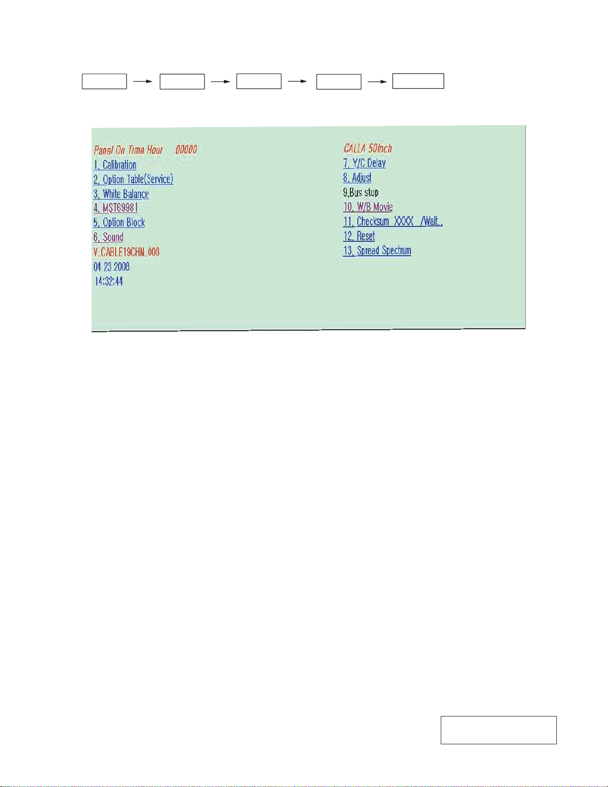
2-2. Factory Mode Adjustments
2-2-1. Factory Mode Admission
MUTE
2-2-2. Service Mode Menu
Calibration
1. AV calibration
2. COMP calibration
3. PC calibration
4. HDMI calibration
White Balance
1. Sub-briteness
2. R-offset
3. G-offset
4. B-offset
5. Sub-contrast
6. R-gain
7. G-gain
8. B-gain
1
Option Table (Service)
1. Ready
2. Inch option
3. Panel vender
4. Panel type
5. Model option
6. Anynet +
7. Auto power
8. Nordic
9. LNA menu
10. TTX on/off
11. TTX list
12. Carrier must
13. High deviation
14. Volume curve
15. HDMI hotplug
16. HDMI hotplugclkcontrol
17. HDMI hotplugdelay
18. Hotel option
19. Shop mode
20. Color space
21. PC ident
22. Language
23. Ch. table
24. TTX group
25. iDTV country
8
2
Adjust
1. V Mute time
2. Dynamic contrast
3. Dynamic dimming
4. Dynamic CE
5. LNA plus
6. Magazine LNA
7. Pixelshift test
8. Debug
9. ACR
10. D-watchdog
11. UART select
12. FBE select
13. Tuner
14. Tuner TOP semco
15. Tuner TOP alp s
16. D.Gamma
17. M.Gamma
Power on
W/B Movie
1. WB movie
2. Color mode
3. Color tone
4. Msub bright
5. Msub contr
6. W1 R gain
7. W1 B gain
8. W1 R offset
9. W1 B offset
10. W2 R gain
11. W2 B gain
12. W2 R offset
13. W2 B offset
14. NO R gain
15. NO B gain
16. NO R offset
17. NO B offset
18. C2 R gain
19. C2 B gain
20. C2 R offset
21. C2 B offset
22. Movie contrast
23. Movie brightness
24. Movie color
25. Movie sharpness
26. Movie color tone
W1 Warm1 W2 Warm2
NO Normal C2 Cool2
- 7 -
 Loading...