

Sanyo VMC-L1017A Service Manual
SERVICE MANUAL
FILE NO.
Color TFT LCD monitor
CONTENTS
SPECIFICATIONS.....................................3
1. DISASSEMBL Y .....................................4
2. ADJUSTMENT ..................................... 7
3. P AR TS LIST .........................................8
CIRCUIT DIAGRAMS &
PRINTED WIRING BOARDS ................. C1
VMC-L1017 A
(Product Code : 114 954 13)
(U.S.A., Canada)
VMC-L1019 A
(Product Code : 114 954 14)
(U.S.A., Canada)
PRODUCT SAFETY NOTICE
The components designated by a symbol ( ! ) in this schematic diagram designates components whose value are of
special significance to product safety. Should any component designated by a symbol need to be replaced, use only the
part designated in the Parts List. Do not deviate from the resistance, wattage, and voltage ratings shown.
RoHS
This product does not contain any hazardous substances prohibited by the RoHS Directive.
WARNING
You are requested to use RoHS compliant parts for maintenance or repair.
You are requested to use lead-free solder.
(This product has been manufactured using lead-free solder. Be sure to follow the warning given on page 2 when carrying
out repair work.)
NOTE: 1. Parts order must contain model number, part number, and description.
2. Substitute parts may be supplied as the service parts.
3. N.S.P. : Not available as service parts.
Design and specifications are subject to change without notice.
L8MAJ/USH, L8MAK/USH (R)
REFERENCE No.SM5310693
WARNING
Do not use solder containing lead.
This product has been manufactured using lead-free
solder in order to help preserve the environment.
Because of this, be sure to use lead-free solder when
carrying out repair work, and never use solder
containing lead.
Lead-free solder has a melting point that is 30 - 40°C (86 104°F) higher than solder containing lead, and moreover it
does not contain lead which attaches easily to other metals.
As a result, it does not melt as easily as solder containing
lead, and soldering will be more difficult even if the
temperature of the soldering iron is increased.
The extra difficulty in soldering means that soldering time
will increase and damage to the components or the circuit
board may easily occur.
Because of this, you should use a soldering iron and
solder that satisfy the following conditions when carrying out
repair work.
Note:
If replacing existing solder containing lead with lead-free
solder in the soldered parts of products that have been
manufactured up until now, remove all of the existing solder
at those parts before applying the lead-free solder.
Soldering iron
Use a soldering iron which is 70 W or equivalent, and
which lets you adjust the tip temperature up to 450°C
(842°F). It should also have as good temperature recovery
characteristics as possible.
Set the temperature to 350°C (662°F) or less for chip
components, to 380°C (716°F) for lead wires and similar,
and to 420°C (788°F) when installing and removing shield
plates.
The tip of the soldering iron should have a C-cut shape or
a driver shape so that it can contact the circuit board as flat
or in a line as much as possible.
Solder
Use solder with the metal content and composition ratio by
weight given in the table below. Do not use solders which
do not meet these conditions.
Metal content Tin (Sn) Silver (Ag) Copper (Cu)
Composition
ratio by weight
96.5% 3.0% 0.5%
Lead-free solder is available for purchase as a service tool.
Use the following part number when ordering:
Part name: Lead-free solder with resin (0.5 mm dia., 500 g)
Part number: VJ8-0270
- 2 -
SPECIFICATIONS
Color system : NTSC, PAL
LCD display : 17” active matrix TFT LCD panel (VMC-L1017 A), 19” active matrix TFT LCD panel (VMC-L1019 A)
Screen size : 432 mm diagonal (VMC-L1017 A), 480 mm diagonal (VMC-L1019 A)
Viewable size (H x V) : 337 x 270 mm (5:4) (VMC-L1017 A), 376 x 301 mm (5:4) (VMC-L1019 A)
Pixel pitch (H x V) : 0.264 x 0.264 mm (VMC-L1017 A), 0.294 x 0.294 mm (VMC-L1019 A)
Horizontal resolution : 500 TV lines or more (Y/C input mode)
1280 x 1024
Scanning frequency : Horizontal 30k - 80kHz, Vertical 56 - 75 Hz
Contrast ratio : 500:1
Brightness : 300cd/m
Response time Tr/Tf : 2/6 ms
Display color : 16.2 M
View angle L/R : 75°/75°
View angle Up/Down : 70°/60°
Display monitor timing : VESA compatible
Display mode : VIDEO & S-VIDEO & VGA
Input connector
Video signal (BNC IN) : Composite sync signal, 1.0 Vp-p, 75 BNC connector
S-Video signal (Y/C IN) : Separate Y/C signal, mini-DIN connector
Y signal : 1.0 Vp-p, 75 negative sync
C signal : 0.286 Vp-p, 75 negative sync
Audio signal (AUDIO IN) : -6 dBs (400 mVrms), RCA pin
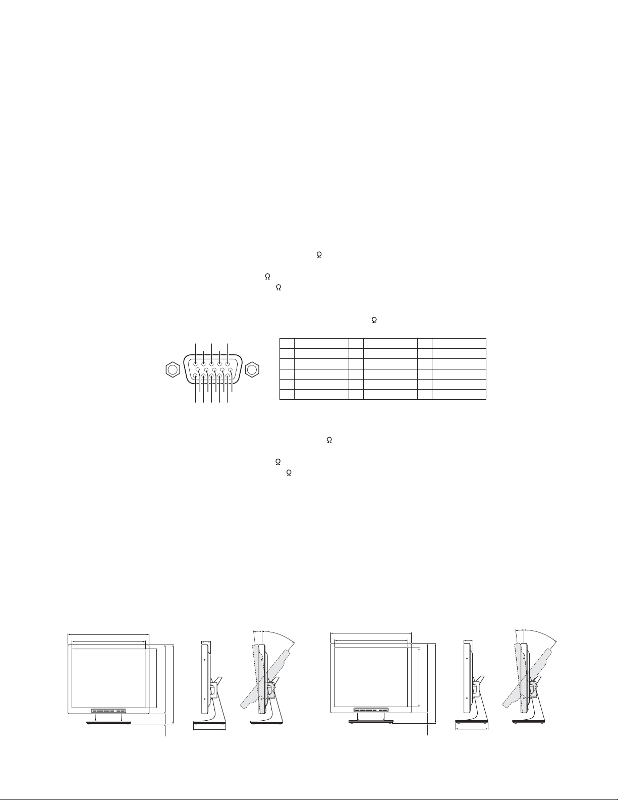
VGA signal (VGA IN) : VGA monitor connector (15-pin)
Red signal, Green signal, Blue signal : 0.7 Vp-p, 75 , positive sync
2
54321
10 9 8 7 6
15 14 13 12 11
Pin No.
1
2
3
4
5
Signal Signal Signal
Red signal
Green signal
Blue signal
No use
No use
Pin No.
GND (Red)
6
GND (Green)
7
GND (Blue)
8
No use
9
GND (sync)
10
Output connector
Video signal (BNC OUT) : Composite sync signal, 1.0 Vp-p, 75 BNC connector
S-Video signal (Y/C OUT) : Separate Y/C signal, mini-DIN connector
Y signal : 1.0 Vp-p, 75 negative sync
C signal : 0.286 Vp-p, 75 negative sync
Audio signal (AUDIO OUT) : -6 dBs (400 mVrms), RCA pin
Menu language : English/ Chinese/ French/ German/ Spanish/ Italian/ Japanese
Audio power output : Approx. 1 W
Power input : DC 12 V/ 4.16 A
Power consumption : Approx. 50 W
Operating condition : Temperature : 0 - 40°C
Humidity : 20 - 85 % (non-condensation)
Storage condition : Temperature : -20 - 60°C
Humidity : 20 - 85 % (non-condensation)
Weight (Adaptor included) : 5.0 kg (VMC-L1017 A), 6.1 kg (VMC-L1019 A)
Dimensions :
VMC-L1017 A VMC-L1019 A
(Unit: mm)
375.0
341.0
41.6
5°
40°
(Unit: mm)
421.2
379.4
Pin No.
11
12
13
14
15
No use
SDA
H sync
V sync
SCL
44.6
5°
45°
273.4
318.0
52.0
370.0
170.0
Side viewFront view Angles of adjustment
- 3 -
304.0
353.9
52.0
405.6
170.0
Side viewFront view Angles of adjustment
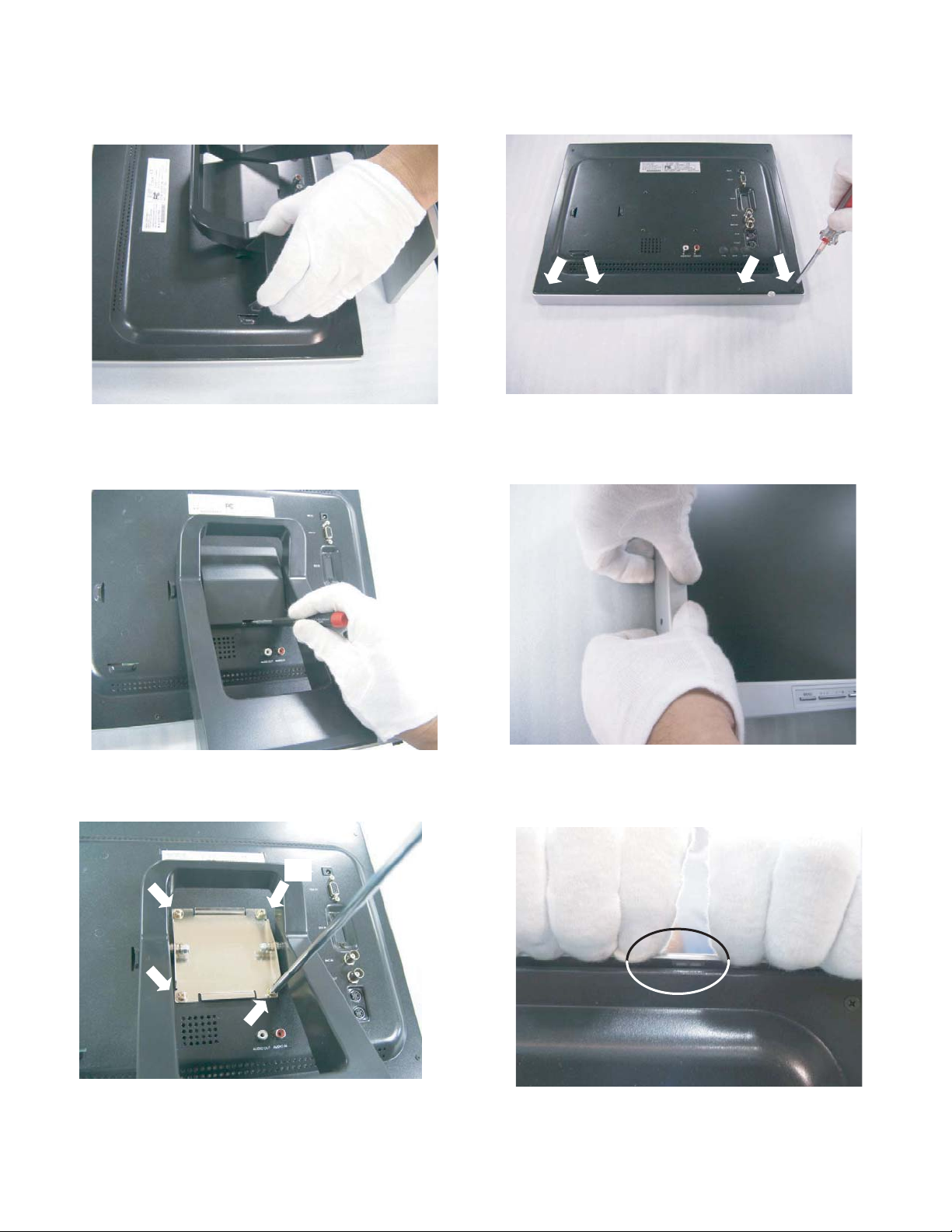
1. DISASSEMBLY
(1)
(1)
(1)
(1)
1-1. DISASSEMBLY
1. Take off the adapter case.
2. Take off the stand cover.
4. Take off the four screws(2) and front panel.
(2)
Caution: Dismount the front panel, both bottom left and
right side evenly.
(2)
3. Take off the four screws(1) and stand.
Caution: Make sure to dismount the front panel from the
clips.
- 4 -
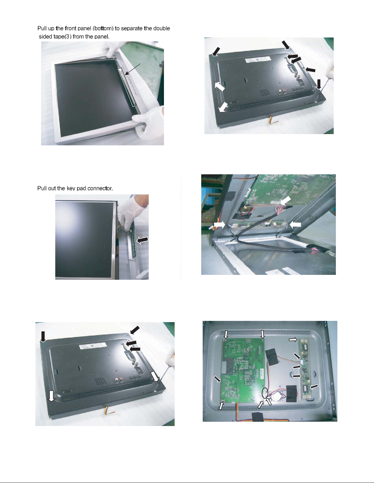
5.
8. Take off the six screws(7) and two bolts(8). (VMC-L1019 A)
(7)
(7)
(8)
(3)
(7)
(7)
9. Pull out 3 connectors (see the arrow pointed) (9) to dismount
the LCD panel.
6.
(9)
(4)
1.FUNCTION board(4).
7. Take off the four screws(5) and two bolts(6). (VMC-L1017 A)
(5)
(5)
(6)
(3)
(6)
(5)
(5)
(9)
10. Pull out the connectors (see the arrow pointed)(10) to the
MAIN board and INVERTER board.
(11)
(11)
(9)
(13)
(10)
(12)
(13)
(14)
(13)
(11)
(10)
(11)
1.Take off the four screws(11) and MAIN board(12).
2.Take off the three screws(13) and INVERTER
board(14).
- 5 -
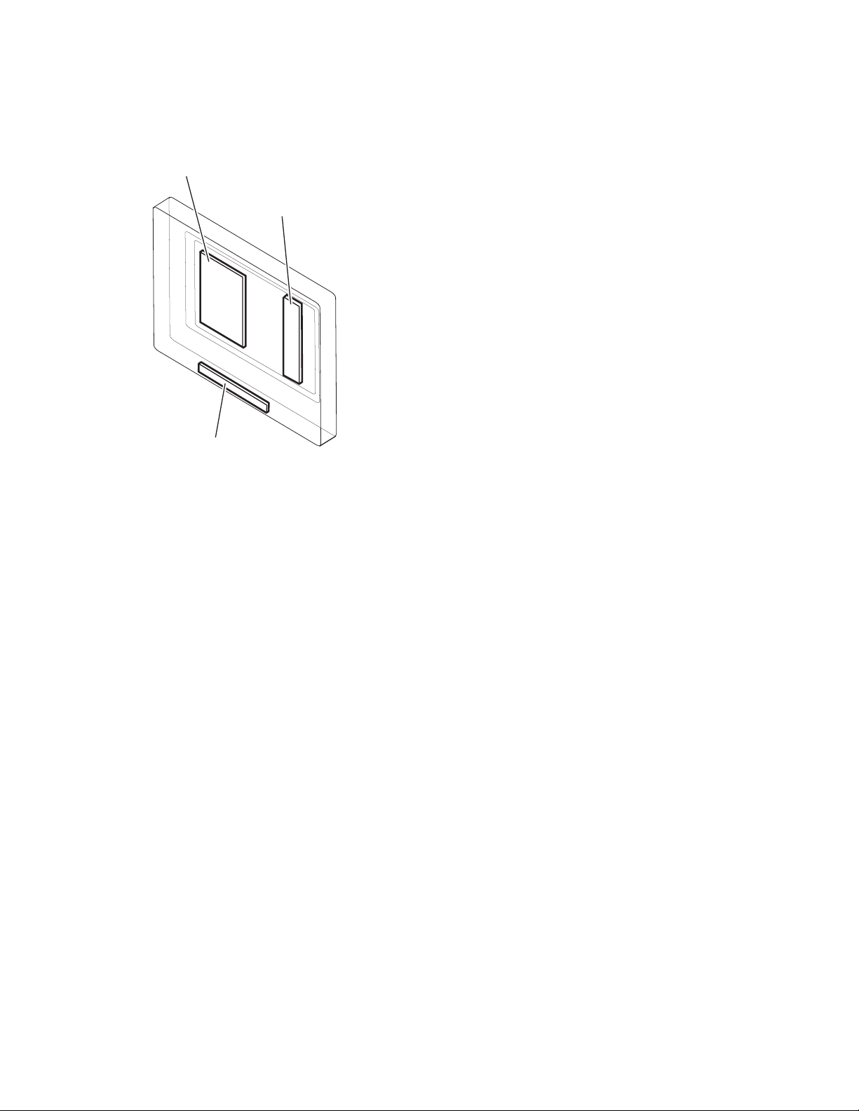
1-2. BOARD LOCA TION
MAIN BOARD
FUNCTION BOARD
INVERTER BOARD
- 6 -
2. ADJUSTMENT
INSTRUMENT: (A)VGA Signal Generator, (B) Color Analyzer CA110
INPUT SIGNAL: (a)VGA, (b)Inner Full White Signal
TIMING: (1)1280 x 1024/ 75Hz
Check Item
No
MCU Version
1
Brightness
2
Checking
9300K White
3
Balance
6500K White
4
Balance
Pattern
Full White
Full White
Full White
Signal
(a)
(a)(b)
(a)(b)
(a)(b)
Instrument
(A)
(A)(B)
(A)(B)
(A)(B)
Timing
(1)
(1)
(1)
(1)
Method / Procedure
1. Connect to VGA while power on.
2. Press (+), (-) and menu sequentially while power
off.
3. Check MCU version.
1. Press Auto key until display turns into full white
signal.
2. Set up VGA Color to be User color.
3. Brightness adjustment: (depend by panel)
3-1 Adjust Inverter to 51, ensure the Y value of
brightness is not less than the TYP value of
panel.
3-2 If Y value less than the panel’s TYP value,
make sure the Y value over than 80% of the
TYP value, otherwise NG.
Adjust R and G value until color temperature
x=283 ± 15, y=298 ± 15
Adjust R and G value until color temperature
x=313 ± 15, y=329 ± 15
VGA Color
5
Temperature
Setup
VIDEO Color
6
Temperature
Setup
Factory Mode
7
& OSD Color
Temperature
Checking
Remark:
VMC-L1017 A/L1017P
CMO (M170E5-L09)
(P#:501-1707-071R)
TYP=300 cd/m²
Min=230 cd/m²
Full White
Full White
Full White
VMC-L1019 A/L1019P
CMO (M190E5-L0A)
(P#:501-1907-111R)
TYP=300 cd/m²
Min=240 cd/m²
(a)(b)
(a)(b)
(a)
(A)
(A)
(A)
(1)
(1)
(1)
User Color
(For VMC-L1017 A,L1019 A/VMC-L1017P,L1019P)
VMC-L1017 A, VMC-L1019 A: 9300K
VMC-L1017P, VMC-L1019P: 6500K
1. Under factory mode, make sure “FORCUS LL
MODE” is “OFF”.
2. After factory mode set-up, press menu. The
selected values will be saved automatically while
menu closes.
3. Open OSD menu, select recall and ensure the
normality of OSD color temperature.
- 7 -

3. PARTS LIST (R)
LOCATION PARTS NO. DESCRIPTION LOCATION PARTS NO. DESCRIPTION
ACCESSORIES & PACKING MATERIALS
645 092 1933 USER MANUAL HCP-15/LCP-17.19
645 087 9388 VGA CABLE 2919/ 1300+-50MM
645 092 8178 CARTON LCP-17W01 II,VMC-L1017 A ONLY
645 092 8161 CARTON LCP-19W01 II,VMC-L1019 A ONLY
645 087 9326 CARTON LCP-17W01 2 IN 1,
VMC-L1017 A ONLY
645 092 4033 CARTON LCP-19W01,VMC-L1019 A ONLY
645 087 9418 HANDLE LP-10R01
645 087 9449 PE BAG 50*70CM 0.04MM,VMC-L1017 A ONLY
645 092 4040 PE BAG 800*580*0.04T,VMC-L1019 A ONLY
CABINET & CHASSIS PARTS
1 645 087 8961 FRONT PANEL LCP-17W01 ABS,
VMC-L1017 A ONLY
1 645 092 3975 FRONT PANEL LCP-19W01 ABS,
VMC-L1019 A ONLY
2 645 087 9029 OSD FUNCTION PANEL LCP-19W01
3 645 087 9043 FUNCTION KNOB LCP-19W01 ABS
4 645 087 9050 LED LENS LCP-17W01
5 645 087 9364 DIGI.FUNCTION STICKER LCP17W01 (N.S.P.)
6 645 088 0230 FUNCTION BOARD LCP-17W01
7 645 088 0674 LCD PANEL 17' TFT LVDS A,
VMC-L1017 A ONLY
7 645 092 4064 LCD PANEL 19' TFT LVDS A,
VMC-L1019 A ONLY
8 645 087 9036 PANEL BRACKET LCP-17W01 SECC,
VMC-L1017 A ONLY
8 645 092 3999 FIXED BRACKET LCP-19W01,
VMC-L1019 A ONLY
9 645 092 1971 MAIN BOARD LCP-17W01 N3
10 645 092 3951 LCD INVERTER TI-100 N1
11 645 087 9258 MYLAR FILM 195MM*94MM*0.3T
12 645 092 4071 L/W HOUSING 1571#28AWG+CORE
13 645 092 2022 L/W HOUSING UL1007#28 O/2C/B
14 645 092 2015 FLAT CABLE L=310MM CORE 6PIN
15 645 088 0360 SPEAKER ASSíY LCP-15V01
16 645 092 3968 REAR CABINER LCP-17W01,
VMC-L1017 A ONLY
16 645 092 3982 REAR CABINER LCP-19W01,
VMC-L1019 A ONLY
17 645 087 9012 ADAPTER CASE LCP-17W01 RAL9011
18 645 087 9401 ADAPTER 12V/4.16A/180CM/5.5/90
19 645 087 9296 ID LABEL 100*25MM (N.S.P.)
20 645 087 9210 DVI CONNECTOR HOLE COVER HCP15
21 645 087 9227 HOLD PLUG M-10
22 645 087 9067 HINGE LCP-17W01,VMC-L1017 A ONLY
22 645 092 4002 HINGE LP-15R01,VMC-L1019 A ONLY
23 645 087 9005 BASE ARM LCP-17W01
24 645 087 9081 HINGE COVER LCP-17W01
25 645 087 8992 BASE COVER LCP-17W01 ABS
26 645 087 8985 BASE PLATE LCP-17W01 SECC
27 645 087 9203 FOOT PAD LP-12
28 645 087 9425 PVC 360MM*290MM*0.1T,VMC-L1017 A ONLY
28 645 092 4989 PVC 390MM*320MM*0.1T,VMC-L1019 A ONLY
29 645 087 9104 PH SCREW 2*6MM
30 645 087 9098 PH SCREW M3*4MM,VMC-L1017 A ONLY
30 645 092 4019 BH SCREW 3*6MM,VMC-L1019 A ONLY
31 645 087 9197 CONNECTOR SCREW 5.2 M3*6MM
32 645 087 9159 NUT 3*6MM
33 645 087 9173 CONNECTOR SCREW 3*4.75*11.8MM
34 645 087 9180 BINDING HEAD SCREW M3*4MM
35 645 087 9166 BIND. HEAD-SELF-TAP. SCREW 3*8
36 645 087 9142 SCREW+WASHER 4*14MM
37 645 087 9135 SCREW+WASHER 4*8
38 645 087 9128 FH SCREW 3*10MM
39 645 087 9234 HOLD PLUG LCP-19 7.0*6.3L
40 645 087 9111 PH W/W SCR. 3*8MM
41 645 087 9265 3M VHB TAPE 7MM*66M 3M 4920
42 645 087 9241 MYLAR FILM 188MM*123MM*0.3T
43 645 087 9074 PCB HOLDER LCP-19 SECC
44 645 087 9302 ID LABEL 50*15MM 25U (N.S.P.)
45 645 092 1858 COPPER TAPE 50*25MM
46 645 092 1865 COPPER TAPE 50*70*0.06MM
47 645 092 1827 SHIELD GASKET 240MM*8MM*4T
48 645 092 1889 COPPER TAPE 240MM*50MM*0.06T,
VMC-L1019 A ONLY
49 645 092 1872 COPPER TAPE 145*25*0.06MM,
VMC-L1019 A ONLY
8
 Loading...