

SERVICE MANUAL
FILE NO.
Color Video Monitor
CONTENTS
SPECIFICATIONS .................................................................... 3
1. OPERATING INSTRUCTIONS ............................................. 4
2. SERVICE ADJUSTMENTS ................................................... 6
3. PARTS LIST ....................................................................... 10
CIRCUIT DIAGRAMS
VMC-8618
(Product Code : 114 950 71)
(U.S.A, Canada)
VMC-8619P
(Product Code : 114 950 74)
(Europe)
(Product Code : 114 950 76)
(U.K.)
(Product Code : 114 950 78)
(Australia)
NOTE: 1. Parts order must contain model number, part number, and description.
2. Substitute parts may be supplied as the service parts.
3. N.S.P. : Not available as service parts.
Design and specifications are subject to change without notice.
L8MV5/US,XE,UK,AU
REFERENCE No.SM5310261
SAFETY PRECAUTIONS
WARNING:
Service should not be attempted by anyone unfamiliar with the necessary precautions for this recording or playback
equipment. The following precautions are necessary during servicing:
1. Many electrical and mechanical parts in this recorder have
special safety-related characteristics for providing protection against shock, fire and other hazards. These characteristics often go unnoticed in a visual inspection, and the
protection afforded by them cannot necessarily be obtained by using replacement components with higher ratings (voltage, wattage, etc.).
2. Replacement parts having special safety-related characteristics are identified in this manual, and in the schematic
diagrams, by the symbol ! . These components have
values that are of special significance to product safety.
Should any component (identified by the symbol ) need
to be replaced, use only the part designated in the parts
List. Do not deviate from the specified resistance, wattage,
and voltage ratings.
Video
Monitor
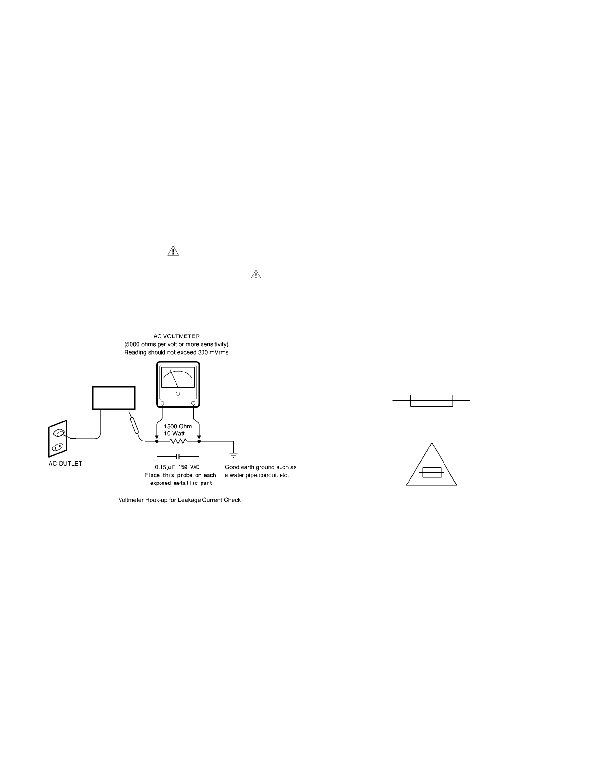
3. Before returning the set to the customer, always perform an
AC leakage current check on the exposed metallic parts of
the cabinet, such as terminals, screwheads, metal overlays, etc. to be sure that the set is safe to operate without
the danger of electrical shock, Plug the AC line cord directly
into a 120 V AC outlet. (Do not use a line isolation transformer during this check.) Use an AC voltmeter with a
sensitivity of 5000 ohms per volt (or more) as follows:
Connect a 1500 ohms, 10 watt resistor, paralleled by a 0.15
mfd, 150 VAC capacitor, between a known good earth
ground (water pipe, conduit, etc.) and the exposed metallic
parts, one at a time. Measure the AC voltage across the
1500 ohms resistor and 0.15 mfd capacitor combination.
Reverse the AC plug at the AC outlet and repeat the AC
voltage measurements for each exposed metallic part. The
measured voltage must not exceed 300 mVrms. This
corresponds to 200 µA AC. Any value exceeding this limit
constitutes a potential shock hazard and must be corrected
immediately.
4. Fuse symbol marks.
For CANADA
For U.S.A.
Fuse rating is marked at
adjacent fuse.
UNDERWRITERS LABORATORIES Standard
CAUTION "Risk of fire-replace fuse as marked"
– 2 –
SPECIFICATIONS
Color system :
Picture tube :
Resolution :
Input terminals :
Outout terminals :
Overscan or underscan selection:
Audio output :
Speaker :
Power source :
Power consumption :
Ambient operating temperature :
Ambient operating humidity :
Dimension (W x H x D ) :
Weight :
PAL/NTSC, selected automatically
18 incht (VMC-8618) , 19 incht (VMC-8619P)
More than 800 TV lines
Separate Y/C signal, mini-DIN 4-pin connector (1)
Y signal: 1.0 Vp-p, 75 ohm negative sync
C signal: 0.286 Vp-p, 75 ohm negative sync, bridge connection possible
Composite sync signal: 1.0 Vp-p, 75 ohm BNC connector (2)
Audio signal: -6dBs (400 mVrms), RCA pin (3), bridge connection possible
Separate Y/C signal, mini-DIN 4-pin connector (1)
Y signal: 1.0 Vp-p, 75 ohm negative sync
C signal: 0.286 Vp-p, 75 ohm negative sync, bridge connection possible
Composite sync signal: 1.0 Vp-p, 75 ohm BNC connector (2),
automatic temination setting
Audio signal: -6dBs (400 mVrms), RCA pin (3), bridge connection possible
YES
1 W
Variable round x 1
100 to 240 V AC, 50/60 Hz
95 Watts
-10 °C to 45 °C storage temperature
10 % to 90 %
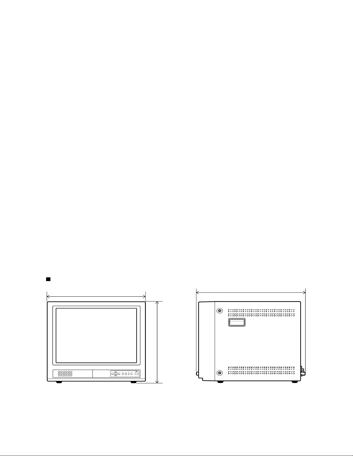
448 x 443 x 447 mm
25kg
Dimensions
W
D
H
Fig. 1
– 3 –
1. OPERATING INSTRUCTIONS
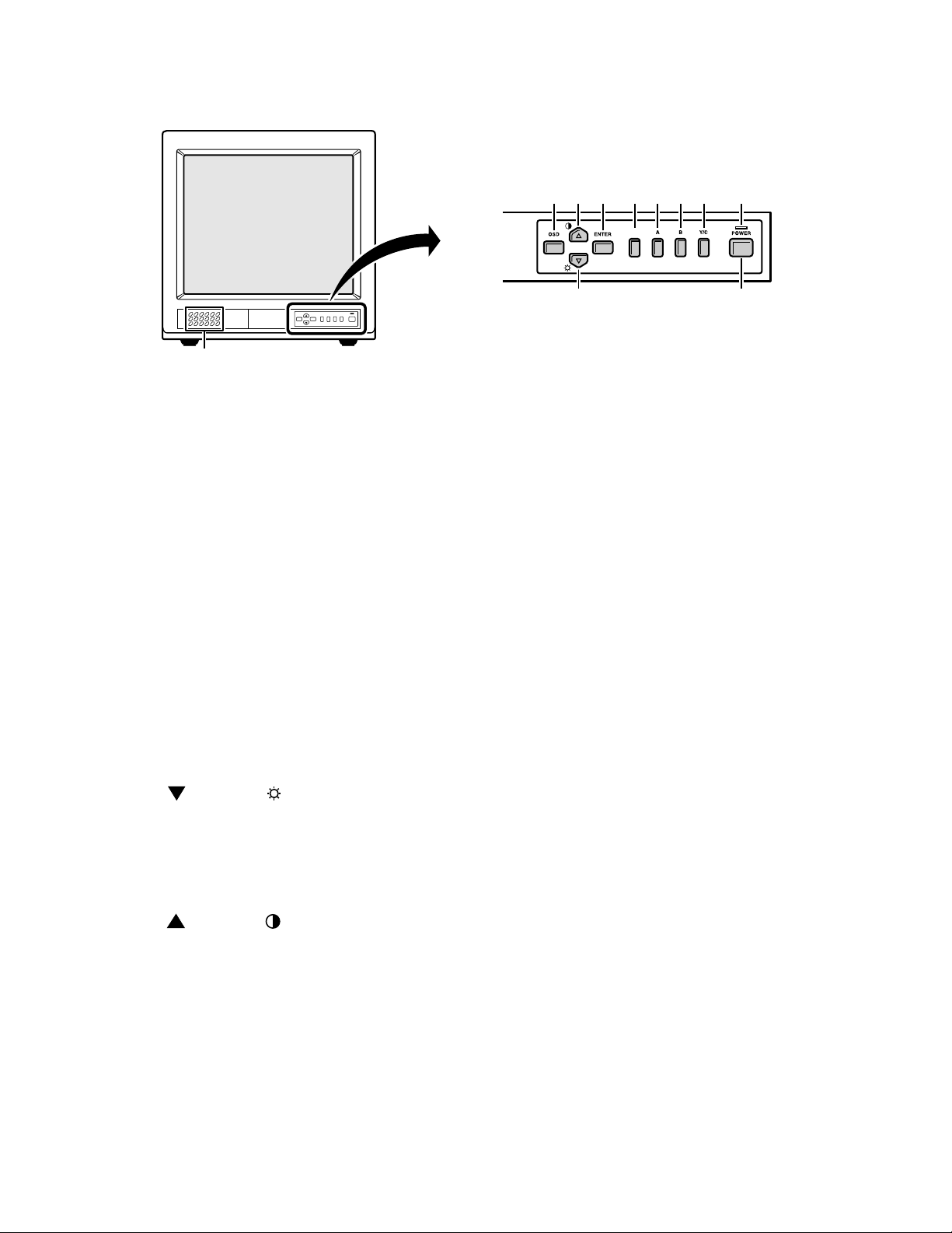
1-1. FRONT PANEL CONTROLS
1
1. Speaker
When the monitor selector button (A, B or Y/C)
is pressed, the speaker lets you hear the sound
from the components which are connected to
the terminals at the rear of the monitor. (Use
components which produce audio output.)
2. On-screen display button (OSD)
When this button is pressed, the menu screen
appears on the monitor screen.
1.COLOR
2.TINT
3.BRIGHTNESS
4.CONTRAST
6.VOLUME
8.LANGUAGE
9.TITLE
10.VERSION
5.SHARPNESS
3. Cursor ( ) button ( )
When this button is pressed, the cursor moves
down. When it reaches the bottom, it reappears
at the top. In addition, this button is used to
make adjustment values smaller.
4. Cursor ( ) button ( )
When this button is pressed, the cursor moves
up. When it reaches the top, it reappears at the
bottom. In addition, this button is used to make
adjustment values larger.
5. Display selector button (ENTER)
If this button is pressed while a picture is on the
monitor screen, the screen changes to the
adjustment screen. If the button is pressed once
more, the picture returns to the previous screen.
245 6
3F
SCAN
7
8
G
9
Fig. 2
6. Underscan/overscan select button (SCAN)
The initial setting is for the normal screen
(overscan). If the SCAN button is pressed, the
screen will become smaller (underscan) than
the normal screen. Change this setting in cases
such as when screen display characters are
missing. If the CSAN button is pressed once
more, the normal screen is display again.
7. Monitor A selector button (A)
When this button is pressed, the audio and
video input changes to the component which is
connected to the A terminals at the rear of the
monitor.
8. Monitor B serector button (B)
When this button is pressed, the audio and
video input changes to the component which is
connected to the B terminals at the rear of the
monitor.
9. Monitor Y/C selector button (Y/C)
When this button is pressed, the audio and
video input changes to the component which is
connected to the Y/C terminals at the rear of the
monitor.
10. Power indicator (POWER)
Lights when the power is on.
11. Power button (POWER)
Press this button to turn the power on and off.
– 4 –
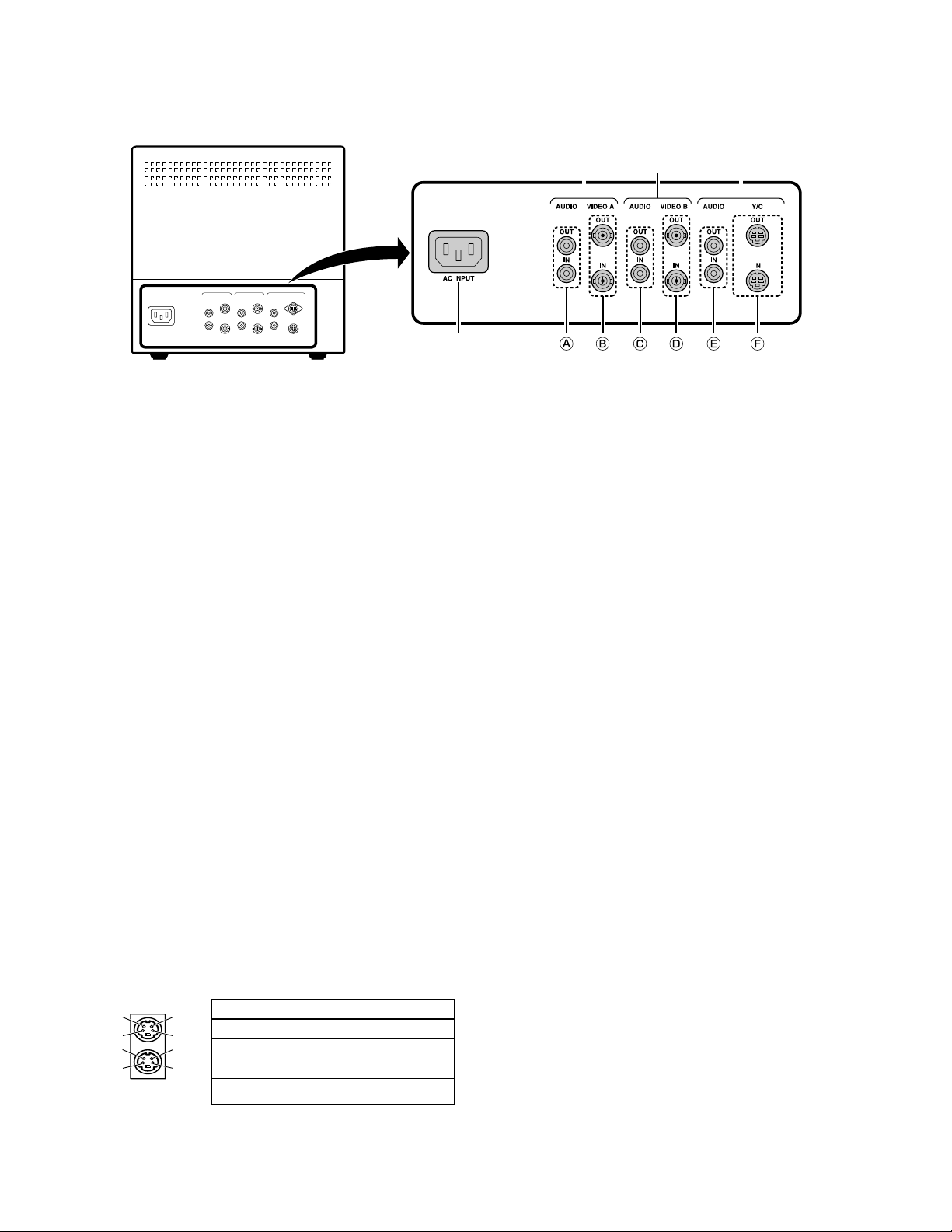
1-2. REAR PANEL CONTROLS & CONNECTION
1
Fig. 3
1. AC INPUT socket
Connect the AC power cord (supplied) securely
to this socket and to a wall outlet.
2. Rear A terminals (AUDIO/VIDEO A terminals)
When the monitor A selector button at the front
of the monitor is pressed, the audio and video
signals from the component which is connected
to these terminals can be monitored.
3. Rear B terminals (AUDIO/VIDEO B terminals)
When the monitor B selector button at the front
of the monitor is pressed, the audio and video
signals from the component which is connected
to these terminals can be monitored.
4. Rear Y/C terminals (AUDIO/VIDEO Y/C
terminals)
When the monitor Y/C selector button at the
front of the monitor is pressed, the audio and
video signals from the component which is
connected to these terminals can be monitored.
23 4
Y/C (Mini DIN 4 pin) terminal specification
OUT
4
2
4
2
3
1
3
1
IN
Pin No. Signal
1 GND (Y)
2 GND (C)
3Y
4C
Fig. 4
– 5 –

2. SERVICE ADJUSTMENTS
1. Supply power to the set and measuring instruments and allow to warm up for at least 30 minutes.
NOTE
Be sure to use a non-metallic driver for adjusting there VRs. A metallic driver can cause damage by shorting.
Adjustment tool
1. Digital multi meter
2. Pattern generator
3. Color analyzer
Adjustment mode
Over scan mode
ADJUSTMENT
ITEM
CHECK B+
VOLTAGE
HOLD DOWN
VOLTAGE
SETTING
FOCUS
ADJUSTMENT
HORIZONTAL
PHASE
ADJUSTMENT
HORIZONTAL
SIZE
ADJUSTMENT
TIMING
PATTERN
PATTERN GENERATOR
MONOSCOPE PATTERN
PATTERN GENERATOR
MONOSCOPE PATTERN
PATTERN GENERATOR
MONOSCOPE PATTERN
PATTERN GENERATOR
MONOSCOPE PATTERN
PATTERN GENERATOR
MONOSCOPE PATTERN
SETTING
BRIGHT VR and
CONTRAST VR
TO MAX.
BRIGHT VR and
CONTRAST VR
TO 75%.
SHARPNESS
VR TO MAX.
BRIGHT VR ,
CONTRAST VR
and SHARPNESS VR TO
MAX.
FACTRY
PRESETTING
VR
LOCATION
VR503
FTB FOCUS
VR1 and VR2
VR401
VR306
ADJUSTMENT PROCEDURE
TEST POINT : D901(-)
DIGITAL VOLT METER
VALUE 38.0 ± 0.5 VDC.
TEST POINT : ZD501(-)
DIGITAL VOLT METER
VALUE 8.35 ± 0.1 VDC.
Adjusting FBT Focus VR1,2 make focus
resolution of reach over 800TV lines, four
corners must be aiso clear.
Adjusting VR401 horizontal phase make
right and left of picture to <=1%.
Adjusting VR306 make signal side of
picture of scale at 1.5 ± 0.5 position.
VERTICAL
LINEARY
ADJUSTMENT
VERTICAL
CENTER
ADJUSTMENT
VERTICAL
SIZE
ADJUSTMENT
PATTERN GENERATOR
MONOSCOPE PATTERN
PATTERN GENERATOR
MONOSCOPE PATTERN
PATTERN GENERATOR
MONOSCOPE PATTERN
BRIGHT VR ,
CONTRAST VR
and SHARPNESS VR TO
MAX.
BRIGHT VR ,
CONTRAST VR
and SHARPNESS VR TO
MAX.
FACTRY
PRESETTING
– 6 –
VR302
VR303
VR301
Adjusting vertical linear control VR302 for
equal spacing of lines between center
extreme of scan [(Max-Min)/Average]<=10%.
Adjusting vertical center control VR303 to
<=1%.
Adjusting vertical size control VR301
make signal side of scale is 1 ± 0.3
position.

ADJUSTMENT
ITEM
WHITE BALANCE ADJUSTMENT
AT VMC-8618
TIMING
PATTERN
PATTERN GENERATOR
NO SIGNAL
SETTING
BRIGHT VR ,
CONTRAST VR
and SHARPNESS
VR TO MAX.
VR
LOCATION
VR801,VR803,
VR805,
FBT FOCUS
VR
ADJUSTMENT PROCEDURE
Adjust VR805 G-Bias to center.
Adjust FBT screen VR make luminance
without video to 1.0 ~ 1.5 FL.
Adjust VR801 make X value is 0.281 ±
0.015.
Adjust VR803 make Y value is 0.298 ±
0.015.
WHITE BALANCE ADJUSTMENT
AT VMC-8619P
LUMINANCE
ADJUSTMENT
PATTERN GENERATOR
FULL WHITE
PATTERN GENERATOR
NO SIGNAL
PATTERN GENERATOR
FULL WHITE
PATTERN GENERATOR
NO SIGNAL
BRIGHT VR ,
CONTRAST VR
and SHARPNESS
VR TO MAX.
BRIGHT VR ,
CONTRAST VR
and SHARPNESS
VR TO MAX.
BRIGHT VR ,
CONTRAST VR
and SHARPNESS
VR TO MAX.
BRIGHT VR ,
CONTRAST VR
and SHARPNESS
VR TO MAX.
VR804,VR802,
VR501
VR801,VR803,
VR805,
FBT FOCUS
VR
VR804,VR802,
VR501
FBT SCREEN
VR
Adjust VR501 make luminance with video
signal to 38 ~ 42 FL.
Adjust VR804 make X value is 0.281 ±
0.015.
Adjust VR802 make Y value is 0.298 ±
0.015.
Adjust VR805 G-Bias to center.
Adjust FBT screen VR make luminance
without video to 1.0 ~ 1.5 FL.
Adjust VR801 make X value is 0.313 ±
0.015.
Adjust VR803 make Y value is 0.329 ±
0.015.
Adjust VR501 make luminance with video
signal to 38 ~ 42 FL.
Adjust VR804 make X value is 0.313 ±
0.015.
Adjust VR802 make Y value is 0.329 ±
0.015.
Adjust FBT screen VR make luminance
without video signal is 1.0 ~ 1.5 FL.
PINCUSHION
ADJUSTMENT
PATTERN GENERATOR
WINDOWS PATTERN
PATTERN GENERATOR
FULL WHITE
PATTERN GENERATOR
CROSSHATCH PATTERN
BRIGHT VR ,
CONTRAST VR
and SHARPNESS
VR TO MAX.
BRIGHT VR ,
CONTRAST VR
and SHARPNESS
VR TO MAX.
BRIGHT VR ,
CONTRAST VR
and SHARPNESS
VR TO MAX.
VR501
VR502
VR305
Adjust VR501 make luminance is 38 ~ 42
FL.
Adjust VR502 make luminance is 85 ± 3
FL.
Then make sure Full White luminance
whether it is 38 ~ 42 FL.
Adjust VR305 make V-Linearity of picture
is in the best condition.
– 7 –

The way of adjusting it which a color analyzer is not used for.
ADJUSTMENT
ITEM
WHITE BALANCE ADJUSTMENT
and
LUMINANCE
ADJUSTMENT
TIMING
PATTERN
PATTERN GENERATOR
NO SIGNAL
PATTERN GENERATOR
FULL WHITE
SETTING
BRIGHT VR ,
CONTRAST VR
and SHARPNESS
VR TO MAX.
BRIGHT VR ,
CONTRAST VR
and SHARPNESS
VR TO MAX.
VR
LOCATION
VR801,VR802,
VR803,VR804,
VR805,
FBT SCREEN
VR
VR804,VR802,
VR501
ADJUSTMENT PROCEDURE
VR801,VR802,VR803,VR804 and VR805
is center position.
Adjust the VR801, VR803 and FBT
SCREEN VR to dark gray with screen.
Adjust the VR802 and VR804 to white
gray with screen.
Adjust the VR501 it makes the screen of
the monitor proper brightness.
– 8 –
 Loading...