

Page 1
INSTRUCTION MANUAL (Pattern sheet attached)
VDC-DP9584S
Color CCD Camera
VDC-DP9584S/VDC-DP9585P VCC-P9574S/VCC-P9575P
Please read this manual before installing and using this
camera, and always follow the instructions in it for proper
use. Be sure to keep it handy for later reference.
• Refer to the supplied CD-ROM for the French, Spanish, German and Chinese
“INSTRUCTION MANUAL”.
To view the INSTRUCTION MANUAL contained in the supplied CD-ROM, you
need Adobe
can download it for installation from the following web site at Adobe Systems
Incorporated.
http://www.adobe.com
• Consultez le CD-ROM fourni pour le « MANUEL D’INSTRUCTIONS » en
français, espagnol, allemand et en chinois.
Pour visualiser le MANUEL D’INSTRUCTIONS contenu dans le CD-ROM
fourni, l’application Adobe
été installé sans cette application, vous pouvez la télécharger depuis le site
Web suivant d’Adobe Systems Incorporated.
http://www.adobe.com
®
Reader® application. If your PC has not been installed with it, you
®
Reader® vous est nécessaire. Si votre ordinateur a
VDC-DP9585P
VCC-P9574S
VCC-P9575P
• Hacer referencia al CD-ROM que se suministra para consultar el “MANUAL DE
INSTRUCCIONES” en francés, español, alemán y chino.
Para ver el MANUAL DE INSTRUCCIONES contenido en el CD-ROM
suministrado, es necesario disponer de la aplicación Adobe
no tiene instalada esta aplicación, es posible descargarla para la instalación en
el siguiente sitio web en Adobe Systems Incorporated.
http://www.adobe.com
• Die “BEDIENUNGSANLEITUNG” in den Sprachen Französich, Spanisch,
Deutsch und Chinesisch finden Sie auf der mitgelieferten CD-ROM.
Zum Öffnen der BEDIENUNGSANLEITUNG auf der mitgelieferten CD-ROM
benötigen Sie das Programm Adobe
auf Ihrem PC installiert ist, können Sie das Programm unter der nachstehend
angegebenen Internet-Adresse bei Adobe Systems Incorporated zur
Installation herunterladen:
http://www.adobe.com
• 请参阅随附的光盘以了解法语、西班牙语、德语和中文 “说明手册”。
要查看随附光盘中包含的说明手册,您需要安装有 Adobe
如果您的PC上没有安装此应用程序,则您可以从
以下网站下载并进行安装。
http://www.adobe.com
®
Reader®. Falls diese Anwendung nicht
®
Reader®. Si el PC
®
Reader®应用程序。
Adobe Systems Incorporated
的
Page 2

Contents
☞The contents in angle brackets < > are the menu screen title.
Getting Started Setting Camera Performance <CAMERA> . . . . . . 14
Precautions . . . . . . . . . . . . . . . . . . . . . . . . . . . . . . . . 3
Information. . . . . . . . . . . . . . . . . . . . . . . . . . . . . . . . . 4
Characteristics . . . . . . . . . . . . . . . . . . . . . . . . . . . . . . . . . . 4
WEEE Symbol Information. . . . . . . . . . . . . . . . . . . . . . . . . 4
Useful Operations . . . . . . . . . . . . . . . . . . . . . . . . . . . . . . . 5
Setting Up and Making Adjustments
Using a Monitor . . . . . . . . . . . . . . . . . . . . . . . . . . . . . 6
Accessing the Main Menu . . . . . . . . . . . . . . . . . . . . 7
Selecting Display Language <LANGUAGE>. . . . . . 9
Naming Cameras <OPTION> – <TITLE> . . . . . . . . . 10
Adjusting Synchronization Error <SYNC> . . . . . . . . . . . . . 15
Backlight Compensation <BLC>. . . . . . . . . . . . . . . . . . . . . 16
Adjusting Iris Level <IRIS> . . . . . . . . . . . . . . . . . . . . . . . . . 17
Setting White Balance <WHITE BALANCE> . . . . . . . . . . . 18
AOne-Push Adjustment (AWC). . . . . . . . . . . . . . . . . . . 19
BManual White Balance (MWB) . . . . . . . . . . . . . . . . . . 20
Setting Gain Value <AGC GAIN>. . . . . . . . . . . . . . . . . . . . 21
Correcting Gamma Characteristic <GAMMA> . . . . . . . . . . 22
Specifying Shutter Speed <SHUTTER>. . . . . . . . . . . . . . . 23
Accentuating Subject Outline <APERTURE>. . . . . . . . . . . 24
(VDC-DP9584S/VDC-DP9585P)
Adjusting DAY/NIGHT Function <DAY/NIGHT>. . . . . . . . . 25
AAdjusting Automatic Setting (AUTO) . . . . . . . . . . . . . 26
BAdjusting Black-and-White Setting (B/W). . . . . . . . . . 27
Setting/Cancelling Password Lock
<PASSWORD> . . . . . . . . . . . . . . . . . . . . . . . . . . . . . . 12
1
Page 3
Contents
Registering Monitoring Positions
<PRESET POSITION> . . . . . . . . . . . . . . . . . . . . . . 28
Automatic Monitoring <AUTO MODE> . . . . . . . . 30
Sequential Panning along the Registered Preset Positions
<SEQUENTIAL PAN> . . . . . . . . . . . . . . . . . . . . . . . . . . . . 31
Automatic Intermittent Panning <AUTO PAN> . . . . . . . . . 32
Hiding Image Partially
<OPTION> – <PRIVACY MASK> . . . . . . . . . . . . . . 42
Configuring the Communication Settings
<OPTION> . . . . . . . . . . . . . . . . . . . . . . . . . . . . . . . . 45
Setting Protocol for Camera Controller <CONTROL> . . . . 45
Setting Camera Address <ADDRESS> . . . . . . . . . . . . . . . 46
Setting Alarm Output to Communication Line
Returning to Specified Monitoring Mode
Automatically <AUTO RETURN> . . . . . . . . . . . . . 34
<ALARM LINE OUT> . . . . . . . . . . . . . . . . . . . . . . . . . . . . . 46
Troubleshooting . . . . . . . . . . . . . . . . . . . . . . . . . . . . 47
Service . . . . . . . . . . . . . . . . . . . . . . . . . . . . . . . . . . . . . . . . 47
Setting Alarm <ALARM>. . . . . . . . . . . . . . . . . . . . 35
Replacement timing of major parts. . . . . . . . . . . . . . . . . . . 47
Specifying Alarm Input <ALARM IN>. . . . . . . . . . . . . . . . . 36
Specifying Alarm Output <ALARM OUT> . . . . . . . . . . . . . 37
Setting Motion Sensor <MOTION> . . . . . . . . . . . . . . . . . . 38
Setting Zooming Up at Alarm Detection <ZOOM>. . . . . . . 40
Setting Alarm Duration <DURATION>. . . . . . . . . . . . . . . . 40
Setting Alarm Detection Notification <ALARM SIGN>. . . . 41
Specifications . . . . . . . . . . . . . . . . . . . . . . . . . . . . . . 48
Pattern sheet
(VDC-DP9584S/VDC-DP9585P)
(VCC-P9574S/VCC-P9575P) . . . . . . . . . . . . . . . . . . . . . . 51
Screen Sequence . . . . . . . . . . . . . . . . . . . . . . . . . . . 53
MEMO:
This instruction manual covers four models. Any difference among the four models is indicated when necessary.
Differences in the menu screen among the four models are as indicated below.
Menu language English/French/Spanish English/French/German
Shutter speed 1/60, 1/100, 1/250, ... 1/50, 1/120, 1/250, ...
Day/Night function m – m –
IP66 m – m –
• This manual describes the menu screen for the VDC-DP9584S.
VDC-DP9584S VCC-P9574S VDC-DP9585P VCC-P9575P
. . . . . . . . . . . . . . . . . . . . 50
2
Page 4

Precautions
■ In case of a problem
Do not use the unit if smoke or a strange odor comes from the unit, or if it
seems not to function correctly. Turn off the power immediately and
disconnect the power cord, and then consult your dealer or an Authorized
Sanyo Service Center.
Getting Started
■ Do not open or modify
Do not open the cabinet, as it may be dangerous and cause damage to
the unit. For repairs, consult your dealer or an Authorized Sanyo Service
Center.
■ Do not put objects inside the unit
Make sure that no metal objects or flammable substance get inside the
unit. If used with a foreign object inside, it could cause a fire, a short-circuit
or damage. Be careful to protect the unit from rain, sea water, etc. If water
or liquid gets inside the unit, turn off the power immediately and disconnect
the power cord, and then consult your dealer or an Authorized Sanyo
Service Center.
■ Be careful when handling the unit
To prevent damage, do not drop the unit or subject it to strong shock or
vibration.
■ Do not install this unit close to magnetic fields
The magnetic fields may result in unstable operation.
■ Protect from humidity and dust
To prevent damage, do not install the unit where there is greasy smoke or
steam, where the humidity may get too high, or where there is a lot of dust.
■ Protect from high temperatures
Do not install close to stoves, or other heat sources, such as spotlights,
etc., or where it could be subject to direct sunlight, as this could cause
deformation, discoloration or other damage.
Be careful when installing close to the ceiling, in a kitchen or boiler room,
as the temperature may rise to high levels.
■ Cleaning
• Dirt can be removed from the cabinet by wiping it with a soft cloth. To
remove stains, wipe with a soft cloth moistened with a soft detergent
solution and wrung dry, then dry by wiping with a soft cloth.
• Do not use benzine, thinner or other chemical products on the cabinet,
as this may cause deformation and paint peeling. Before using a
chemical cloth, make sure to read all accompanying instructions. Make
sure that no plastic or rubber material comes into contact with the
cabinet for a long period of time, as this may cause damage or paint
peeling.
(VDC-DP9584S/VDC-DP9585P)
■ Approvals: IP66
This unit has been certified to IP66 standards when properly installed.
Ensure all openings in enclosure are sealed as per manufacturer's
instructions.
The IP66 has not been verified by UL.
3
Page 5
Information
Characteristics WEEE Symbol Information
• Equipped with motorized zoom pan focus auto iris lens. Thanks to its
large depth of field, focused images can be obtained in a wider range
of scene without intentional focusing.
• Equipped with motorized pan/tilt.
• Can be installed on both the ceiling and walls.
• Configurable preset position (maximum16 positions), sequential pan,
and auto pan.
• Equipped with a motion sensor that detects movement in the monitor
screen and issues an alarm.
• Detects intruders using an external switch or a motion sensor,
automatically zooms in on the images, and notifies using alarm
output.
• If a hard disk recorder is connected, alarm-triggered images can be
recorded according to the alarm output.
• If a hard disk recorder or controller is connected, monitoring and/or
camera adjustment operation can be performed remotely.
• Partial masking can be applied for any part of an image you want to
hide.
• Configurable preference settings with view on screen.
• Access to the main menu is controlled by setting a password.
(VDC-DP9584S/VDC-DP9585P)
• Equipped with function for automatically switching between COLOR
and Black-and-White (DAY/NIGHT).
• Complies with the IP66 international standard for dust and water
protection. (The IP66 has not been verified by UL.)
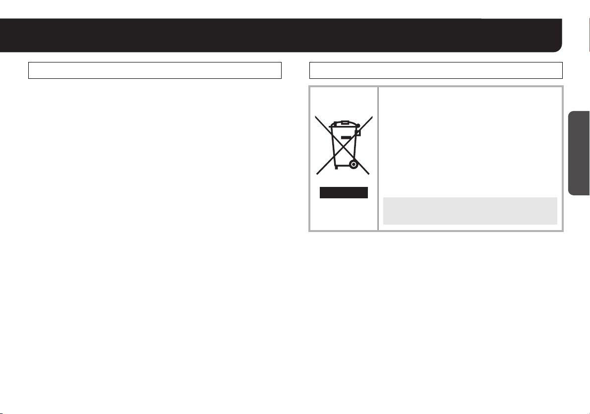
Please note:
Your SANYO product is designed and manufactured with
high quality materials and components which can be
recycled and reused.
This symbol means that electrical and electronic
equipment, at their end-of-life, should be disposed of
separately from your household waste.
Please dispose of this equipment at your local
community waste collection/recycling centre.
In the European Union there are separate collection
systems for used electrical and electronic products.
Please help us to conserve the environment we live in!
This symbol mark and recycle system are
applied only to EU countries and not applied to
the countries in the other area of the world.
Getting Started
4
Page 6

Information
Useful Operations
■ Registering multiple preset positions:
RPRESET POSITION (see page 28)
Getting Started
■ Making the camera move successively along the
registered preset positions:
RAUTO MODE → SEQUENTIAL PAN (see page 31)
■ Performing automatic panning:
RAUTO MODE → AUTO PAN (see page 32)
■ Setting the camera to return to the specified monitoring
mode following manual operation on the angle of view:
RAUTO RETURN (see page 34)
■ Connecting to an external door switch or infrared
sensor:
RALARM (see page 35)
■ Making the unit issue a warning upon detecting
suspicious figures, etc.:
RALARM → MOTION (see page 38)
■ Making the unit record the image at alarm detection:
ROPTION → ALARM LINE OUT (see page 46)
■ Limiting main menu access to administrators:
RPASSWORD (see page 12)
■ Hiding image partially for privacy protection:
ROPTION → PRIVACY MASK (see page 42)
■ Operating remotely using a hard disk recorder or
controller:
ROPTION → CONTROL (see page 45)
(VDC-DP9584S/VDC-DP9585P)
■ Switching between “Color” and “Black-and-White” mode
of DAY/NIGHT function using an external switch, etc.:
RCAMERA → DAY/NIGHT (see page 25)
5
Page 7

Setting Up and Making Adjustments Using a Monitor
■ Using the Camera Control Unit
(VAC-70: Separately ordered)
Camera can be controlled remotely during setting or adjustment.
• Please refer to the instruction manual for VAC-70.
Button operations with VAC-70 are the same as with the unit.
VAC -70
CAMERA
RG-6U (5C-2V) cable,
300 m max.
Example
ADDRESS
CONTROL
BAUD RATE
Video in
1
485S
19200
VIDEO
OUT
BNC type
When the power is turned on, the camera
address (ADDRESS), and protocol
(CONTROL) and baud rate (BAUD RATE)
will be displayed about for 5 seconds on
the monitor screen.
When <PRIVACY MASK> is “ON”,
background of the monitor is shown in
black.
■ Opening the dome cover and setting up the camera
using the buttons on the circuit board
Place the dome cover back once you have finished settings.
• See the INSTALLATION MANUAL supplied with the unit.
Checking the settings screen or
camera angle on a portable monitor
GND
MONITOR
OUT
SET
1
UP
LEFT
2
RIGHT
DOWN
Checking the settings screen or camera angle
1 SET button
Press and hold for about 1 second for the main menu to appear.
2 Select button
• Press up, down, left, right to select an item on the settings screen or change a
setting value.
• The pan/tilt and zoom functions can be operated using the Select button during
live mode (with no settings screen displayed).
Press the SET button to switch over between pan/tilt and zoom operations.
<Pan/Tilt operations>
Pan: Press d(LEFT) or c(RIGHT)
Tilt: Press j(UP) or l(DOWN)
Connect the MONITOR OUT pin and the GND
pin on the circuit board to a monitor using an
alligator clip cable.
(It is also possible to connect a monitor using
the MONITOR OUT connector.)
Note: Do not touch the camera unit except
when settings and adjustments are
necessary.
<Zoom operations>
Wide: Press d(LEFT)
Tel e: Press c(RIGHT)
Getting Started
6
Page 8
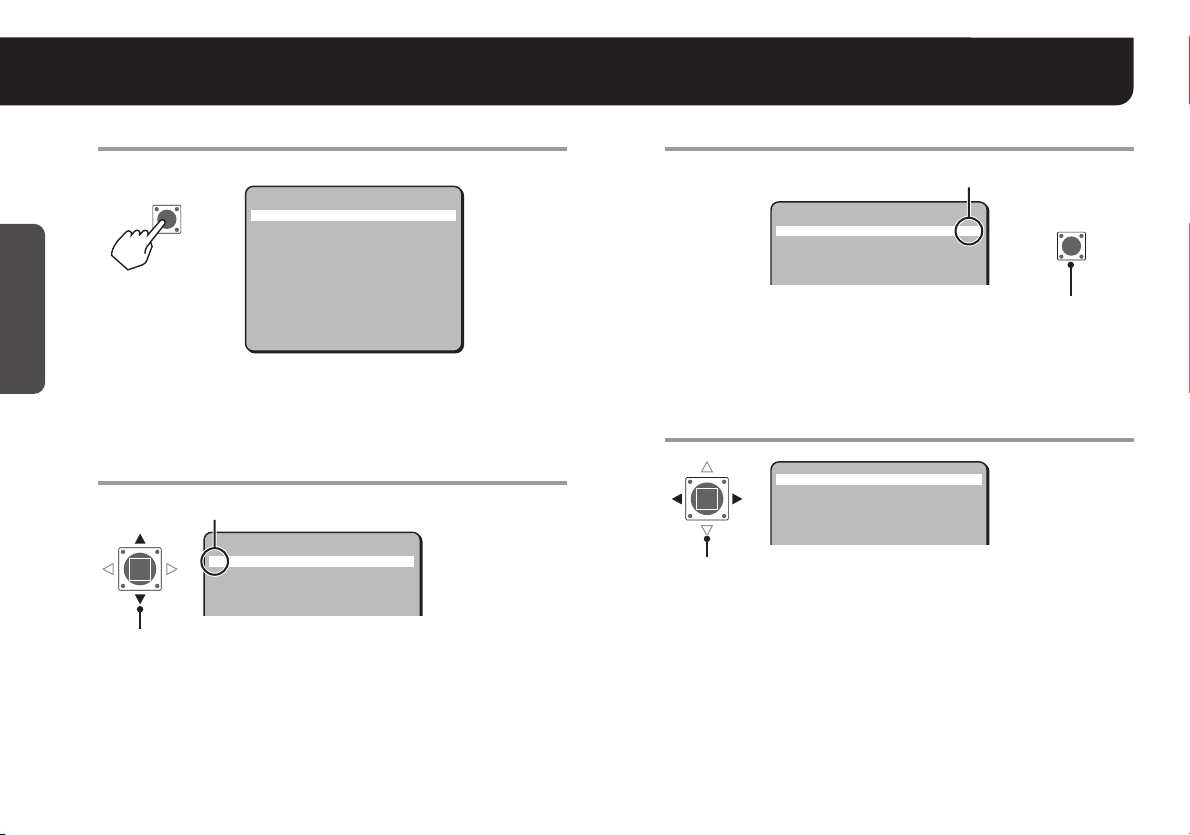
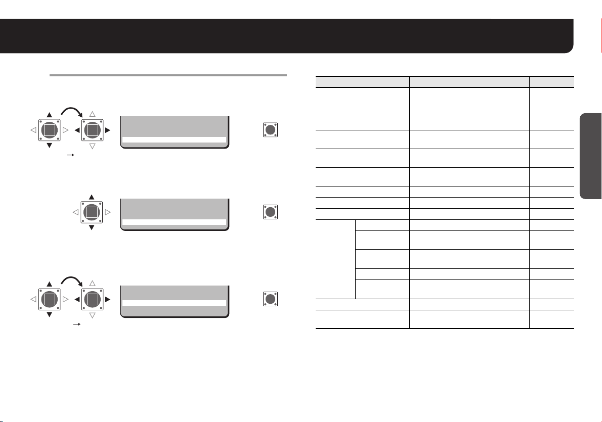
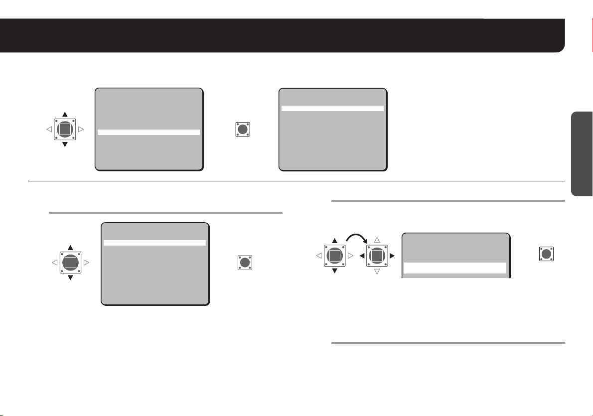
Accessing the Main Menu
Access the main menu.
1
Main menu
SET
Getting Started
R
Press and hold
the button for
about 1 second.
PRESET POSITION
AUTO MODE
AUTO RETURN
ALARM
PASSWORD
LANGUAGE
OPTION
PRESET
MENU
SET y
1 y
SEQ y
OFF
SET y
SET y
SET y
SET y
OFF
END
·CAMERA
Note: After the expiration of a predetermined time interval (3 minutes)
without any operation, the settings screen goes off automatically
and returns to normal monitoring screen.
Select item.
2
Cursor
·CAMERA
PRESET POSITION
AUTO MODE
AUTO RETURN
ALARM
SET y
1 y
SEQ y
OFF
SET y
Moves the cursor “·” using the Select button UP and DOWN
to select the item.
Open the advanced settings screen.
3
When “y” mark displays
·CAMERA
PRESET POSITION
AUTO MODE
AUTO RETURN
ALARM
Specify values.
4
·SYNC
BLC
IRIS
WHITE BALANCE
AGC GAIN
GAMMA
Press the Select button
RIGHT and LEFT to switch
over to other values.
SET y
1 y
SEQ y
OFF
SET y
R
Press the SET button
to open the
advanced settings
screen.
INT
OFF
SET y
ATW
NORM
0.45
SET
7
Page 9
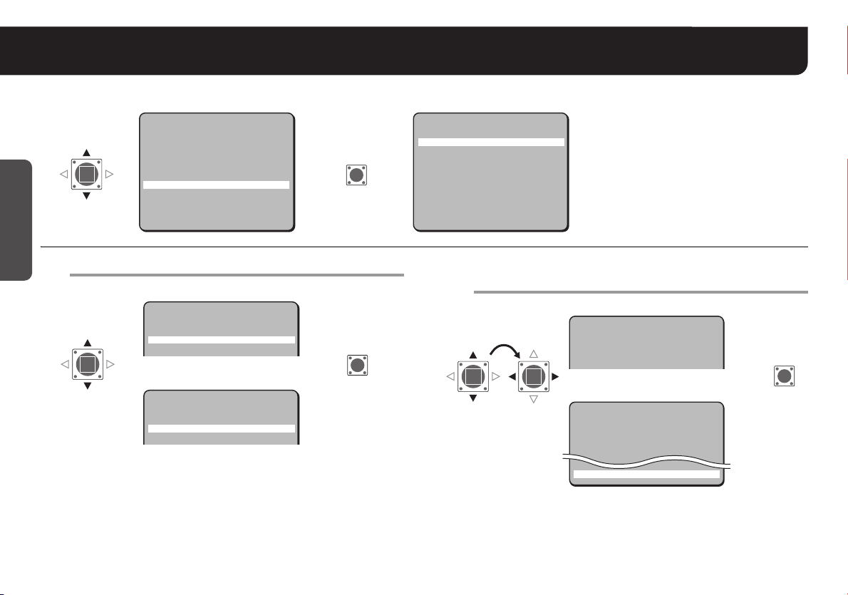
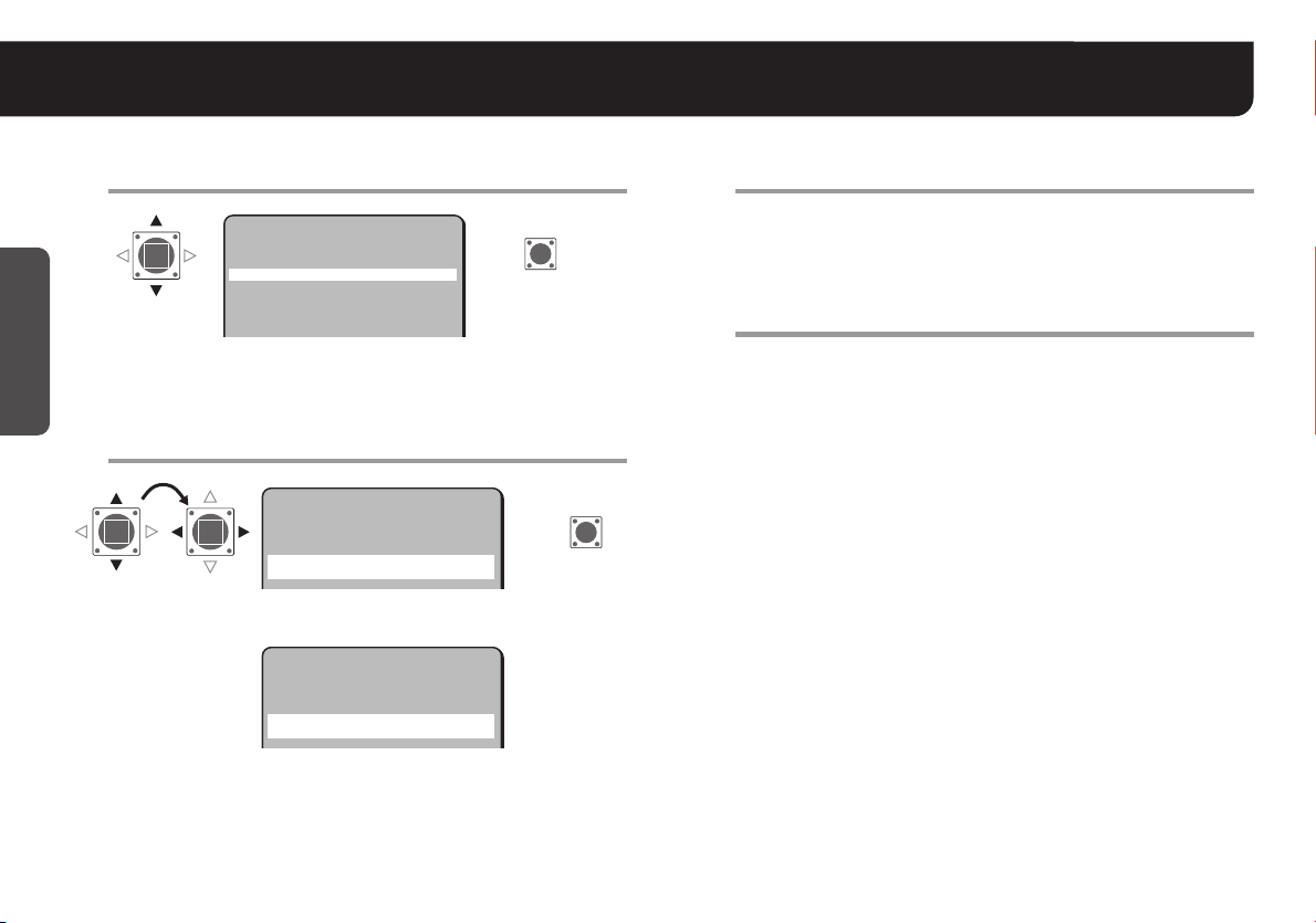
Accessing the Main Menu
Close the settings screen.
5
Once the settings are complete, set <MENU> to “END” and press
the SET button.
SET
PRESET
·MENU
OFF
END
R
·MENU END
■ To return to the previous screen
Select <MENU> – “BACK” and press the SET button.
SET
PRESET
·MENU
OFF
BACK
R
■ To reset settings (Factory Default Settings)
Select <PRESET> and choose “ON” instead of “OFF”, and press the
SET button.
SET
·PRESET
MENU
ON
BACK
·PRESET ON
Note: To reset all the settings, set <PRESET> to “ON” in the main menu
and press the SET button.
The <PRIVACY MASK> and <CONTROL> in <OPTION>, and
<PASSWORD> will not be initialized.
R
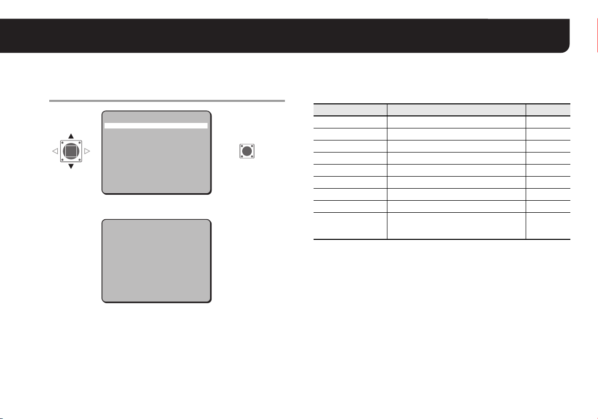
■ Main menu guide
Items Settings See page
Setting Camera Performance
CAMERA
PRESET POSITION
AUTO MO DE
AUTO RETURN
ALARM Setting Alarm 35
PASSWORD Setting/Cancelling Password Lock 12
LANGUAGE Selecting Display Language 9
TITLE Naming Cameras 10
PRIVACY
MASK
OPTION
PRESET Initializing Settings 8
MENU
CONTROL
ADDRESS Setting Camera Address 46
ALARM LINE
OUT
(Synchronization, Backlight
Compensation, Iris Level, White
Balance, Gain, Gamma, Shutter
Speed, Aperture, DAY/NIGHT)
Registering Monitoring Positions
(No.1 - 16)
Automatic Monitoring
(Sequential Pan, Auto Pan)
Returning to Specified Monitoring
Mode Automatically
Hiding Image Partially
Setting Protocol for Camera
Controller
Setting Alarm Output to
Communication Line
Closing a Screen/Returning to
Previous Screen
14
28
30
34
Getting Started
42
45
46
8
8
Page 10
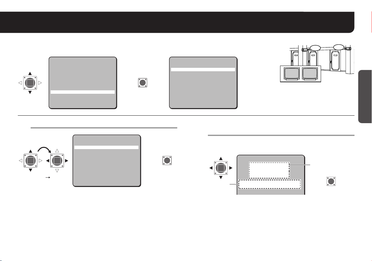
Selecting Display Language <LANGUAGE>
You can change the language displayed on the settings and adjusting screens. (Default setting: English)
Getting Started
CAMERA
PRESET POSITION
AUTO MODE
AUTO RETURN
ALARM
PASSWORD
·LANGUAGE
OPTION
·LANGUAGE
Select a language and press the SET button.
1
PRESET
MENU
SET y
1 y
SEQ y
OFF
SET y
SET y
SET y
SET y
OFF
END
RR
VDC-DP9584S/VCC-P9574S
LANGUAGE
LANGUAGE
·LANGUE
IDIOMA
ENGLISH
FRENCH
SPANISH
R
VDC-DP9585P/VCC-P9575P
LANGUAGE
LANGUAGE
·LANGUE
SPRACHE
ENGLISH
FRENCH
GERMAN
(In case FRENCH is selected)
RPressing the SET button will immediately change the language
displayed on the screen.
For accessing the main menu, see pages 7 – 8.
9
SET
SET
LANGUAGE
·LANGUAGE
LANGUE
IDIOMA
MENU
Set <MENU> to “FIN” (“END”) and press the SET
2
button.
·MENU
RCloses the settings screen and returns to the normal monitoring
screen.
• If you want to return to the previous screen, select “RETOUR”
(“BACK” or “ATRAS”) and press the SET button.
ENGLISH
FRENCH
SPANISH
BACK
FIN
→
(END)
VDC-DP9584S/VCC-P9574S
LANGUE
LANGUAGE ANGLAIS
LANGUE FRANCAIS
IDIOMA ESPAGNOL
VDC-DP9585P/VCC-P9575P
LANGUE
LANGUAGE ANGLAIS
LANGUE FRANCAIS
SPRACHE ALLEMAND
·MENU FIN
(In case FRENCH is selected)
SET
R
Page 11
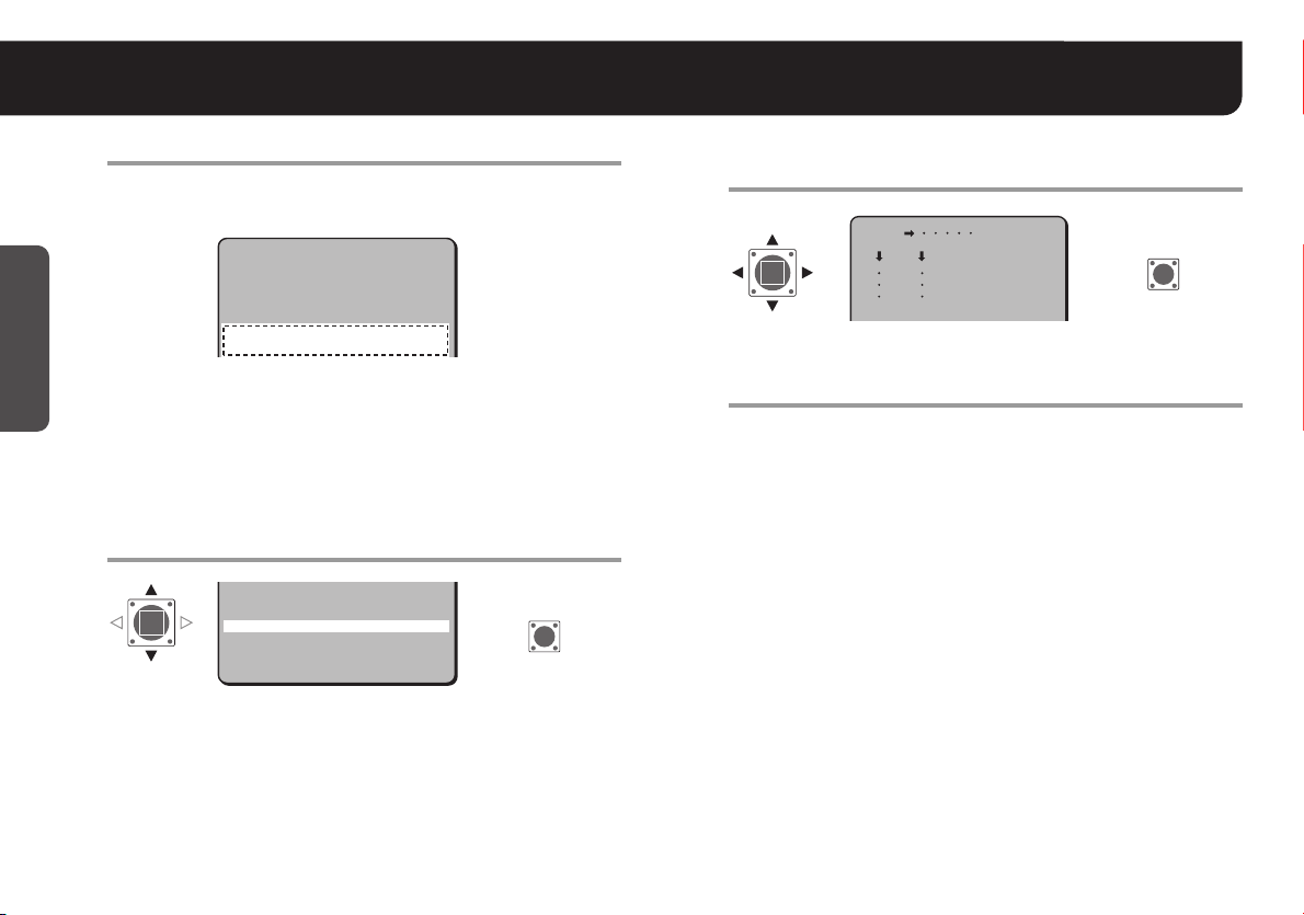
Naming Cameras <OPTION> – <TITLE>
You can give a name (title) to each camera. The specified names are displayed on the monitor
so that you can easily distinguish the monitoring images when you use multiple cameras.
CAMERA
PRESET POSITION
AUTO MODE
AUTO RETURN
ALARM
PASSWORD
LANGUAGE
·OPTION
·OPTION
Set <TITLE> to “ON” and press the SET button.
1
PRESET
MENU
SET y
1 y
SEQ y
OFF
SET y
SET y
SET y
SET y
OFF
END
SET
RR
OPTION
·TITLE
PRIVACY MASK
CONTROL
ADDRESS
ALARM LINE OUT
PRESET
MENU
2
OFF
SET y
COAX
1
OFF
OFF
BACK
Choose a character(s) from the “Character
Selecting Field”.
OPTION
·TITLE
PRIVACY MASK
CONTROL
ADDRESS
ALARM LINE OUT
·TITLE
ON
PRESET
MENU
RThe “TITLE SETTING” screen appears.
ON y
SET y
COAX
1
OFF
OFF
BACK
SET
R
A character is selectable when two arrows, (w) and (y), point at the
character.
TITLE SETTING
y
wABCDEFGHIJKLM
NOPQRSTUVWXYZ
0123456789 :-
ID string
ID ????????????????
x
POSITION
RThe characters are displayed starting from (x) in the “ID string”.
■ To overwrite the character
Select <ID> and move (x) onto it in the “ID string”, and then choose any new
letter.
ROOM1 ROOM2
SET y
ROOM1
ROOM2
Character
Selecting Field
SET
R
Getting Started
For accessing the main menu, see pages 7 – 8.
10
Page 12
Naming Cameras <OPTION> – <TITLE>
Getting Started
Repeat step 2 to complete the name.
3
• You can enter up to 16 characters.
Example: ROOM1
TITLE SETTING
ABCDEFGHIJKLM
NOPQRSTUVWXYZ
0123456789 :-v
·ID ROOM1???????????
x
RThe letters “???....” do not appear on the monitor screen, but if
you select “ON” for the <TITLE> and then enter no letter at all,
the monitor will show you “???....”.
■
If you want the name to be displayed on the monitor in two lines
Select <ID> and enter the line feed mark (v) in the “ID string” wherever you
want to start a new line.
Select <POSITION> and press the SET button.
4
ID ROOM1???????????
x
·POSITION
PRESET
·POSITION
ROn the normal monitoring screen, the name will be displayed.
MENU
SET y
OFF
BACK
SET
R
Determine the location where the name should
5
be displayed, and then press the SET button.
ROOM1
R
RReturns to the settings screen.
Set <MENU> to “END” and press the SET button.
6
RCloses the settings screen and displays the name on the
normal monitoring screen.
• If you want to return to the previous screen, select “BACK” and
press the SET button.
■ To delete the name specified
Set <PRESET> to “ON”, and press the SET button.
RAll the characters in the “ID string” will be displayed with “?”.
MEMO:
• If an alarm signal is input when <ALARM SIGN> is “ON” (see
page 41), the camera name on the screen will blink during the
time set in <DURATION> (see page 40). When the camera name
is not specified, “???....” will blink.
If <MOTION> is “ON” (see page 38), the camera name on the
screen will also blink when the motion sensor detects movement.
• When <PRIVACY MASK> is “ON” (see page 42), the camera
name will not be displayed.
SET
11
Page 13
Setting/Cancelling Password Lock <PASSWORD>
You can lock the access to the main menu by specifying a password. You will be prompted to enter the password to access the
main menu.
CAMERA
PRESET POSITION
AUTO MODE
AUTO RETURN
ALARM
·PASSWORD
LANGUAGE
OPTION
·PASSWORD
Select <PASSWORD LOCK> and press the SET
1
PRESET
MENU
SET y
1 y
SEQ y
OFF
SET y
SET y
SET y
SET y
OFF
END
RR
button.
PASSWORD
·PASSWORD LOCK
PASSWORD CHANGE
·PASSWORD
LOCK
MENU
RThe password input screen appears.
OFF y
SET y
BACK
R
SET
SET
PASSWORD
·PASSWORD LOCK
PASSWORD CHANGE
MENU
Enter the password and press the SET button.
2
When setting a password for the first time, you must enter the
factory default password “1234”.
RYou will see the “OK” message.
Note:
Press the SET button.
3
RDisplays <PASSWORD LOCK> – “ON”.
• “1234” is a factory default password; it is recommended you
• If you want to finish the setting, advance to step 7.
OFF y
SET y
BACK
PASSWORD
R
· 1234
x
If you enter an incorrect password, you will see the “NG” message. If
you fail to enter the valid password three times successively, the
prompt display will disappear. Start again from the beginning.
SET y
change it to your own password. Advance to step 4.
For accessing the main menu, see pages 7 – 8.
Getting Started
SET
12
Page 14
Setting/Cancelling Password Lock <PASSWORD>
Getting Started
Select <PASSWORD CHANGE> and press the
4
SET button.
PASSWORD
PASSWORD LOCK
·PASSWORD CHANGE
·PASSWORD
CHANGE
RThe current password input screen appears.
Enter the current password and press the SET
5
ON y
SET y
R
button.
PASSWORD
<NOW PASSWORD>
· 1234
x
RThe new password input screen appears.
PASSWORD
<NEW PASSWORD>
· ????
x
SET y
SET y
SET
R
SET
Enter a new password (4 numerical values) and
6
press the SET button.
☞ Write down the new password before you forget it.
RYou will see the “OK” message.
Select <MENU> – “END” and press the SET
7
button.
RCloses the settings screen and returns to the normal monitoring
screen.
• If you want to return to the previous screen, select “BACK” and
press the SET button.
■ To cancel the password lock
Press the SET button on <PASSWORD LOCK> – “ON”, and then
enter the password.
RYou will see “OFF” instead of “ON”.
13
Page 15
Setting Camera Performance <CAMERA>
Open the screen for setting and adjusting the camera performance.
Select <CAMERA> and press the SET button.
1
SET y
1 y
SEQ y
OFF
SET y
SET y
SET y
SET y
OFF
END
SET
R
·CAMERA
·CAMERA
PRESET POSITION
AUTO MODE
AUTO RETURN
ALARM
PASSWORD
LANGUAGE
OPTION
PRESET
MENU
RThe settings screen for camera performance appears.
·SYNC
BLC
IRIS
WHITE BALANCE
AGC GAIN
GAMMA
SHUTTER
APERTURE
DAY/NIGHT
PRESET
MENU
INT
OFF
SET y
ATW
NORM
0.45
60
HIGH
AUTO y
OFF
BACK
■ To close the settings screen and return to the normal
monitoring screen
Set <MENU> to “END” and press the SET button.
• If you want to return to the previous screen, select “BACK” and
press the SET button.
■ Camera performance screen guide
Items Settings See page
SYNC Adjusting Synchronization Error 15
BLC Backlight Compensation 16
IRIS Adjusting Iris Level 17
WHITE BALANCE Setting White Balance 18
AGC GAIN Setting Gain Value 21
GAMMA Correcting Gamma Characteristic 22
SHUTTER Specifying Shutter Speed 23
APERTURE Accentuating Subject Outline 24
(VDC-DP9584S/
VDC-DP9585P)
DAY/NIGHT
Adjusting DAY/NIGHT Function 25
For accessing the main menu, see pages 7 – 8.
14
Page 16
Setting Camera Performance <CAMERA>
Adjusting Synchronization Error <SYNC>
By default, the synchronization adjustment for the camera is performed internally (INT). However, you must make adjustments
in the Line-Lock Setting (L-L) screen, if the monitor screen seems out of sync after switching over among multiple cameras
using AC 24 V. Select a camera as a reference and adjust the others based on the selected one.
Note: The Line-Lock setting is not available for DC 12 V operation.
Set <SYNC> to “L-L” and press the SET button.
1
L-L y
OFF
SET y
ATW
NORM
0.45
60
HIGH
AUTO y
OFF
BACK
·SYNC L-L
Lamp
·SYNC
BLC
IRIS
WHITE BALANCE
AGC GAIN
GAMMA
SHUTTER
APERTURE
DAY/NIGHT
PRESET
MENU
RThe “L-L SETTING” screen appears.
Adjust synchronization (0 – 524).
2
L-L SETTING
<V SYNC PHASE>
· 250
• Make adjustments so that the vertical synchronization of the
monitor screen does not move up or down.
For accessing the main menu, see pages 7 – 8.
15
R
SET
■ INT
Internally synchronized
• Lamp turned on.
■ L-L (Line-Lock)
Synchronizes the unit with power frequency
• Lamp blinking.
Select <MENU> – “BACK” and press the SET
3
button.
RReturns to the camera performance screen.
• If you want to close the settings screen, set to “END” and press
the SET button.
Page 17
Setting Camera Performance <CAMERA>
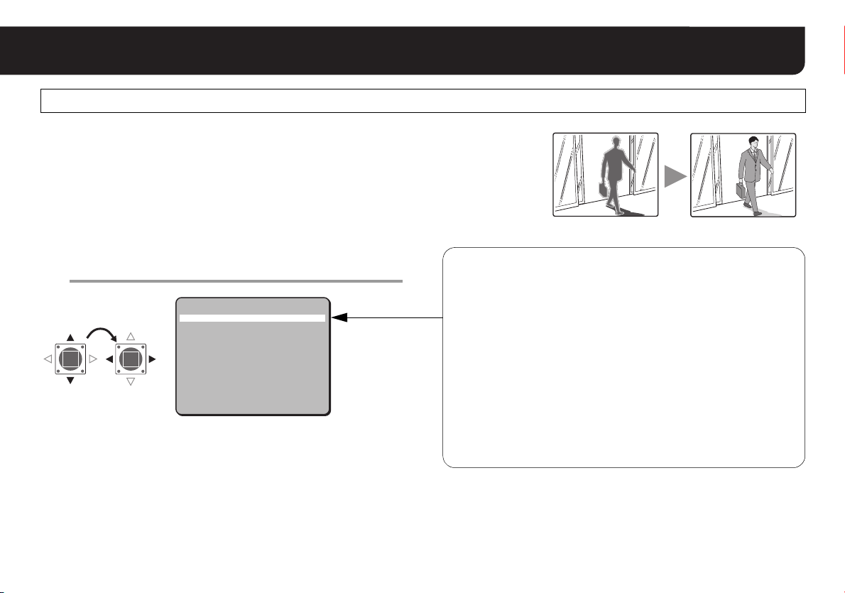
Backlight Compensation <BLC>
If the images of subjects are not clear because of backlight, compensate for it by
adjusting conditions or changing the compensation method.
Select <BLC> and specify the compensation
1
method.
SYNC
·BLC
IRIS
WHITE BALANCE
AGC GAIN
GAMMA
SHUTTER
APERTURE
DAY/NIGHT
·BLC
PRESET
MENU
■ If you want to return to the previous screen
Select <MENU> – “BACK” and press the SET button.
■ If you want to close the settings screen
Set <MENU> to “END” and press the SET button.
INT
OFF
SET y
ATW
NORM
0.45
60
HIGH
AUTO y
OFF
BACK
■ CENT (Center zone metering)
Compensation is made based on the optical measurement that is
focused on the central area of the screen (the image of subject to
be compensated is located in the center of the screen).
■ MULT1 (Multi-spot metering, Normal mode)
Compensation is made based on the optical measurement and
assessment of the entire screen (the image of subject to be
compensated is not limited to a center of the screen location).
■ MULT2 (Multi-spot metering, High mode)
Compared to MULT1, faster backlight compensation is possible
against a lesser amount of light.
■ OFF
No compensation is performed for backlight.
For accessing the main menu, see pages 7 – 8.
16
Page 18

Setting Camera Performance <CAMERA>
Adjusting Iris Level <IRIS>
If you need to adjust the brightness, follow the steps below.
Select <IRIS> and press the SET button.
1
INT
OFF
SET y
ATW
NORM
0.45
60
HIGH
AUTO y
OFF
BACK
·IRIS
SYNC
BLC
·IRIS
WHITE BALANCE
AGC GAIN
GAMMA
SHUTTER
APERTURE
DAY/NIGHT
PRESET
MENU
RThe “IRIS SETTING” screen appears.
Adjust the brightness (iris) (0 – 100).
2
IRIS SETTING
<LEVEL>
· 20
PRESET
MENU
OFF
BACK
• The greater the number, the brighter it gets.
For accessing the main menu, see pages 7 – 8.
17
R
SET
Select <MENU> – “BACK” and press the SET
3
button.
RReturns to the camera performance screen.
• If you want to close the settings screen, set to “END” and press
the SET button.
• Under extremely bright lighting, unfavorable phenomena may
Note:
occur such as swaths of smear on the screen, because light
intensity entering the lens is too high to be controlled. Reduce the
intensity by changing the angle of the lighting source or by other
means.
• If the images of subjects under fluorescent lighting are flickering,
replace fluorescent lighting with incandescent lighting.
Page 19

Setting Camera Performance <CAMERA>
Setting White Balance <WHITE BALANCE>
With its default Auto-Tracing White Balance (ATW) setting, this unit is able to obtain natural colors even when the light source
is changed. However, you may manually change the white balance settings or its mode to obtain better tone, especially when
the screen color does not match actual objects.
Select <WHITE BALANCE> and specify a mode.
1
SYNC
BLC
IRIS
·WHITE BALANCE
AGC GAIN
GAMMA
SHUTTER
APERTURE
DAY/NIGHT
·WHITE
BALANCE
For advanced settings (AWC or MWB), press the
2
PRESET
MENU
SET button.
REach corresponding settings screen will appear.
• Advances to A on next page when selecting “AWC”.
Advances to B on page 20 when selecting “MWB”.
■ If you want to return to the previous screen
Select <MENU> – “BACK” and press the SET button.
■ If you want to close the settings screen
Set <MENU> to “END” and press the SET button.
INT
OFF
SET y
ATW
NORM
0.45
60
HIGH
AUTO y
OFF
BACK
■ ATW (Auto-Tracing White Balance)
Automatic setting for white balance.
■ AWC (One-Push Adjustment): (see next page)
Adjusts white balance by shooting white paper or wall.
■ 3200 (Halogen light or incandescent lamp, etc.)
(fixed)
Targeted at around 3200 K of color temperature.
■ 5600 (Daytime sunlight) (fixed)
Targeted at around 5600 K of color temperature.
■ FLUO (Fluorescent lamp) (fixed)
Targeted at around 4200 K of color temperature.
■ MWB (Manual White Balance): (see page 20)
Fine-adjusts red and blue manually.
For accessing the main menu, see pages 7 – 8.
18
Page 20

Setting Camera Performance <CAMERA>
A One-Push Adjustment (AWC)
Select <AWC LOCK>.
1
AWC SETTING
·AWC LOCK
GO TO MWB
·AWC LOCK
Point a camera to a white paper or wall to project
2
SET
SET y
an image on the whole screen, and press the SET
button.
White paper or wall
SET
RThe cursor “q” lights off, and white balance adjustment will
start. The adjustment will end after about 2 seconds when “q”
lights again.
• If the adjustment does not yield a satisfactory result, press the
SET button again.
■ To perform fine adjustment of color
In the “AWC SETTING” screen, select <GO TO MWB> – “SET”, and
press the SET button.
RThe “MWB SETTING” screen appears. Specify values manually
(see next page).
MEMO: Transferring to the “MWB SETTING” screen through <GO
TO MWB>, white balance mode (see page 18) will be
changed to “MWB”.
Select <MENU> – “BACK” and press the SET
3
button.
RReturns to the camera performance screen.
• If you want to close the settings screen, set to “END” and press
the SET button.
19
Page 21

B Manual White Balance (MWB)
Setting Camera Performance <CAMERA>
Select <R> or <B> to adjust tint (0 – 255).
1
MWB SETTING
· R 43
B 66
PRESET
MENU
R : Adjusting Red
B : Adjusting Blue
• The greater the number, the deeper the tint becomes.
OFF
BACK
Select <MENU> – “BACK” and press the SET
2
button.
RReturns to the camera performance screen.
• If you want to close the settings screen, set to “END” and press
the SET button.
20
Page 22

Setting Camera Performance <CAMERA>
Setting Gain Value <AGC GAIN>
If you need to adjust the sensitivity in dark places (AGC*), follow the steps below.
Select <AGC GAIN> and specify a mode.
1
INT
OFF
SET y
ATW
NORM
0.45
60
HIGH
AUTO y
OFF
BACK
·AGC GAIN
SYNC
BLC
IRIS
WHITE BALANCE
·AGC GAIN
GAMMA
SHUTTER
APERTURE
DAY/NIGHT
PRESET
MENU
■ If you want to return to the previous screen
Select <MENU> – “BACK” and press the SET button.
■ If you want to close the settings screen
Set <MENU> to “END” and press the SET button.
*AGC (Auto Gain Control) is a function to adjust automatically the
gain of the Video signal from the camera so that an optimum signal
level is obtained according to brightness of the object.
For accessing the main menu, see pages 7 – 8.
21
■ NORM
Normal setting
■ HIGH (For a dark subject)
Setting with which a bright image is obtained in a lower
illuminance than the NORM setting.
• This setting causes noise generation and a grainy image.
■ OFF
Fixed gain setting
Page 23

Correcting Gamma Characteristic <GAMMA>
Change the mode for Gamma correction*.
Select <GAMMA> and specify a mode.
1
Setting Camera Performance <CAMERA>
INT
OFF
SET y
ATW
NORM
0.45
60
HIGH
AUTO y
OFF
BACK
·GAMMA
SYNC
BLC
IRIS
WHITE BALANCE
AGC GAIN
·GAMMA
SHUTTER
APERTURE
DAY/NIGHT
PRESET
MENU
■ If you want to return to the previous screen
Select <MENU> – “BACK” and press the SET button.
■ If you want to close the settings screen
Set <MENU> to “END” and press the SET button.
* About Gamma correction
Gamma (γ) is a value representing a responsiveness characteristic of
image contrast. Every input and output device of image data has its
own Gamma value; the overall Gamma value must be corrected to be
equal to 1. If a CRT monitor has a Gamma value of 2.2, for example,
the value for this unit must be corrected to 0.45 (2.2 x 0.45 ≈ 1).
■ 0.45
Gamma value of γ = 0.45
■ 1
Gamma value of γ = 1
For accessing the main menu, see pages 7 – 8.
22
Page 24

Setting Camera Performance <CAMERA>
Specifying Shutter Speed <SHUTTER>
You can specify the electronic shutter speed to capture fast-moving subjects.
Note: With the increase in shutter speed number, faster movement can be captured, though the image becomes darker.
Select <SHUTTER> and specify a shutter speed.
1
INT
OFF
SET y
ATW
NORM
0.45
60
HIGH
AUTO y
OFF
BACK
·SHUTTER
SYNC
BLC
IRIS
WHITE BALANCE
AGC GAIN
GAMMA
·SHUTTER
APERTURE
DAY/NIGHT
PRESET
MENU
(VDC-DP9584S/VCC-P9574S)
• Select from: 60, 100, 250, 500, 1000, 2000, 4000 and 10000
(e.g., 60 refers to 1/60 second)
(VDC-DP9585P/VCC-P9575P)
• Select from: 50, 120, 250, 500, 1000, 2000, 4000 and 10000
(e.g., 50 refers to 1/50 second)
For accessing the main menu, see pages 7 – 8.
23
■ If you want to return to the previous screen
Select <MENU> – “BACK” and press the SET button.
■ If you want to close the settings screen
Set <MENU> to “END” and press the SET button.
Page 25

Setting Camera Performance <CAMERA>
Accentuating Subject Outline <APERTURE>
By specifying the APERTURE* setting, you can accentuate the outline of the subject when its image is blurred and
unidentifiable.
Select <APERTURE> and specify a mode.
1
SYNC
BLC
IRIS
WHITE BALANCE
AGC GAIN
GAMMA
SHUTTER
·APERTURE
·APERTURE
■ If you want to return to the previous screen
Select <MENU> – “BACK” and press the SET button.
■ If you want to close the settings screen
Set <MENU> to “END” and press the SET button.
DAY/NIGHT
PRESET
MENU
INT
OFF
SET y
ATW
NORM
0.45
60
HIGH
AUTO y
OFF
END
■ OFF
No accentuating is performed for aperture.
■ NORM
Normal setting
■ HIGH
Setting with which the outline becomes crisper than the
NORM setting.
■ HIpls (High plus)
Setting with which the outline becomes crisper than the HIGH
setting.
* Aperture means outline correction. The more the outline is
highlighted, the higher the apparent resolution looks.
For accessing the main menu, see pages 7 – 8.
24
Page 26

Setting Camera Performance <CAMERA>
Adjusting DAY/NIGHT Function <DAY/NIGHT> : (VDC-DP9584S/VDC-DP9585P)
The DAY/NIGHT function automatically switches over between COLOR and B/W mode
depending on the ambient brightness. As appropriate for any specific environment, you
can fix the mode to either COLOR or B/W, and adjust the way the switching function works.
Select <DAY/NIGHT> and specify a mode.
1
SYNC
BLC
IRIS
WHITE BALANCE
AGC GAIN
GAMMA
SHUTTER
APERTURE
·DAY/NIGHT
·DAY/NIGHT
PRESET
MENU
RImage switches immediately after the selection is made.
During the switching operation, you may hear switch-over noise
Note:
inside the camera or see a distorted picture, but these are not signs
of trouble.
For advanced settings (“AUTO” or “B/W”), press
2
the SET button.
INT
OFF
SET y
ATW
NORM
0.45
60
HIGH
AUTO y
OFF
BACK
■ AUTO: (see next page)
Automatically switches between COLOR and B/W mode
depending on the ambient brightness (DAY/NIGHT function).
■ COLOR
Color image on a steady basis; suitable for always bright
location or conditions.
■ B/W (Black-and-White): (see page 27)
B/W image on a steady basis; suitable when sensitivity is
prioritized.
■ If you want to return to the previous screen
Select <MENU> – “BACK” and press the SET button.
■ If you want to close the settings screen
Set <MENU> to “END” and press the SET button.
REach corresponding settings screen will appear.
• Advances to A on next page when selecting “AUTO”.
Advances to B on page 27 when selecting “B/W”.
For accessing the main menu, see pages 7 – 8.
25
Page 27

A Adjusting Automatic Setting (AUTO)
B/W
Color
B/W
Color
Select <LEVEL> and specify a level for
1
DAY/NIGHT switching.
Setting Camera Performance <CAMERA>
Select <MENU> – “BACK” and press the SET
3
button.
DAY/NIGHT SETTING
·LEVEL
BURST
·LEVEL
B/W
B/W ColorB/W
B/W Color
LOW HIGH
LOW : Switches in darker conditions.
HIGH : Switches in brighter conditions.
Set <BURST> to “ON” or “OFF” for the burst
2
Color
Color
LOW
OFF
signal*.
DAY/NIGHT SETTING
LEVEL
·BURST
·BURST
ON : Burst signal inserted into the Black-and-White image.
• Inserting the burst signal prevents the image distortion that may
OFF : Burst signal not inserted into the Black-and-White image.
occur when switching from Color to Black-and-White.
LOW
OFF
RReturns to the camera performance screen.
• If you want to close the settings screen, set to “END” and press
the SET button.
• If an infrared lighting system is used, the B/W mode may switch
Note:
* The burst signals are color synchronization signals required for
reproducing color.
to COLOR when a subject reflects the light intensely. Place the
unit out of the infrared lighted area.
• When <MOTION> is “ON” (see page 38), the motion sensor
detection will be interrupted during switching over from B/W to
COLOR mode and from COLOR to B/W mode.
26
Page 28

Setting Camera Performance <CAMERA>
B Adjusting Black-and-White Setting (B/W)
Set <BURST> to “ON” or “OFF” for the burst
1
signal*.
DAY/NIGHT SETTING
·BURST
·BURST
ON : Burst signal inserted into the Black-and-White image.
• Inserting the burst signal prevents the image distortion that may
occur when switching from Color to Black-and-White.
OFF : Burst signal not inserted into the Black-and-White image.
* The burst signals are color synchronization signals required for
reproducing color.
PRESET
MENU
OFF
OFF
BACK
Select <MENU> – “BACK” and press the SET
2
button.
RReturns to the camera performance screen.
• If you want to close the settings screen, set to “END” and press
the SET button.
27
Page 29

Registering Monitoring Positions <PRESET POSITION>
You can register the position information of a camera such as its angle or zoom (maximum 16 positions).
You can change the monitoring angle easily as required.
Select the <PRESET POSITION> number (No. 1 –
1
16) to register and press the SET button.
CAMERA
·PRESET POSITION
AUTO MODE
AUTO RETURN
ALARM
·PRESET
POSITION
RThe “PRESET NO.” screen appears.
Set <PRESET POSITION> to “ON” and press the
2
PASSWORD
LANGUAGE
OPTION
SET y
1 y
SEQ y
OFF
SET y
SET y
SET y
SET y
SET button.
PRESET NO.1
·PRESET POSITION
PRESET ID
SKIP
·PRESET
POSITION
RThe “PAN/TILT” screen appears.
• “PRESET NO.1” cannot be turned OFF.
ON
ON y
OFF
OFF
R
R
SET
SET
Set angle with the Select button and press the
3
SET button.
Tilt
Pan Pan
Tilt
Pan, tilt, and zoom settings are performed on the same screen during
MEMO:
remote operation through a hard disk recorder or controller.
Press the SET button to switch over between pan/tilt and zoom
operations.
Set zoom with the Select button and press the
4
PAN/TILT
SET button.
ZOOM
Wide Tele
RReturns to the “PRESET NO.” screen.
SET
R
SET
R
For accessing the main menu, see pages 7 – 8.
28
Page 30

Registering Monitoring Positions <PRESET POSITION>
For showing the PRESET number during
5
monitoring, set <PRESET ID> to “ON”.
PRESET NO.1
PRESET POSITION
·PRESET ID
SKIP
·PRESET ID
For skipping the preset position during
6
ON
ON y
ON
OFF
sequential panning, set <SKIP> to “ON”.
PRESET NO.1
·SKIP ON
PRESET POSITION
PRESET ID
·SKIP
ON y
ON
ON
■ To cancel a registered preset position
Change <PRESET POSITION> - “ON” to “OFF”. The registered
position information can be restored by returning the setting to “ON”.
“PRESET NO.1” cannot be turned OFF.
Note:
■ To change registered preset position information
Repeat steps from 1 to 6.
Set <MENU> to “END” and press the SET button.
7
RCloses the settings screen and returns to the normal monitoring
screen.
• If you want to return to the previous screen, select “BACK” and
press the SET button.
29
Page 31

Automatic Monitoring <AUTO MODE>
You can make the camera move successively along the registered preset positions or pan automatically during monitoring.
Select <AUTO MODE> and specify a mode.
1
CAMERA
PRESET POSITION
·AUTO MODE
AUTO RETURN
ALARM
PASSWORD
LANGUAGE
OPTION
·AUTO MODE
For advanced settings, press the SET button.
2
PRESET
MENU
RAdvances to next page when selecting “SEQ”.
Advances to page 32 when selecting “PAN”.
SET y
1 y
SEQ y
OFF
SET y
SET y
SET y
SET y
OFF
END
■ SEQ (Sequential Pan) (see next page)
Sequential panning along the registered preset positions
■ PAN (Auto Pan) (see page 32)
Automatic intermittent panning
For accessing the main menu, see pages 7 – 8.
30
Page 32

Automatic Monitoring <AUTO MODE>
Sequential Panning along the Registered Preset Positions <SEQUENTIAL PAN>
Note: You need 2 or more positions registered for preset positions (No. 1 - 16).
Select <ORDER> and set the panning sequence.
1
SEQUENTIAL PAN
·ORDER
PAUSE TIME
SPEED
·ORDER
STEP
RANDOM
Select <PAUSE TIME> and set the time to remain
2
: Pans in ascending order of registered PRESET NOs.
: Pans in random order of registered PRESET NOs.
RUN
STEP
5S
NORM
SET
at the preset position.
SEQUENTIAL PAN
ORDER
·PAUSE TIME
SPEED
·PAUSE TIME
RUN
• Select from: 5S, 10S, 15S, 20S, 30S, 45S, 60S (S=second)
STEP
5S
NORM
SET
Select <SPEED> and set the transfer speed
3
between the preset positions.
SEQUENTIAL PAN
ORDER
PAUSE TIME
·SPEED
·SPEED
: Slower than NORM
SLOW
: Default setting
NORM
: Faster than NORM
FAS T
Select <RUN> and press the SET button to
4
RUN
STEP
5S
NORM
SET
perform a sequential pan.
SEQUENTIAL PAN
ORDER
PAUSE TIME
SPEED
·RUN
Set <MENU> to “END” and press the SET button.
5
·RUN
RThe sequential panning starts.
■ To cancel a sequential pan
Press the Select or SET button.
STEP
5S
NORM
SET
SET
R
31
Page 33

Automatic Intermittent Panning <AUTO PAN>
Automatic Monitoring <AUTO MODE>
Set <POSITION> to “START” and press the SET
1
button.
AUTO PAN
·POSITION
PAUSE TIME
SPEED
·POSITION START
RUN
RThe “PAN/TILT” screen appears.
■ Set the starting position for the automatic pan
Tilt
Pan Pan
Tilt
Pan, tilt, and zoom settings are performed on the same screen during
MEMO:
remote operation through a hard disk recorder or controller.
Press the SET button to switch over between pan/tilt and zoom
operations.
Wide Tele
RReturns to the “AUTO PAN” screen.
PAN/TILT
ZOOM
STARTy
5S
NORM
SET
R
R
R
SET
SET
SET
Set <POSITION> to “END” and press the SET
2
button.
AUTO PAN
·POSITION
PAUSE TIME
SPEED
·POSITION END
RUN
RThe “PAN” screen appears.
■ Set the end position for the automatic pan
PAN
Pan Pan
RReturns to the “AUTO PAN” screen.
END y
5S
NORM
SET
SET
R
SET
R
32
Page 34

Automatic Monitoring <AUTO MODE>
Select <PAUSE TIME> and set the time to stop at
3
the starting position and the end one.
AUTO PAN
·PAUSE TIME
POSITION
·PAUSE TIME
SPEED
RUN
STARTy
5S
NORM
SET
• Select from: 5S, 10S, 15S, 20S, 30S, 45S, 60S (S=second)
Select <SPEED> and set the transfer speed
4
between the preset positions.
AUTO PAN
·SPEED
SLOW
NORM
FAS T
POSITION
PAUSE TIME
·SPEED
RUN
: Slower than NORM
: Default setting
: Faster than NORM
STARTy
5S
NORM
SET
Select <RUN> and press the SET button to
5
perform an automatic pan.
AUTO PAN
POSITION
PAUSE TIME
SPEED
·RUN
·RUN
RThe auto panning starts.
■ To cancel an auto pan
Press the Select or SET button.
STARTy
5S
NORM
SET
SET
R
33
Page 35

Returning to Specified Monitoring Mode Automatically <AUTO RETURN>
Performing a manual operation on the angle of view (pan, tilt, or zoom) cancels the current monitoring mode (sequential pan,
auto pan, preset position). However, you can set the camera to return to the specified monitoring mode automatically once the
manual operation is over.
Set <AUTO RETURN> to “ON” and press the SET
1
button.
CAMERA
PRESET POSITION
AUTO MODE
·AUTO RETURN
ALARM
PASSWORD
·AUTO RETURN
ON
LANGUAGE
OPTION
RThe “AUTO RETURN” screen appears.
Select <MODE> to specify the monitoring mode
2
SET y
1 y
SEQ y
ON y
SET y
SET y
SET y
SET y
for auto return.
AUTO RETURN
·MODE
SEQ
PAN
PRE 1 – 16
·MODE
TIME
: Returns to sequential panning.
: Returns to automatic panning.
: Returns to the registered preset position (PRESET
NO. 1 - 16).
SEQ
1M
R
SET
Select <TIME> to set the timing to return to the
3
specified monitoring mode.
AUTO RETURN
MODE
·TIME
·TIME
PRESET
MENU
• Select from: 10S, 20S, 30S, 40S, 50S, 1M, 2M, 3M, 4M, 5M,
6M, 7M, 8M, 9M, 10M (S=second, M=minute)
<TIME> specifies the pause after manual operation.
Note:
Set <MENU> to “END” and press the SET button.
4
RCloses the settings screen and returns to the normal monitoring
screen.
• If you want to return to the previous screen, select “BACK” and
press the SET button.
For accessing the main menu, see pages 7 – 8.
SEQ
1M
OFF
BACK
34
Page 36

Setting Alarm <ALARM>
If you have connected an external door switch or an infrared sensor, specify the following settings. You may set up two
channels for external alarm input. This unit has a built-in motion sensor, which outputs alarm signals when any moving
subject, such as a would be intruder, is detected.
If you connect external buzzers and/or lamps, alarm signals will also be output to them at alarm detection for you to have
audible and/or visual notifications.
Select <ALARM> and press the SET button.
1
SET y
1 y
SEQ y
OFF
SET y
SET y
SET y
SET y
OFF
END
·ALARM
CAMERA
PRESET POSITION
AUTO MODE
AUTO RETURN
·ALARM
PASSWORD
LANGUAGE
OPTION
PRESET
MENU
RThe “ALARM SETTING” screen appears.
ALARM SETTING
·ALARM IN
ALARM OUT
MOTION
uAREA
uSENSITIVITY
ZOOM
uZOOM TIME
DURATION
ALARM SIGN
PRESET
MENU
For accessing the main menu, see pages 7 – 8.
35
1 y
NO
OFF
SET y
SET y
OFF
5S
5S
OFF
OFF
BACK
R
SET
■ Alarm setting guide
Items Settings See page
ALARM IN Specifying Alarm Input 36
ALARM OUT Specifying Alarm Output 37
MOTION Setting Motion Sensor 38
ZOOM
Setting Zooming Up at Alarm
Detection
40
DURATION Setting Alarm Duration 40
ALARM SIGN Setting Alarm Detection Notification 41
■ To close the settings screen and return to the normal
monitoring screen
Set <MENU> to “END” and press the SET button.
• If you want to return to the previous screen, select “BACK” and
press the SET button.
Note: The alarm feature(s) of this camera has not been investigated by UL.
Page 37

Specifying Alarm Input <ALARM IN>
Setting Alarm <ALARM>
Set <ALARM IN> to the input channel (1 or 2) and
1
press the SET button.
ALARM SETTING
·ALARM IN
ALARM OUT
MOTION
uAREA
uSENSITIVITY
ZOOM
·ALARM IN
Select <POLARITY> and specify a polarity for the
2
uZOOM TIME
DURATION
ALARM SIGN
PRESET
MENU
1 y
NO
OFF
SET y
SET y
OFF
5S
5S
OFF
OFF
BACK
signal.
ALARM IN SETTING
·POLARITY
MOVE
ALARM OUT
·POLARITY
: Normal Open (When closed, detects an alarm input.)
NO
: Normal Close (When opened, detects an alarm input.)
NC
NO
OFF
OFF
R
SET
Select <MOVE> and set the camera to move to
3
the preset position of the channel where the
alarm has been detected.
The camera will move to “PRESET NO.1” position if an alarm is
detected by ALARM IN1 and to “PRESET NO.2” position when the
alarm is detected by ALARM IN2.
ALARM IN SETTING
POLARITY
·MOVE
ALARM OUT
·MOVE
: The camera moves to “PRESET No.1 or 2” position and stops.
ON
: The camera moves to “PRESET No.1 or 2” position, remains there
AUTO
OFF
Note:
for the time set in <DURATION> (see page 40), then returns to the
original monitoring mode.
: The camera remains where it is.
• Be sure to have a preset position registered for “PRESET NO.2”
before setting ALARM IN2. The MOVE function will not operate if
not registered.
• If <MOVE> is set, zooming (see page 40) will not take place even
at alarm detection.
• If an alarm is detected even if motion is simultaneously detected,
<MOVE> takes priority.
• If an alarm is detected by another input channel when <MOVE> is
operating, the camera moves to the preset position of that
channel, and <MOVE> becomes operative in that position for the
time set in <DURATION>.
NO
OFF
OFF
36
Page 38

Setting Alarm <ALARM>
Set <ALARM OUT> to “ON” or “OFF” for alarm
4
output.
ALARM IN SETTING
POLARITY
MOVE
·ALARM OUT
NO
OFF
OFF
·ALARM OUT
ON : Outputs alarm signal at alarm input detection.
• No alarm signal is output if the alarm input is received while the
monitor is displaying the settings screen.
OFF : No alarm signal output.
Select <MENU> – “BACK” and press the SET
5
button.
Specifying Alarm Output <ALARM OUT>
Select <ALARAM OUT> and specify a polarity for
1
the signal.
ALARM SETTING
ALARM IN
·ALARM OUT
MOTION
uAREA
uSENSITIVITY
ZOOM
·ALARM OUT
: Normal Open (Closes when alarm input is detected.)
NO
: Normal Close (Opens when alarm input is detected.)
NC
uZOOM TIME
DURATION
ALARM SIGN
PRESET
MENU
1 y
NO
OFF
SET y
SET y
OFF
5S
5S
OFF
OFF
BACK
RReturns to the “ALARM SETTING” screen.
• If you want to finish the settings screen, set to “END” and press
the SET button.
If an alarm is detected (including motion detection) during sequential
Note:
pan or auto pan, the sequential pan or auto pan stops for the time
set in <DURATION> (see page 40). The original operation is
resumed once the duration has elapsed.
37
For the electrical characteristics of alarm output, the nominal
MEMO:
output of the open collector (grounded emitter) is 18 V 25 mA.
■ When an alarm has been detected
• The image is zoomed up (see page 40).
• An alarm notification is displayed (see page 41).
Page 39

Setting Motion Sensor <MOTION>
Setting Alarm <ALARM>
Select <MOTION> and specify “ON”.
1
ALARM SETTING
ALARM IN
ALARM OUT
·MOTION
uAREA
uSENSITIVITY
ZOOM
·MOTION ON
uZOOM TIME
DURATION
ALARM SIGN
ON : Detects when the motion sensor responded.
OFF : The motion sensor is unused.
Select <uAREA> and press the SET button.
2
·uAREA
ALARM SETTING
ALARM IN
ALARM OUT
MOTION
·uAREA
uSENSITIVITY
ZOOM
uZOOM TIME
DURATION
ALARM SIGN
1 y
NO
ON
SET y
SET y
OFF
5S
5S
OFF
RThe screen for motion-detected area appears.
1 y
NO
ON
SET y
SET y
OFF
5S
5S
OFF
R
SET
Move the cursor to the area where should not be
3
motion-detected and press the SET button to
change “---”.
e.g., frequently moving objects such as trees swaying in the wind
as well as flickering.
yyy
R
MENU
Select <MENU> – “BACK” and press the SET
4
BACK
button.
RReturns to the “ALARM SETTING” screen.
• You should adjust the detection sensitivity if false alarms occur
very frequently (see next page).
If you want to finish the settings, advance to step
8.
SET
38
Page 40

Setting Alarm <ALARM>
Select <uSENSITIVITY> and press the SET
5
button.
ALARM SETTING
ALARM IN
ALARM OUT
MOTION
uAREA
·uSENSITIVITY
·uSENSITIVITY
ZOOM
uZOOM TIME
DURATION
ALARM SIGN
RThe “SENSITIVITY” screen appears.
Select <MOVE> and specify a sensitivity level
6
1 y
NO
ON
SET y
SET y
OFF
5S
5S
OFF
(1 –10).
SENSITIVITY
<MOVE>
· 5
<TIME>
·<MOVE>
RThe greater the number, the lower the responsiveness to
movement becomes.
1
TEST
PRESET
MENU
R
SET y
OFF
BACK
SET
Select <TIME> and specify a detection time of
7
duration (1 – 60).
RThe greater the number, the lower the detectability against
fast-moving subjects.
■ To confirm the sensitivity of the motion detection
Select <TEST> and press the SET button.
• Make sure that the motion-detected area is properly specified.
To finish the test, press the SET button.
Select <MENU> – “BACK” and press the SET
8
button.
RReturns to the “ALARM SETTING” screen.
• If you want to finish the settings screen, select “END” and press
the SET button.
If <ZOOM> is enabled (see page 40), the image on the screen will
MEMO:
be zoomed up when the motion sensor detects movement. If
<ALARM SIGN> is “ON” (see page 41) when <PRIVACY MASK>
is “ON” (see page 42), the alarm notification “A” will be shown on
all the masks.
39
Page 41

Setting Alarm <ALARM>
Setting Zooming Up at Alarm Detection
<ZOOM>
Select <ZOOM> and specify the zoom factor for
1
alarm detection (including motion detection).
ALARM SETTING
ALARM IN
ALARM OUT
MOTION
uAREA
uSENSITIVITY
·ZOOM
·ZOOM
uZOOM TIME
DURATION
ALARM SIGN
PRESET
MENU
• Select from: OFF (no zoom), x1.0, x1.4, x2.0, x2.6
Select <uZOOM TIME> and specify duration time
2
for zooming (when zoom has been set in step 1).
• Select from: 5S, 10S, 15S, 20S, 30S, 1M, 2M, 3M, 4M, 5M
You should not specify longer <uZOOM TIME> than <DURATION>
Note:
time (this page on the right). Otherwise, <DURATION> setting will
change correspondingly. Confirm both times before specifying
proper values.
(S=second, M=minute)
1 y
NO
ON
SET y
SET y
OFF
5S
5S
OFF
OFF
BACK
Setting Alarm Duration <DURATION>
Select <DURATION> and set the alarm duration.
1
ALARM SETTING
ALARM IN
ALARM OUT
MOTION
uAREA
uSENSITIVITY
ZOOM
·DURATION
uZOOM TIME
·DURATION
ALARM SIGN
PRESET
MENU
• Select from: 5S, 10S, 15S, 20S, 30S, 1M, 2M, 3M, 4M, 5M
(S=second, M=minute)
• You should not specify shorter <DURATION> than <uZOOM
Note:
TIME> (this page on the left). Otherwise, <uZOOM TIME> setting
will change correspondingly. Confirm both times before
specifying proper values.
• Once an alarm output has started, no new alarm can be detected
or output until the duration has elapsed.
1 y
NO
ON
SET y
SET y
OFF
5S
5S
OFF
OFF
BACK
40
Page 42

Setting Alarm <ALARM>
Setting Alarm Detection Notification
<ALARM SIGN>
Select <ALARM SIGN> and specify “ON”.
1
ALARM SETTING
ALARM IN
ALARM OUT
MOTION
uAREA
uSENSITIVITY
ZOOM
·ALARM SIGN ON
uZOOM TIME
DURATION
·ALARM SIGN
PRESET
MENU
ON : If an alarm signal (including motion detection) comes in,
alarm notification is displayed during the time set in
<DURATION> (see page 40).
• If <TITLE> is “ON” (see page 10), the camera name on
the screen blinks.
• If <PRIVACY MASK> is “ON” (see page 42), “A” will be
shown on all the masks.
OFF : The alarm notification is unused.
1 y
NO
ON
SET y
SET y
OFF
5S
5S
ON
OFF
BACK
■ Once the settings are complete
Set <MENU> to “END” and press the SET button.
RCloses the settings screen and returns to the normal monitoring
screen.
• If you want to return to the previous screen, select “BACK” and
press the SET button.
41
Page 43

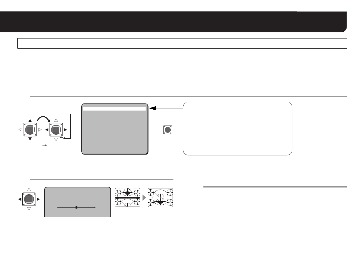
Hiding Image Partially <OPTION> – <PRIVACY MASK>
If privacy protection is required for any shot, apply the masking feature for any position to be prevented from being presented.
The maximum number of masks that can be set is 8.
CAMERA
PRESET POSITION
AUTO MODE
AUTO RETURN
ALARM
PASSWORD
LANGUAGE
·OPTION
·OPTION
Set <MASK 1> to “ON” and press the SET button.
1
·MASK1 ON
PRESET
MENU
·MASK 1
MASK 2
MASK 3
MASK 4
MASK 5
MASK 6
MASK 7
MASK 8
MASK SIZE
PREVIEW
PRESET
MENU
SET y
1 y
SEQ y
OFF
SET y
SET y
SET y
SET y
OFF
END
SET SET
RR R
ON y
OFF
OFF
OFF
OFF
OFF
OFF
OFF
NORM
SET y
OFF
BACK
RThe “DIRECTION” screen appears.
R
·PRIVACY MASK
SET
OPTION
TITLE
·PRIVACY MASK
CONTROL
ADDRESS
ALARM LINE OUT
OFF
SET y
COAX
1
OFF
Perform a single
PRESET
MENU
OFF
BACK
panning to correct the
coordinate origin for
panning and tilting.
Superimpose the objects you want to hide behind
2
the central mask and press the SET button.
DIRECTION
11
RThe “SIZE” screen appears.
SET
R
For accessing the main menu, see pages 7 – 8.
42
Page 44

Hiding Image Partially <OPTION> – <PRIVACY MASK>
Specify the masking size and press the SET
3
button.
SIZE
111
111
RThe “POSITION” screen appears.
Finely adjust the masking position and press the
4
SET
R
SET button.
POSITION
111
111
RReturns to the MASK selection screen.
To set multiple masks, repeat steps 1to4. You may set up to
8 masks.
SET
R
Select <MASK SIZE> and set the masking size
5
adjustment at pan, tilt, or zoom operation.
Sometimes, during pan, tilt, or zoom operation, masked objects
become visible or parts that you want to monitor become masked.
Make the following size corrections as necessary.
MASK 1
MASK 2
MASK 3
MASK 4
MASK 5
MASK 6
MASK 7
MASK 8
·MASK SIZE
PREVIEW
PRESET
MENU
NORM : Normal setting
OVER : Masks larger than NORM.
• Adjusts the masks so that the whole masked area is
hidden even during pan, tilt, or zoom operation.
UNDER : Masks smaller than NORM.
• Limits adjustment to just enough not to hide the
monitoring area during pan, tilt, or zoom operation.
ON y
OFF
OFF
OFF
OFF
OFF
OFF
OFF
NORM
SET y
OFF
BACK
43
Page 45

Hiding Image Partially <OPTION> – <PRIVACY MASK>
■ To preview the entire specified masks
Select <PREVIEW> and press the SET button.
To return to the previous screen, press the SET button again.
(Example: 4 maskings)
MASK 1 2
3333
111
3333
111
22
22
MEMO:
When multiple masking positions
overlap, the masking setting with the
smaller MASK number will be preceded.
4
4
3
4
If masking is set, the camera name will not be displayed on the monitor
Note:
even if <TITLE> is “ON”.
■ To cancel the masking setting
Change “ON” of the MASK number to “OFF” in the MASK selection
screen.
■ To change the previously specified masking setting
Repeat steps from 1 to 4.
Set <MENU> to “END” and press the SET button.
6
RCloses the settings screen and returns to the normal monitoring
screen.
The specified masks appear on the screen.
• If you want to return to the previous screen, select “BACK” and
press the SET button.
If <ALARM SIGN> is “ON” (see page 41), the alarm notification “A”
MEMO:
will be shown on all the masks during the time set in <DURATION>
(see page 40) when an alarm signal comes in.
If both of <ALARM SIGN> and <MOTION> (see page 38) are
“ON”, the alarm notification “A” will be shown when the motion
sensor detects movement.
AA
AAAA
AAA
AAA
AA
AAAA
A
A
• If an alarm or movement is detected while an unmasked image
is being displayed, an alarm notification “A” appears in the top
left corner.
A
44
Page 46

Configuring the Communication Settings <OPTION>
The camera can be operated remotely by connecting a hard disk recorder or controller as a communication device. You need to
configure the conditions for the communication to function.
OPTION
TITLE
PRIVACY MASK
·CONTROL
ADDRESS
ALARM LINE OUT
PRESET
MENU
·OPTION
CAMERA
PRESET POSITION
AUTO MODE
AUTO RETURN
ALARM
PASSWORD
LANGUAGE
·OPTION
PRESET
MENU
SET y
1 y
SEQ y
OFF
SET y
SET y
SET y
SET y
OFF
END
SET
RR
Setting Protocol for Camera Controller <CONTROL>
Select <CONTROL> and specify the protocol for
1
controlling the camera.
OPTION
TITLE
PRIVACY MASK
·CONTROL
ADDRESS
·CONTROL
ALARM LINE OUT
COAX : Coaxial superposition (SANYO: using coaxial cable)
• SSP, Hi-speed SSP and PELCO-C are supported.
Switching among the three is automatic.
485S : RS-485 (SANYO)
• Both SSP and Hi-speed SSP are supported. Switching
between the two is automatic.
485P : RS-485 (PELCO-D)
OFF
SET y
COAX
1
OFF
OFF
SET y
COAX
1
OFF
OFF
BACK
For advanced settings (485S or 485P), press the
2
SET button.
RThe “CONTROL SETTING” screen appears.
• Advance to step 5 if you have selected “COAX”.
Select <BAUD RATE> and specify the
3
communication speed.
CONTROL SETTING
·BAUD RATE
TERMINATE
·BAUD RATE
• Select from: 19200, 9600, 4800, 2400
19200
OFF
For accessing the main menu, see pages 7 – 8.
45
Page 47

Set <TERMINATE> to “ON” or “OFF”.
4
CONTROL SETTING
BAUD RATE
·TERMINATE
19200
OFF
Configuring the Communication Settings <OPTION>
Setting Alarm Output to Communication
Line <ALAR LINE OUT>
Set <ALARM LINE OUT> to “ON” or “OFF”.
1
·TERMINATE
ON : Camera is the cabling termination.
OFF : No termination
Select <MENU> – “BACK” and press the SET
5
button.
RReturns to the “OPTION” screen.
• If you want to finish the settings screen, select “END” and press
the SET button.
Setting Camera Address <ADDRESS>
Select <ADDRESS> and specify an address for
1
the camera (0 - 127).
OPTION
OFF
SET y
COAX
1
OFF
·ADDRESS
TITLE
PRIVACY MASK
CONTROL
·ADDRESS
ALARM LINE OUT
OPTION
OFF
SET y
COAX
1
OFF
OFF
BACK
·
ALARM LINE OUT
TITLE
PRIVACY MASK
CONTROL
ADDRESS
·ALARM LINE OUT
PRESET
MENU
ON : Outputs alarm signals to communication line.
OFF : No output
■ Once the settings are complete
Set <MENU> to “END” and press the SET button.
RCloses the settings screen and returns to the normal monitoring
screen.
• If you want to return to the previous screen, select “BACK” and
press the SET button.
46
Page 48

Troubleshooting
Before seeking repair service, please review the following points first. If the trouble persists, consult your dealer or an
Authorized Sanyo Service Center.
Symptom Items to Be Checked
• Is the coaxial cable connected securely?
• Is lighting appropriate?
No images
available:
Distorted
images:
Unclear
images:
Unrecognizable
subject in the
backlight:
Poor color
images:
Inappropriate
contrast or
outline of
images:
Frequent false
detection by
motion sensor:
• Is power supplied? (see “Connections” in the
INSTALLATION MANUAL.)
• Are power supply and voltage appropriate?
(see “Connections” in the INSTALLATION
MANUAL.)
• Is sync adjusted by the line lock? (see page 15)
• Is the lens transparent without blur? (Use
commercial cleaning paper and liquid to wipe
out.)
• Is the iris adjusted? (see page 17)
• Is backlight compensation specified? (see page
16)
• Is white balance adjusted? (see page 18)
• Did you try Gamma characteristic adjustment?
(see page 22)
• Is the aperture adjusted? (see page 24)
• Is detection sensitivity adjusted? (see page 39)
Symptom Items to Be Checked
(VDC-DP9584S/
VDC-DP9585P)
Distorted
picture after
switching from
COLOR to B/W
mode of
DAY/NIGHT:
• Is “ON” specified for <BURST>? (see pages 26,
27)
Service
The camera is a precision instrument. Handle it carefully and always
follow the safety precautions. If the camera requires service, never try to
repair it yourself or open the casing.
For servicing, maintenance, or repairs, consult your dealer or an
Authorized Sanyo Service Center.
Replacement timing of major parts
If the unit is used continuously, parts will become worn and deteriorated
depending on the environment of use.
It is recommended that parts be replaced approximately every 2 years
(Approximately 1,200,000 times) in order to maintain unit performance.
• Motor, cables used in mechanical parts, gears, etc.
47
Page 49

Specifications
Model name VDC-DP9584S VCC-P9574S VDC-DP9585P VCC-P9575P
Scanning system NTSC standard 525 lines, 60 fields/sec. PAL standard 625 lines, 50 fields/sec.
Image sensor 1/4" interline transfer method CCD
Number of effective pixels 768 (H) x 494 (V) 752(H) x 582(V)
Horizontal resolution More than 520 TV lines
Day/Night mode
Minimum illumination
(approx.)
Video output 1.0 V(p-p)/75 Ω, composite, BNC
Video S/N ratio More than 48 dB (AGC off: More than 50 dB)
Lens Built-in motorized zoom pan focus auto iris lens, f=2.8 - 7.3 mm (2.6x), F=1.9 - 3.0
Depth of field Focus range: 1 m - ∞
Pan/Tilt range
Pan/Tilt speed
Menu On screen display, password lock possible
Preset position 16 positons
Auto mode Sequential pan/Auto pan
Backlight compensation Multi-spot metering (High/Normal)/Center zone metering/OFF
White balance
Gain control High/Normal/Off
Electronic shutter 1/60, 1/100, 1/250, 1/500, 1/1000, 1/2000, 1/4000, 1/10000 sec. 1/50, 1/120, 1/250, 1/500, 1/1000, 1/2000, 1/4000, 1/10000 sec.
Gamma 0.45/1
Aperture compensation High plus/High/Normal/Off
Sync system Internal sync/Line lock
Camera title ON/OFF, Up to 16 characters, adjustable title position
Privacy masking ON/OFF, Max. 8 masked locations
Alarm input External x 2, NO/NC selectable, Alarm preset function, Alarm zoom function
Alarm output External x 1, NO/NC selectable
Motion detector ON/OFF, Motion zoom function
Ceiling Pan: 0 - 335 degrees, Tilt: 0 - 90 degrees
Wall Pan: ±55 degrees, Tilt: 0 - 90 degrees
Preset Max. 120 degrees/sec.
Manual 5 - 100 degrees/sec.
Auto (Low/High)
COLOR, B/W: External control
Gain high:
1.2 lx (F 1.9, COLOR mode)
0.06 lx (F1.9, B/W mode)
Auto-Tracing White Balance (AT W ), One-Push (AWC), Manual White Balance (MWB),
Halogen light or incandescent lamp, etc. (3200), Daytime sunlight (5600), Fluorescent lighting (FLUO)
• The factory setting value is represented in bold.
Gain high: 1.9 lx (F 1.9)
–
Auto (Low/High)
COLOR, B/W: External control
Gain high:
1.2 lx (F 1.9, COLOR mode)
0.06 lx (F1.9, B/W mode)
–
Gain high: 1.9 lx (F 1.9)
48
Page 50

Specifications
Model name VDC-DP9584S VCC-P9574S VDC-DP9585P VCC-P9575P
Communications Simplified controller (VAC-70: Separately ordered) suppor ted
Communication protocol
Waterpro of Standard IP66 – IP66 –
Operating
environment
Power supply
Power consumption
(approx.)
Weight (approx.) 1.5 kg (52.9 oz) 640 g (22.6 oz) 1.5 kg (52.9 oz) 640 g (22.6 oz)
Accessory
Tem pera ture
Humidity Less than 90 % RH (no condensation)
-10°C - +50°C (14°F - 122°F)
-30°C - +50°C (-22°F - 122°F)
• When heater (VA-50H: option
board) is used with power
source connected
24 V AC ±10%, 60 Hz
12 - 15 V DC
• When heater (VA-50H: option
CD-ROM
Installation manual
Warranty (with UL/FCC)
Clamping core
Cushioning sheet
Hexagonal wrench, Large and
Small
Max. 14 W
board) turned on
• The appearance and specifications of the product are subject to change without notice.
Coaxial control: SSP/H-SSP/PELCO-C, RS485:SSP/PELCO-D,
Video out: Coaxial cable/Category 5 LAN cable (NVT built-in UTP video)
-10°C - +50°C (14°F - 122°F)
-10°C - +40°C (14°F - 104°F)
–
CD-ROM
Installation manual
Warranty (with UL/FCC)
Clamping core
-30°C - +50°C (-22°F - 122°F)
• When heater (VA-50H: option
board) is used with power
source connected
24 V AC ±10%, 50 Hz
7 W
• When heater (VA-50H: option
CD-ROM
Installation manual
Clamping core
Cushioning sheet
Hexagonal wrench, Large and
Small
Max. 14 W
board) turned on
12 - 15 V DC
-10°C - +40°C (14°F - 104°F)
–
CD-ROM
Installation manual
Clamping core
49
Page 51

Pattern sheet : mm (inch)
(VDC-DP9584S/VDC-DP9585P)
■ Dimensions
φ
162.0 (6.4)
88.0 (3.5)
82.5 (3.3)
Up (On the wall)
46.0 (1.9)
88.0 (3.5)
Position of the
arrow on the inner
side of the camera
unit base
φ
100.5 (4.0)
114.8 (4.5)
(On the ceiling)
Front
Scale: 1/1
50
Page 52

Pattern sheet : mm (inch)
(VCC-P9574S/VCC-P9575P)
■ Dimensions
φ
150.9 (6.0)
Up (On the wall)
45 .5 (1.8)
51
φ
99.8 (4.0)
115.5 (4.5)
83.4 (3.3)
(On the ceiling)
Scale: 1/1
Front
Page 53

MEMO
52
Page 54

Screen Sequence
Main menu
·CAMERA
PRESET POSITION
AUTO MODE
AUTO RETURN
ALARM
PASSWORD
LANGUAGE
OPTION
PRESET
MENU
OPTION
·TITLE
PRIVACY MASK
CONTROL
ADDRESS
ALARM LINE OUT
Go to page 54 B
LANGUAGE
·LANGUAGE
LANGUE
IDIOMA
SET y
1 y
SEQ y
OFF
SET y
SET y
SET y
SET y
OFF
END
OFF
SET y
COAX
1
OFF
ENGLISH
FRENCH
SPANISH
ON
·SYNC
BLC
IRIS
WHITE BALANCE
AGC GAIN
GAMMA
SHUTTER
APERTURE
DAY/NIGHT
PRESET NO.1
·PRESET POSITION
PRESET ID
SKIP
INT
OFF
SET y
ATW
NORM
0.45
60
HIGH
AUTO y
ON y
OFF
OFF
SEQ PAN
SEQUENTIAL PAN
·ORDER
PAUSE TIME
SPEED
RUN
AUTO RETURN
·MODE
TIME
ALARM SETTING
·ALARM IN
ALARM OUT
MOTION
uAREA
uSENSITIVITY
ZOOM
uZOOM TIME
DURATION
ALARM SIGN
STEP
5S
NORM
SET
SEQ
1M
1 y
NO
OFF
SET y
SET y
OFF
5S
5S
OFF
AUTO PAN
·POSITION
PAUSE TIME
SPEED
RUN
Go to page 54 A
PAN/TILT
STARTy
5S
NORM
SET
ALARM IN SETTING
·POLARITY
MOVE
ALARM OUT
yyy
NO
OFF
OFF
ZOOM
PAN/TILT
SENSITIVITY
<MOVE>
· 5
<TIME>
1
TEST
SET y
PASSWORD
·PASSWORD LOCK
PASSWORD CHANGE
53
OFF y
SET y
PASSWORD
· 1234
x
SET y
PASSWORD
<NOW PASSWORD>
· 1234
x
SET y
PASSWORD
<NEW PASSWORD>
· ????
x
SET y
Page 55

Screen Sequence
AB
·SYNC
BLC
IRIS
WHITE BALANCE
AGC GAIN
GAMMA
SHUTTER
APERTURE
DAY/NIGHT
✱
PRESET
MENU
✱
VDC-DP9584S/VDC-DP9585P
INT
OFF
SET y
ATW
NORM
0.45
60
HIGH
AUTO y
OFF
BACK
L-L
L-L SETTING
<V SYNC PHASE>
· 250
IRIS SETTING
<LEVEL>
· 20
OPTION
·TITLE
PRIVACY MASK
CONTROL
ADDRESS
ALARM LINE OUT
PRESET
MENU
OFF
SET y
COAX
1
OFF
OFF
BACK
ON
485S
485P
TITLE SETTING
y
wABCDEFGHIJKLM
NOPQRSTUVWXYZ
0123456789 :-
ID ????????????????
x
POSITION
SET y
AUTO
DAY/NIGHT SETTING
·LEVEL
BURST
B/W
DAY/NIGHT SETTING
·BURST
LOW
OFF
OFF
AWC
AWC SETTING
·AWC LOCK
GO TO MWB
SET
SET y
MWB
MWB SETTING
· R 43
B 66
CONTROL SETTING
·BAUD RATE
TERMINATE
19200
OFF
·MASK 1
MASK 2
MASK 3
MASK 4
MASK 5
MASK 6
MASK 7
MASK 8
MASK SIZE
PREVIEW
PRESET
MENU
DIRECTION
SIZE
POSITION
ON y
OFF
OFF
OFF
OFF
OFF
OFF
OFF
NORM
SET y
OFF
BACK
54
Page 56

Printed on recycled paper
1AC6P1P3047-L5BL2/US, XE, L5BM2/US, XE (0606KP-SY)
SANYO Electric Co., Ltd.
Printed in Japan
 Loading...