

Page 1
INSTALLATION MANUAL
Color CCD Camera
THIS INSTALLATION SHOULD BE MADE BY A QUALIFIED
SERVICE PERSON AND SHOULD CONFORM TO ALL LOCAL
CODES.
Please read this manual before installing and using this unit, and always follow the instructions
in it for proper use. Please also read the separate INSTRUCTION MANUAL before using the unit
for proper use.
VDC-DP7585P
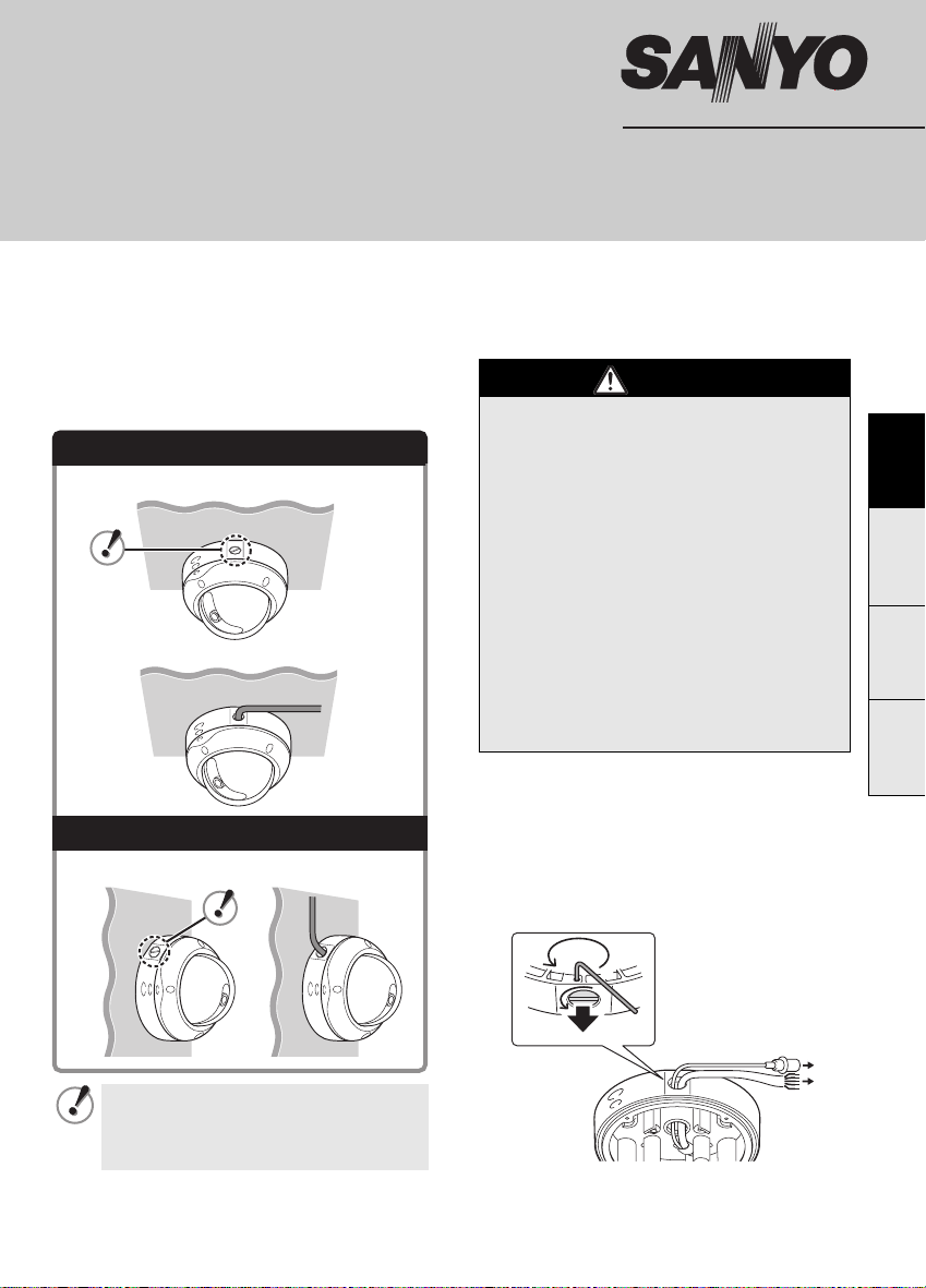
This unit can be installed on the ceiling or wall.
When installing, first remove the built-in camera
from the unit.
Ceiling Installed (see page 1)
(In-ceiling routing)
(Surface routing)
Wall Installed (see page 3)
(In-wall routing) (Surface routing)
Important
• Be careful when opening holes for installing
the unit. Work with the power and video
cables pulled out for easy installation.
• Make sure to properly perform waterproofing
for the ceiling or wall where you are installing
the unit.
• Make sure that the surface in the installation
location has no unevenness and is strong
enough to bear the total weight of the unit.
• Install this unit in an environment where the
temperature range stays between -10°C
and +50°C (no condensation allowed).
• As a precaution against static electricity
damage, touch a nearby metal object (door
knob, etc.) to dissipate static electricity in
your body before touching this unit.
b When routing the cables on ceiling or wall
surfaces:
Loosen the conduit hole cover fixing screw (A)
on the back of the camera unit base with the
hexagonal wrench (small), open the cover (B),
and pass the connection cables through the
conduit hole.
A
EnglishFrançaisDeutsch中文简体
Since the conduit hole cover is not
waterproof-finished, always be sure to
seal the cover entirely by puttying, for
example, upon completion of installation.
B
Page 2
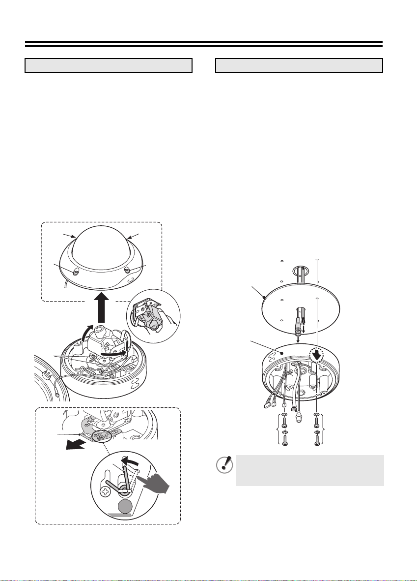
Installing on the Ceiling
1. Remove the camera unit
Loosen the four screws (A) using the
1
hexagonal wrench (large) and open the
dome cover.
Unplug all the pin connector cables from
2
the circuit board.
Lift and turn the camera unit in the
3
arrowed directions so that the two
screws (B) become visible.
Pull out the sliding plate (D) in the
4
arrowed direction while pushing the
spring (C) indicated with a blue sticker
in the arrowed direction.
The camera unit is released.
1
A
A
A
A
3
B
2. Install the camera unit base
Attach the cushioning sheet (E) to the
1
back of the camera unit base (F), open a
cable hole in the cushioning sheet, and
pass the cables through the cable hole.
Position the arrow (2) on the inner side
2
of the camera unit base (F) in the
direction of the lens.
The arrow is located roughly in the center of
the panning range.
Set the camera unit base (F) on the
3
ceiling and secure it by tightening
suitable screws and washers (G)
through the screw holes (4 places).
• Length: 35 mm or more
• Diameter: 3.5 to 5.0 mm
• Height of screw head: 5 mm or less
(washer included)
E
1
F
2
4
2
3
D
C
Make sure to tighten the screws properly.
Using screws of sizes other than
specified may cause the unit to fall.
G
1
G
Page 3
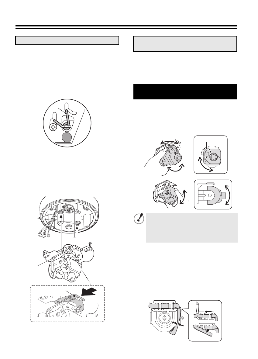
3. Mount the camera unit
Connect the cables from the ceiling.
1
Push the excess of connected cables into
the ceiling.
For details on the connections, see page 5.
Check that the spring (H) on the base
2
chassis looks as shown in the figure
below.
4. Adjust/Check the video image
from the camera
b Set up the camera remotely (see page 7).
b Check the settings screen or camera
angle on a portable monitor (see page 7).
Adjusting the lens position
and shaping the flat cable
H
Mount the camera unit using the two
3
base screws (J).
Push the sliding plate (K) in the arrowed
4
direction until it clicks, then connect the
pin connector cables from the camera
unit base to the circuit board.
J
2
H
4
K
Adjust the angle of view by moving the
1
lens unit manually.
Make the arrow (AA) beside the lens point
upwards (the video image will be upside
down if pointing downwards).
330°
180°
90°
Vertical or horizontal smear (streak
noise) may appear if the camera faces
an extremely bright light source. If so,
change the lighting angle while checking
the quality of the image on the monitor.
Shape the flat cable on the back of the
2
lens unit.
1 Hook the cable on the back of the clamp
as shown in the figure.
2 Pull the cable in the arrowed direction
until the sag is gone.
3
Fold over the excess cable until there is no
more sag and insert it into the holder slits.
AA
2
1
3
2
Page 4

Installing on the Ceiling
Installing on the Wall
5. Install the dome cover
Align the logo on the dome cover with
1
the mark (L) on either side of the camera
unit base so that the lens is close to the
camera window (M).
Loosen the screws (N) in the inner side
2
of the dome cover and shift the dome
liner (P) until the lens is completely
visible from the camera window.
Secure the dome cover by tightening the
3
screws (R) (4 places) firmly using the
hexagonal wrench (large).
L
R
1. Remove the camera unit
See “Installing on the Ceiling” (see page 1).
2. Install the camera unit base
Attach the cushioning sheet (A) to the
1
back of the camera unit base (B), open a
cable hole in the cushioning sheet, and
pass the cables through the cable hole.
Set the camera unit base (B) on the wall
2
so that its tightening screws (C) are
perfectly horizontal, then tighten them
securely with washers (4 places).
• Length: 35 mm or more
• Diameter: 3.5 to 5.0 mm
• Height of screw head: 5 mm or less
(washer included)
B
R
M
A
C
N
P
C
3
Page 5

3. Mount the camera unit
Connect the cables from the wall.
1
Push the excess of connected cables into the wall.
For details on the connections, see page 5.
Check that the spring (D) on the base
2
chassis looks as shown in the figure
below.
D
Mount the camera unit using the two
3
base screws (E).
Push the sliding plate (F) in the arrowed
4
direction until it clicks, then connect the
pin connector cables from the camera
unit base to the circuit board.
E
4. Adjust/Check the video image
from the camera
b Set up the camera remotely (see page 7).
b Check the settings screen or camera
angle on a portable monitor (see page 7).
If the image is upside down, correct the
orientation by turning down the lens unit,
rotating it 180 degrees, and then turning it up
in the arrowed directions.
• The video image will be upside down
if the arrow (AA) beside the lens
points downwards.
AA
• Be careful not to damage the flat
cable when rotating the lens unit.
4
E
F
See “Adjusting the lens position and
shaping the flat cable” on page 2.
5. Install the dome cover
See “Installing on the Ceiling” (see page 3).
4
Page 6

Connections
Do not connect the power cord until all other connections have been completed.
DC12 AC24
+–~
GND
DAY/NIGHT
ALARM IN
TELE
WIDE
COMMON
BNC type
RED
BLACK
WHITE
YELLOW
PURPLE
ORANGE
BLUE
GRAY
~
RG-6U, 300 m max.
Monitor Connection
For the connection, use a RG-6U coaxial
cable.
• Using different cables from those
specified here may attenuate the
video and/or sync signals and
interfere with correct transmission.
• RG-59U coaxial cables can be
used when distance between
devices is short, but not in duct or
aerial routing.
Cable type Length
RG-59U (3C-2V) 150 m max.
RG-6U (5C-2V) 300 m max.
RG-11U (7C-2V) 350 m max.
To prevent electromagnetic
interference
• On the cable for power supply
Be sure to attach the supplied clamping
core to the cables as illustrated.
Power Supply Connection
b With AC 24 V
(RED)
(BLACK)
(WHITE)
For the connections, use cables thicker than
18 AWG.
b With DC 12 V
Check that +/- polarity is correct.
(RED)
(BLACK)
For the connections, use cables thicker than
18 AWG.
~
~
GND
+
–
5
Page 7

All connection cables should be 24 AWG or higher with a maximum length of no
more than 600 m.
Color or Black-and-White Setting
The video image can be fixed to be color or
Alarm Signal Input
For details, see “Specifying Alarm Input” in
the INSTRUCTION MANUAL.
black-and-white using an external switch.
For details, see “Adjusting DAY/NIGHT
Function” in the INSTRUCTION MANUAL.
(PURPLE)
(GRAY)
SYNC
BLC
IRIS
WHITE BALANCE
AGC GAIN
GAMMA
SHUTTER
APERTURE
DAY/NIGHT
·OPTION
PRESET
MENU
OPTION
TITLE
PRIVACY MASK
PASSWORD
·ALARM
LANGUAGE
INT
OFF
SET y
ATW
NORM
0.45
50
HIGH
AUTO y
SET y
OFF
END
OFF
SET y
SET y
SET y
SET y
Alarm
input signal
Connection for Zoom Input
It is used to make wide angle/telescoping
adjustments.
(ORANGE)
(GRAY)
(BLUE)
Zoom Input Signal
TELE WIDE
Open: Color
Closed: Black-and-White
(YELLOW)
(GRAY)
• Make sure that COLOR is selected.
SYNC
BLC
IRIS
WHITE BALANCE
AGC GAIN
GAMMA
SHUTTER
APERTURE
·DAY/NIGHT
OPTION
PRESET
MENU
INT
OFF
SET y
ATW
NORM
0.45
50
HIGH
COLORy
SET y
OFF
END
For customers using the option board
(heater: VA-50H)
For this unit, the main board (A) is
sufficient to raise the temperature. Always
be sure to remove the sub board (B).
A
B
6
Page 8

Adjusting the Camera
bSetting up the camera remotely
Use of the separately ordered Camera Control Unit (VAC-70) is recommended for setting and adjustment of
this camera. Advanced settings are possible from the main menu. For details, see the instruction manual for
the Camera Control Unit
Do not forget to disconnect the Camera Control Unit once you have finished setting/adjustment.
Checking the settings screen or camera angle on a portable monitor
(These checks are unnecessary when using the separately
ordered Camera Control Unit (VAC-70).)
Connect the MONITOR OUT pin and the GND pin on the circuit
board to a monitor using an alligator clip cable. Do not forget to
remove the cable after you have finished checking.
A dedicated MONITOR OUT connector is provided for portable
monitors.
b To check the settings screen and make changes
1) Hold down the SET button (1) for over a second.
The main menu appears.
2) Select a menu by pressing the Select button (2) up and
down.
3) Select the setting item and value by pressing the Select
button left and right.
.
Video in
VAC -7 0
VIDEO OUT CAMERA
DC IN 3V
Ð+
BNC type
RG-6U coaxial cable
300 m max.
GND
MONITOR
OUT
SET
UP
LEFT
RIGHT
DOWN
1
2
b To check the zoom position and make changes
Press the Select button left and right during live mode
(with no menu displayed).
You can set the zoom (wide: d, tele: c).
bInstallation accessories
1 Hexagonal wrench
(large, small)
2 Cushioning sheet 3 Clamping core
7
 Loading...