

Page 1
INSTRUCTION MANUAL
Colour Compact Pre-set Camera
VCC-9250P
About this manual
Before installing and using this unit, please read this manual
•
carefully. Be sure to keep it handy for later reference.
This manual gives basic connections and operating
•
instructions.
Page 2

CONTENTS
PRECAUTIONS
FEATURES ...................................................... 1
PRECAUTIONS ............................................... 1
PARTS NAMES ............................................... 2
CONNECTIONS............................................... 4
FUNCTIONS .................................................... 6
BASIC OPERATION........................................ 8
INSTALLATION...............................................10
ADDRESS SETTING TABLE ..........................11
SPECIFICATIONS ...........................................13
FEATURES
This compact preset camera can be controlled remotely for
horizontal and vertical movement. It is used with a system
controller (VSP-7000), sold separately. The camera 24V AC
power supply is connected through the power unit, and the
camera operation is controlled remotely from the system
controller through a serial connection to the RS-485 connector
using a twisted-pair cable.
1/3 inch solid state image device CCD (approx. 470,000
picture elements)
Up to 96x zoom possibility (12x optical zoom, 8x
electronic zoom)
Horizontal resolution of more than 450 TV lines, video
S/N ratio more than 48 dB for high resolution. High
sensitivity, with a minimum required illumination of 3.5
lux
Horizontal, vertical turn function
Preset movement speed:
horizontal 240˚/s, vertical 120˚/s
Manual movement minimum speed:
horizontal 0.6˚/s, vertical 0.3˚/s
Speed ratio: 400:1
Continuous horizontal turn range (360˚)
ACCESSORY
Clamping core ....................................................................2 pc.
•
In case of problem
Do not use the camera if smoke or a strange odour comes from
the unit, or if it seems not to function correctly. Disconnect the
power cord immediately, and consult your dealer (or a Sanyo
Authorized Service Centre).
Do not open or modify
Do not open the cabinet, as it may be dangerous and cause
damage to the unit. For internal settings and repairs, consult
your dealer (or a Sanyo Authorized Service Centre).
Do not put objects inside the unit
Make sure that no metal objects or flammable substance get
inside the camera. If used with a foreign object inside, it could
cause a fire, short-circuits or damages.
If water or a liquid gets inside the camera, disconnect the power
cord immediately, and consult your dealer (or a Sanyo
Authorized Service Centre). Be careful to protect the camera
from rain, sea water, etc.
Be careful when handling the unit
To prevent damages, do not drop the camera or subject it to
strong shock or vibration.
Install away from electric or magnetic fields
If installed close to a TV, radio transmitter, magnet, electric
motor, transformer, audio speakers the magnetic field they
generate will distort the image.
Protect from humidity and dust
To prevent damages to the camera, do not install it where there
is greasy smoke or steam, where the dampness may get too
high, or where there is a lot of dust.
Protect from high temperatures
Do not install close to stoves, or other heat generating devices,
such as spotlights, etc., or where it could be subject to direct
sunlight, as that could cause deformation, discoloration or other
damages.
Be careful when installing close to the ceiling, in a kitchen or
boiler room, as the temperature may raise to high levels.
Install where the temperature range will stay between 0˚C and
45˚C. (no condensation)
Cleaning
Dirt can be removed from the cabinet by wiping it with a soft
•
cloth. To remove stains, wipe with a soft cloth moistened with
a soft detergent solution and wrung dry, then wipe dry with
dry soft cloth.
Do not use benzine, thinner or other chemical product on the
•
cabinet, as that may cause deformation and paint peeling.
Before using a chemical cloth, make sure to read all
accompanying instructions. Make sure that no plastic or
rubber material comes in contact with the cabinet for a long
period of time, as that may cause damage or paint peeling.
This camera should be used together with the power unit
which is supplied with the camera.
Other commercially-available power units should never
be used, as they may damage the camera or result in
electric shocks.
1
Page 3
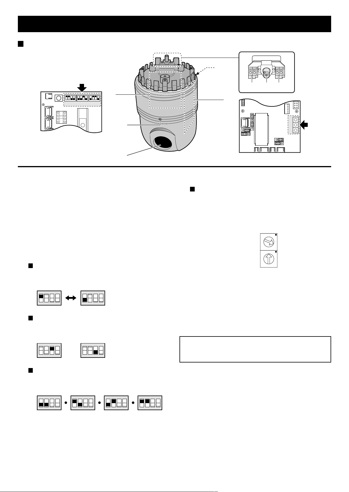
PARTS NAMES
CN5
SW1 SW2 SW3
Camera
4
6
5
RS485 AC24V
A
R
N
B
321
6
(External sync control circuit board)
7
1 24V AC power input terminals (AC24V)
Connect the camera power input terminals to the power unit
output terminals (AC24V OUT).
2 Video output terminal (BNC connector)
To connect this camera to a device such as a monitor or
timelapse VCR.
3 RS-485 serial signal input terminals (RS485)
Make the connection between the RS-485 terminals of the
camera, power unit, system controller, using twisted-pair
cables or modular cables (sold separately).
4 External sync control circuit board
Termination setting (SW1)
Set the termination ON/OFF using DIP switch No. 1 of
switch SW1. The default setting in : “ON”
(Terminater ON)
123
F
F
O
SW1
Sync setting (SW2)
Set the internal sync or line-lock using DIP switch No. 3
of switch SW2. The default setting in : “ON (INT)”
(Internal sync)
123
F
F
O
SW2
4
4
(Terminater OFF)
123
4
F
F
O
(Line-lock)
123
4
F
F
O
SW2
SW1SW2SW3
(Control circuit board)
5 Control circuit board
Address setting
When using the camera with a power unit, the address
for both must be the same.
Assign the hexadecimal (base 16) address using
switches SW1 and SW2. Address settings are from 1 to
127. Refer to “ADDRESS SETTING TABLE” on page
11, for details. The default setting in : “1”
0
1
F
2
E
3
D
4
C
5
B
6
A
7
9
8
SW1SW2
0
1
F
2
E
3
D
4
C
5
B
6
A
7
9
8
6 Cover attaching screw
Loosen the two screw the remove the cover to access the
external sync control circuit board and address setting
panel. Make sure to turn off the power to the camera before
removing the cover.
7 Lens
Always be sure to turn off the power supply before
changing any of the switch settings on the external sync
control circuit board or the control circuit board.
Data transmission speed setting (SW3)
Set the data transmission speed using DIP switch No. 1
and 2 of switch SW3. The default setting in : “19200”
(2400 bps)
123
F
F
O
SW3
4
(4800 bps)
123
F
F
O
4
(9600 bps)
123
F
F
O
4
(19200 bps)
123
F
F
O
4
2
Page 4
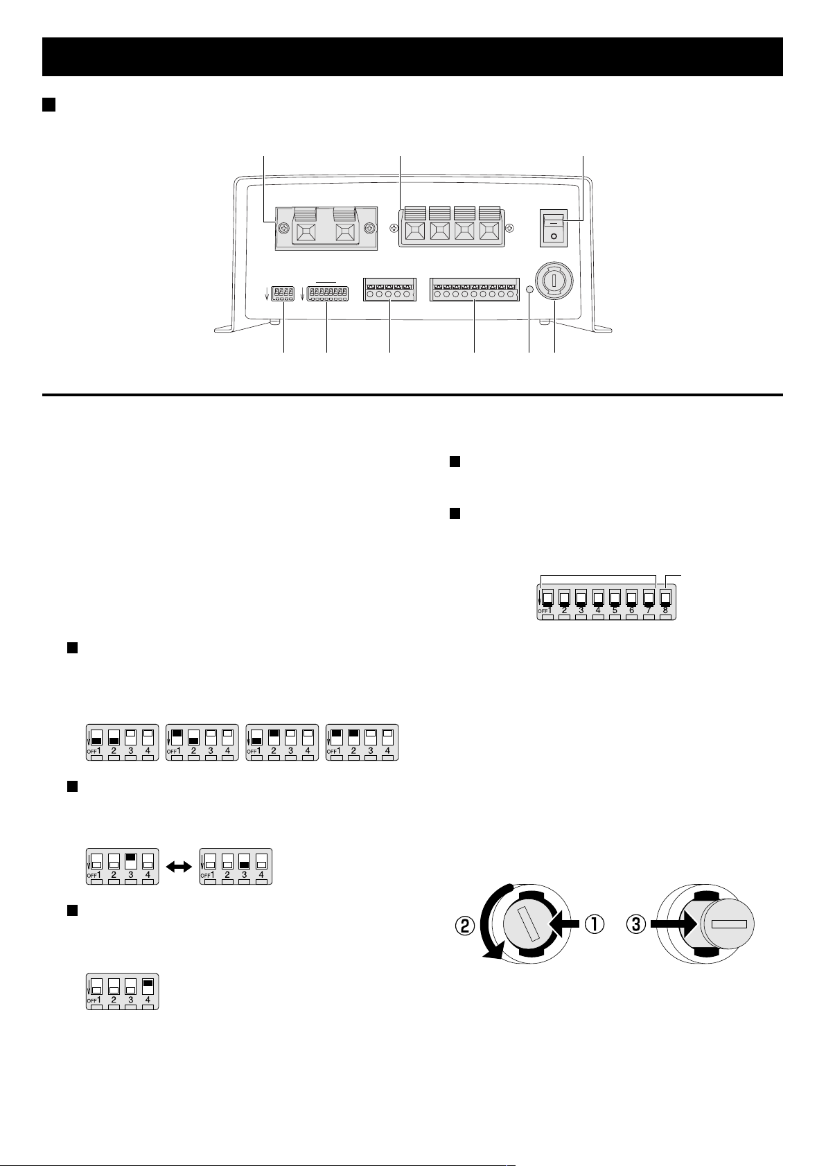
PARTS NAMES
Power unit
1 2 3
AC24V OUT
8
TERMINATE
RS-485 DATA
A B A B G
RS-485
BAUD RATE
1 4 1 7
OFF OFF
4
RS-485
ADDRESS
5 6 7 8 9
1 24V AC output terminals (AC24V OUT)
Connect the camera power input terminals (AC24V) to the
power unit output terminals.
2 24V AC input terminals (AC24V IN)
Connect the AC 24V power input to the power unit. When
making the connections, make sure to turn off the power at
the source.
3 Power switch (POWER)
To turn the power on or off. Will also control the power to
the camera.
4 Transmission speed setting switch (RS-485 BAUD RATE)
The default setting is all “ON”.
Transmission speed setting (SW1, 2)
The default setting is 19200 bps. If necessary, change
the setting according to the maximum transmission
speed supported by the peripheral devices.
(2400 bps) (4800 bps) (9600 bps) (19200 bps)
Alarm duration setting (SW3)
The default setting is 5 sec. If necessary, change the
setting according to the type of alarm signal input.
(5 sec.) (30 sec.)
AC24V IN
ALARM IN
1 2 3 4 5 6 7 8 G
POWER
5 Address/Terminate setting switch (RS-485 ADDRESS/
TERMINATE)
Address setting (SW1 to SW7)
Set the power unit address. See the table on page 12, for
details.
Termination setting (SW8)
The power unit termination must be set. The default
setting is all OFF (up).
ADDRESS SET
TERMINATER
ON/OFF
6 RS-485 control terminal (RS-485 DATA)
Make the connections between the RS-485 terminals of the
camera, power unit, system controller, etc. using
twisted-pair cable or modular cable (sold separately). Signal
A must be connected to A, and signal B to B.
7 Alarm input terminals (ALARM IN)
Connect alarm input sources such as a door bell, an
interphone, etc. to the ALARM IN terminals. Refer to
“Connections to the ALARM IN terminal” on page 4, for
more information on connections.
8 Power indicator viewing hole
The indicator inside the hole illuminates when the power is
turned on.
9 Fuse socket
Alarm list display setting (SW4)
The alarm list can be displayed on the menu screen of
the system controller.
The default setting is “ON”.
3
Page 5
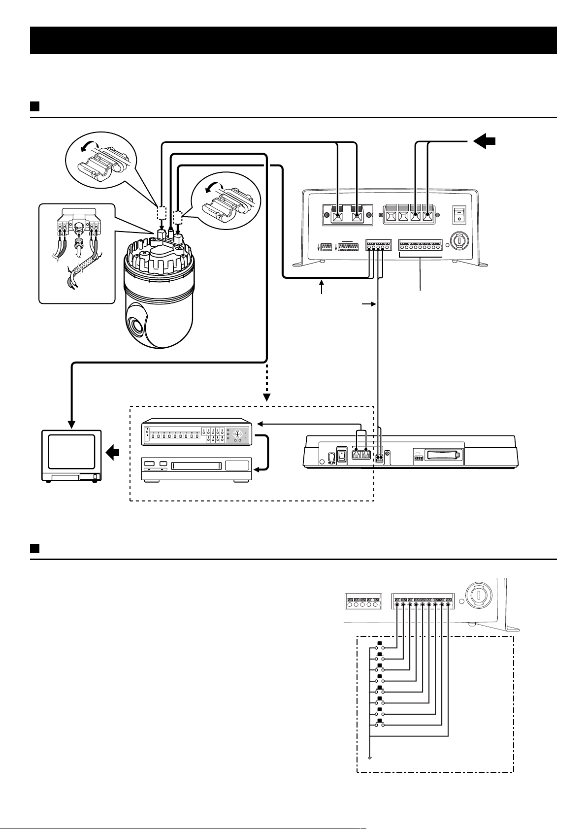
CONNECTIONS
Before making any connection, make sure all the devices are turned off.
Before making the connections, please refer to the instruction manual accompanying each device.
Basic connections
R
N
To signal A
RS485 AC24V
A
B
To signal B
Coaxial cable (sold separately)
Power supply cord (sold separately)
Twisted-pair cable
(sold separately)
Modular cable (sold separately)
AC24V OUT
RS-485
BAUD RATE
1 4 1 7
OFF OFF
RS-485
ADDRESS
TERMINATE
8
RS-485 DATA
A B A B G
AC24V IN
ALARM IN
1 2 3 4 5 6 7 8 G
Alarm input terminals
AC 24 INPUT
POWER
Multiplexer (sold separately)
12V DC IN
POWER
ON
OFF
AAB
GND
B
ADDRESS
123
TERMINATE
1
0
RS485
System controller
Monitor
(sold separately)
Timelapse VCR (sold separately)
(sold separately)
Note: When using this unit, the supplied clamping core must be installed on the power cord and twisted-pair cable, in order to prevent
electromagnetic interference to the other devices connected.
Connections to the ALARM IN terminal
Connect alarm input sources such as a door bell, an interphone,
etc. to the ALARM IN terminals. When an alarm trigger is
received at the alarm input terminals, the camera will move to its
corresponding preset position.
RS-485 DATA
A B A B G
ALARM IN
1 2 3 4 5 6 7 8 G
External alarm sensors
(door bell, interphone, etc.)
Common
4
Page 6

CONNECTIONS
Multiple cameras connections
When the cameras are connected to the power units without an RS485 control terminal connection, up to 127 sets can be used.
•
However, if the connection is made between the power unit RS485 control terminal and the camera, a power unit can only control
one camera and up to 64 sets only can be used.
To connect multiple units, connect the RS-485 cables to the power units and the RS-485 cables to the cameras in a daisy chain
•
fashion.
The termination should be set to ON for the last camera connected to the daisy chain.
•
AC24V OUT
RS-485
RS-485
BAUD RATE
ADDRESS
1 7
1 4
OFF OFF
8
TERMINATE
Camera 64
(termination ON)
(sold separately)
AC 24 INPUT
AC24V IN
ALARM IN
RS-485 DATA
A B A B G
1 2 3 4 5 6 7 8 G
(sold separately)
POWER
RS-485
BAUD RATE
OFF
Camera 2
(termination OFF)
(sold separately)
1 4
AC24V OUT
RS-485
ADDRESS
1 7
OFF
8
TERMINATE
RS-485 DATA
A B A B G
B
AC24V IN
RS485
A
AC 24 INPUT
POWER
ALARM IN
1 2 3 4 5 6 7 8 G
(sold separately)
RS-485
BAUD RATE
1 4
OFF
Camera 1
(termination OFF)
AC24V OUT
RS-485
ADDRESS
1 7
OFF
8
TERMINATE
RS-485 DATA
A B A B G
AC24V IN
AC 24 INPUT
ALARM IN
1 2 3 4 5 6 7 8 G
Power unit
POWER
Monitor Monitor
(sold separately)
Monitor
(sold separately)
System controller (sold separately)
RS485
AB
5
Page 7

FUNCTIONS
Preset memory function
The preset memory function will memorise camera positions and
zoom, focus, etc. settings. Up to 255 preset camera positions
can be memorised. Later, you can easily recall any of the preset
camera positions by entering its corresponding number, and the
camera will move to the memorised position with all the preset
settings.
Home position
The camera position preset as number 1 is called the “Home
position”.
Use the home position as the normal camera position.
•
No.1
Preset position No. 1 (Home position)
Moving to a preset position
When camera positions have been preset, you can enter a
memorised camera position number (ex.: 25), using the numeric
keypad buttons on the system controller to select it. The camera
will set itself to the select preset position.
Auto pan function
The auto pan function allows you to have the camera move back
and forth automatically, at a preset speed, between the 2 preset
camera positions memorised in numbers 7 (start position) and 8
(end position).
Before this function can be used, the auto pan start position
•
(No. 7) and the auto pan end position (No. 8) must be preset.
When the auto pan function is started
1 The camera will move from its actual position to the auto pan
start position (No. 7).
No.7
Preset position No. 7
2 The camera will move from the auto pan start position (No. 7)
to the auto pan end position (No. 8).
Note: The camera will turn counterclockwise when moving
from the start position to the end position.
No.25
Preset position No. 25
Pan/tilt function
The pan function will move the camera on an horizontal plane, to
a surveillance position.
The tilt function will move the camera on a vertical plane, to a
surveillance position.
No.8
No.7
Preset position No. 7
Preset position No. 8
3 The camera will move back from the auto pan end position
(No. 8) to the auto pan start position (No. 7).
No.8
No.7
Preset position No. 8
4 Steps 2 and 3 are repeated.
6
Preset position No. 7
Page 8

FUNCTIONS
Sequential pan function
You can set the camera to move sequentially to the 6 preset
camera positions memorised in numbers 1 to 6.
Before this function can be used, the 6 sequential pan
•
positions (No. 1 to 6) must be preset.
When the sequential pan function is started
1 The camera will move from its actual position to the home
position (No. 1).
No.1
Preset position No. 1
2 The camera will move from the home position (No. 1) to
preset position No. 2.
No.1
No.2
Preset position No. 1
4 The camera will move back from position No. 6 to the home
position (No. 1).
No.1
Preset position No. 1
5 Steps 2 to 4 are repeated.
Iris function
The camera iris level can be adjusted.
15 different iris levels can be set.
One-push (AWC SET) white balance
function
White balance adjustment can be carried out to compensate for
the type of lighting (daylight, incandescent lighting, etc.).
Depending on the lighting conditions, true colours may not
always be obtained.
Zoom function
The filming range can be set using the zoom function.
Wide angle zoom
Preset position No. 2
3 The camera will then move sequentially to positions No. 3,
No. 4, No. 5 and No. 6.
Preset position No. 3Preset position No. 2
Preset position No. 4
Preset position No. 5Preset position No. 6
Telephoto zoom
Backlight compensation function (BLC)
The backlight compensation is used when the background is
bright and the subject comes out too dark.
Without backlight
compensation
With backlight
compensation
Electronic shutter function
The shutter speed can be set according to the filming conditions.
4 different speed settings can be set.
Focus function
The focus can be set automatically or manually.
7
Page 9

BASIC OPERATION
Connect the camera to the power unit and to the system controller (sold separately), then use the system controller to operate the
camera. This section principally gives instructions concerning the camera and the power unit.
1 Make all the connections.
Turn off the power to all the devices.
2 Remove the camera cover.
Remove the cover attaching screw, then remove the cover.
3 Termination setting
Camera: The termination is set using DIP switch No. 1 of
switch SW1 on the external sync control panel. Set
the termination to ON for the last unit only,
termination on all other units must be set to OFF.
Power unit: The termination is set using DIP switch No. 8 of
the RS-485 ADDRESS switch on the power unit.
System controller: The termination is set using the
TERMINATE DIP switch on the system
controller rear panel.
4 Data transmission speed setting
Camera: Set the data transmission speed using DIP
switches No. 1 and 2 of switch SW3 on the external
sync control circuit board. The default setting is
19200 bps.
Power unit: Set the data transmission speed using DIP
switches No. 1 and 2 of the RS-485 BAUD
RATE switch on the power unit.
System controller: Set the data transmission speed in
BAUD RATE SET on the menu screen.
Note: Make sure all connected devices transmission speed
settings are the same.
5 Address setting
Camera: Set the address using switches SW1 and SW2 of
the control circuit board. The address default
setting is “01”.
Power unit: Set the address using switches DIP switches
No. 1 to 7 of the RS-485 ADDRESS switch.
System controller: Set the address using the ADDRESS
DIP switches on the system controller
rear panel.
Note:
Address settings are from 1 to 127. See the tables on
•
pages 11 and 12, for details on setting the addresses for
the camera and the power unit.
Make sure the address of the power unit is the same as
•
the one for the corresponding camera.
6 Tighten the cover attaching screw to install the cover,
then turn all the devices on.
7 Operation using the system controller
The following two operating modes are available. For detailed
instructions, please refer to the system controller instruction
manual.
Direct operation using the Camera command
(CAMERA) buttons on the system controller
This method allows you to set the backlight correction, the
electronic shutter function, etc., to adjust the image
according to the conditions when filming by adjusting the
camera basic settings.
Camera command
(CAMERA) buttons
Operation using the FUNCTION button to call-up
commands, and selecting a command from the six
types of commands available
This method allows you to use the special functions of the
camera, such as the auto vertical and horizontal
movement function, and to memorise camera angles that
can then be used with the auto-pan or the sequential pan
functions.
(Call-up commands)
ALARM OUT
•
AUTO PAN
•
SEQUENCE
•
PRESET MEMORY
•
L-L PAHSE
•
RESET
•
Numeric keypad buttons
FUNCTION button
8
Page 10

BASIC OPERATION
Alarm operation
If alarm input sources such as a door bell, an interphone, etc.,
are connected to the ALARM IN terminals on the power unit,
when an external alarm trigger is received at the alarm input
terminals, the camera will move to its corresponding preset
position.
Also, the alarm list can be displayed on the menu screen of the
system controller. Refer to page 4, for more information on
connections.
1 Alarm operation setting
Select “ALARM OUT” on the system controller call-up
commands, then set it to “ON”.
2 Alarm duration setting
Set the duration using DIP switch No. 3 of the RS-485 BAUD
RATE switch.
For example, if the duration is set to ON (5 seconds), after an
alarm is triggered another alarm will not be received for 5
seconds.
The default settings are ON (5 sec.).
(Displaying the alarm list)
This is done using DIP switch No. 4 of the RS-485 BAUD
RATE switch.
The default setting is ON (alarm list displayed), if set to OFF
the alarm list will not be displayed.
Power supply synchronization setting
(L-L)
Make this adjustment if the image on monitor rolls vertically.
1 Select the sync signal
Select the internal sync (INT) or the line-lock using DIP switch
No. 2 of switch SW1 and DIP switch No. 3 of switch SW2 on
the external sync control panel.
When the internal sync is set to OFF, DIP No. 3 of SW2
•
must also be set to ON.
When the line-lock is set to ON, DIP No. 3 of SW2 must
•
also be set to OFF.
2 Vertical sync adjustment
Select “L-L PHASE” on the system controller call-up
commands, then adjust the vertical sync phase.
9
Page 11

INSTALLATION
This camera unit is designed to be hanged from a ceiling. Other installation method may cause abnormal operation.
Refer to the mounting bracket (sold separately) etc. instruction manual.
Location
Ceiling structure
•
The ceiling must be strong enough to support the weight of
the camera and its accessories. Do not mount to a surface
that may vibrate when the camera is operating.
Protect from water leaks
•
This unit is to be used indoors exclusively. Do not install it
where it may be exposed to water leaking from pipes, rain,
etc.
Protect from vibrations
•
Never mount to a ceiling surface that may be subjected to
vibration or shocks.
Protect from damages due to humidity
•
The camera must be installed at a minimum distance of 1.5 m
from the air outlet of an air conditioning. If it cannot be helped,
and the camera is installed close to an air conditioning, make
sure the air flow is not directed towards the camera. If
necessary, install a cover or other protection to deflect the air.
If cold air is directed onto the camera, that may fog the lens
and the image may be blurred. Also, condensation may form
on metal parts inside the unit and that may cause corrosion
and other damages.
Maintaining safety
•
This camera unit is designed to be used hanging from a
ceiling. It is therefore very important to ensure safety by
carefully reading the mounting bracket instruction manual and
making sure it is secure and that there is no risk of the
bracket falling down.
Filming results
Ghosting
•
If a light source (such as a spotlight, etc.) is directed to the
camera lens, even if it is not in the filming range, there may
be ghosting (apparition of a secondary image).
This can be corrected by changing the light source direction
or position, or the camera location.
Reproduction of colours
•
If the lighting in the area covered by the camera is of a single
type (all fluorescent or all incandescent), the colours can be
reproduced accurately. However, if the lighting type is mixed
(fluorescent and incandescent), the colours may not be
reproduced properly.
Subject illumination
•
This camera can accommodate a wide range of lighting
intensities. However, the minimum lighting intensity for the
main subject is 20 lux with the zoom in wide angle position
and 40 lux in telephoto position. This level should be
maintained with additional lighting, in particular at night or in a
dark environment.
10
Page 12

ADDRESS SETTING TABLE
S
S
Camera
Address
(camera
number)
Switch number
0
1
F
2
E
3
D
4
C
5
B
6
A
7
9
8
SW2
W1
0
1
F
2
E
D
C
B
A
7
9
8
0 (no use) 0 0
101
202
303
404
505
606
707
808
909
10 0 A
11 0 B
12 0 C
13 0 D
14 0 E
15 0 F
16 1 0
17 1 1
18 1 2
19 1 3
20 1 4
21 1 5
22 1 6
23 1 7
24 1 8
25 1 9
26 1 A
27 1 B
28 1 C
29 1 D
30 1 E
31 1 F
32 2 0
33 2 1
34 2 2
35 2 3
36 2 4
37 2 5
38 2 6
39 2 7
40 2 8
41 2 9
42 2 A
3
4
5
6
(camera
number)
43 2 B
44 2 C
45 2 D
46 2 E
47 2 F
48 3 0
49 3 1
50 3 2
51 3 3
52 3 4
53 3 5
54 3 6
55 3 7
56 3 8
57 3 9
58 3 A
59 3 B
60 3 C
61 3 D
62 3 E
63 3 F
64 4 0
65 4 1
66 4 2
67 4 3
68 4 4
69 4 5
70 4 6
71 4 7
72 4 8
73 4 9
74 4 A
75 4 B
76 4 C
77 4 D
78 4 E
79 4 F
80 5 0
81 5 1
82 5 2
83 5 3
84 5 4
Address
Switch number
0
1
F
2
E
3
D
4
C
5
B
6
A
7
9
8
SW2
F
E
D
C
B
A
SW1
0
1
2
3
4
5
6
7
9
8
Address
(camera
number)
86 5 6
87 5 7
88 5 8
89 5 9
90 5 A
91 5 B
92 5 C
93 5 D
94 5 E
95 5 F
96 6 0
97 6 1
98 6 2
99 6 3
100 6 4
101 6 5
102 6 6
103 6 7
104 6 8
105 6 9
106 6 A
107 6 B
108 6 C
109 6 D
110 6 E
111 6 F
112 7 0
113 7 1
114 7 2
115 7 3
116 7 4
117 7 5
118 7 6
119 7 7
120 7 8
121 7 9
122 7 A
123 7 B
124 7 C
125 7 D
126 7 E
127 7 F
Switch number
0
1
F
2
E
3
D
4
C
5
B
6
A
7
9
8
SW2
W1
0
1
F
2
E
3
D
4
C
5
B
6
A
7
9
8
85 5 5
11
Page 13

ADDRESS SETTING TABLE
Power unit
Address
(camera
number)
0
1ON
2ON
3ONON
4ON
5ONON
6ONON
7ONONON
8ON
9ON ON
10 ON ON
11 ON ON ON
12 ON ON
13 ON ON ON
14 ON ON ON
15 ON ON ON ON
16 ON
17 ON ON
18 ON ON
19 ON ON ON
20 ON ON
21 ON ON ON
22 ON ON ON
23 ON ON ON ON
24 ON ON
25 ON ON ON
26 ON ON ON
27 ON ON ON ON
28 ON ON ON
29 ON ON ON ON
30 ON ON ON ON
31 ON ON ON ON ON
32 ON
33 ON ON
34 ON ON
35 ON ON ON
36 ON ON
37 ON ON ON
38 ON ON ON
39 ON ON ON ON
40 ON ON
41 ON ON ON
42 ON ON ON
Switch number
Address
(camera
number)
43 ON ON ON ON
44 ON ON ON
45 ON ON ON ON
46 ON ON ON ON
47 ON ON ON ON ON
48 ON ON
49 ON ON ON
50 ON ON ON
51 ON ON ON ON
52 ON ON ON
53 ON ON ON ON
54 ON ON ON ON
55 ON ON ON ON ON
56 ON ON ON
57 ON ON ON ON
58 ON ON ON ON
59 ON ON ON ON ON
60 ON ON ON ON
61 ON ON ON ON ON
62 ON ON ON ON ON
63 ON ON ON ON ON ON
64 ON
65 ON ON
66 ON ON
67 ON ON ON
68 ON ON
69 ON ON ON
70 ON ON ON
71 ON ON ON ON
72 ON ON
73 ON ON ON
74 ON ON ON
75 ON ON ON ON
76 ON ON ON
77 ON ON ON ON
78 ON ON ON ON
79 ON ON ON ON ON
80 ON ON
81 ON ON ON
82 ON ON ON
83 ON ON ON ON
84 ON ON ON
85 ON ON ON ON
Switch number
Address
(camera
number)
86 ON ON ON ON
87 ON ON ON ON ON
88 ON ON ON
89 ON ON ON ON
90 ON ON ON ON
91 ON ON ON ON ON
92 ON ON ON ON
93 ON ON ON ON ON
94 ON ON ON ON ON
95 ON ON ON ON ON ON
96 ON ON
97 ON ON ON
98 ON ON ON
99 ON ON ON ON
100 ON ON ON
101 ON ON ON ON
102 ON ON ON ON
103 ON ON ON ON ON
104 ON ON ON
105 ON ON ON ON
106 ON ON ON ON
107 ON ON ON ON ON
108 ON ON ON ON
109 ON ON ON ON ON
110 ON ON ON ON ON
111 ON ON ON ON ON ON
112 ON ON ON
113 ON ON ON ON
114 ON ON ON ON
115 ON ON ON ON ON
116 ON ON ON ON
117 ON ON ON ON ON
118 ON ON ON ON ON
119 ON ON ON ON ON ON
120 ON ON ON ON
121 ON ON ON ON ON
122 ON ON ON ON ON
123 ON ON ON ON ON ON
124 ON ON ON ON ON
125 ON ON ON ON ON ON
126 ON ON ON ON ON ON
127 ON ON ON ON ON ON ON
Switch number
12
Page 14

SPECIFICATIONS
Camera functions
Signal format : PAL standard (625 TV line, 25 frame/sec.)
Image device : 1/3 inch solid state image device CCD
Picture elements : 795 (H) x 596 (V)
Effective picture elements : 752 (H) x 582 (V)
Synchronizing system : Internal sync, Line lock sync switchable
Resolution : 450 TV lines horizontally, 400 TV lines vertically
Video out put level : VBS 1.0 Vp-p, 75 Ω composite
Video S/N ratio : More than 48 dB
Minimum required illumination
(incandescent lighting)
Backlight correction : Center-zone light measuring system
White balance : ATW/AWC
Electronic shutter : 4 speed, selectable setting (1/50, 1/120, 1/500, 1/2000)
Electronic zoom :X8
Rotation angle : Horizontally 360˚ endless, vertically +5 to –90˚
Rotation speed : Horizontal
Preset position : 1 ~ 255
Lens functions
Focal length : f = 5.4 to 64.8 mm (X12 zoom)
•
Aperture ratio : F = 1:1.8 (wide angle) to 1:2.7 (telephoto)
•
Iris range : F1.8 ~ F28
•
Picture angle : Horizontally 48.8˚ (wide angle) to 4.3˚ (telephoto)
•
Minimum distance : 10 mm (wide angle) to 800 mm (telephoto)
•
Communication method : RS-485, operation via SSP
Communication speed (band rate) : 2400, 4800, 9600, 19200 bps
Address setting : 1 ~ 127
Transmission method : Binary transmission
Power source : 24V AC (20 to 26V), 50 Hz
Environmental conditions : Temperature: 0 to 45 ˚C
Weight : 1.6 kg
: Approx. 3.5 lux
Manual: approx. 0.6˚/s (telephoto) to approx. 40˚ (wide angle)
Preset: 240˚/s
Auto pan: approx. 9˚/s
Vertical
Manual: approx. 0.3˚/s (telephoto) to approx. 20˚/s (wide angle)
Preset: 120˚/s
Vertically 37.6˚ (wide angle) to 3.3˚ (telephoto)
Humidity: 35 to 90 %
Power unit
AC 24 V input terminal :2
AC 24 V output terminal :1
RS-485 Baud rate switch : Communication speed (2400, 4800, 9600, 19200 bps)
Alarm duration time (5 sec./ 30 sec.),
Alarm list setting
RS-485 Address/Terminate switch : Address setting (SW1 ~ 7), terminate setting (SW8)
Alarm input terminal : No voltage, make-contact switch input x 8 (Low input)
RS-485 control terminal (DATA) : Push-lock type 5 terminals (A, B, A, B: Ground)
Fuse : 125 V 3 A
Power consumption : 42 W
Weight : Approx. 3.0 kg
13
Page 15

SPECIFICATIONS
Camera dimensions: mm
ø130
ø120
54
22.5
(1.5)
17
(116.5)
55
54
ø125
Power unit dimensions: mm
61 135
196
19.6
B
A
33
C
A: Three 10-mm holes for M4 tapping
screws are provided.
B: Four 8-mm holes for M3 tapping
screws are provided.
C: 17 ventilation holes with diameters of
5 mm are provided.
N P
FRONT
ø105
184
140±0.3
185
210
180±0.3
4.5
Features and specifications and subject to change without prior notice or obligations.
188.2
82
185
14
Page 16

2. Accessories (sold separately)
1
2
3
4
5
1
6
2
7
3
8
4
5
6
7
8
9
+
VAC-900
1
0
0
R
Compact Pre-Set Camera Dedicated
Contrller
VA-20F
VCZ-92
VCZ-20ME
VCA-32CE
VCA-32CE
Ceiling suspension Fixture
Smoked Cover
CCD Camera mounting Bracket
AC/DC adaptor for controller
AC/DC adaptor for controller
 Loading...