

Page 1
INSTRUCTION MANUAL
MANUEL D’INSTRUCTIONS
MANUAL DE INSTRUCCIONES
COLOR CCD CAMERA
CAMÉRA CCD COULEUR
CÁMARA CCD A COLOR
VCC-6974
About this manual
Before installing and using the camera, please read this manual
carefully. Be sure to keep it handy for later reference.
À propos de ce manuel
Avant d’installer et d’utiliser la caméra, veuillez lire ce manuel
attentivement. Gardez-le à portée de main pour toute
référence ultérieure.
Acerca de este manual
Lea cuidadosamente este manual antes de instalar y
usar la cámara. Asegúrese de guardarlo a su alcance
para futuras consultas.
Page 2
Depending on the conditions of use, installation and environment, please
be sure to make the appropriate settings and adjustments. If you need
help with installation and/or settings, please consult your dealer.
CONTENTS
INFORMATION TO USER . . . . . . . . . . . . . . . . . . . . . . . . . . . . . . 2
PRECAUTIONS . . . . . . . . . . . . . . . . . . . . . . . . . . . . . . . . . . . . . . 3
PARTS NAMES . . . . . . . . . . . . . . . . . . . . . . . . . . . . . . . . . . . . . . 4
CONCERNING AUTO-IRIS LENSES . . . . . . . . . . . . . . . . . . . . . . . 7
MOUNTING THE LENS . . . . . . . . . . . . . . . . . . . . . . . . . . . . . . . . 8
CONNECTIONS . . . . . . . . . . . . . . . . . . . . . . . . . . . . . . . . . . . . . . 10
USING THE MENU SCREEN . . . . . . . . . . . . . . . . . . . . . . . . . . . . 13
Notes concerning the menu settings . . . . . . . . . . . . . . . . . . . . . 14
•
LANGUAGE setting . . . . . . . . . . . . . . . . . . . . . . . . . . . . . . . . . . . 15
•
CAMERA ID setting . . . . . . . . . . . . . . . . . . . . . . . . . . . . . . . . . . . 16
•
SYNC settings . . . . . . . . . . . . . . . . . . . . . . . . . . . . . . . . . . . . . . . . 18
•
A Internal synchronization setting (INT) . . . . . . . . . . . . . . . . . 18
B Power supply synchronization setting (L - L) . . . . . . . . . . . . 19
C External sync setting (VBS) . . . . . . . . . . . . . . . . . . . . . . . . . . 20
IRIS setting (BLC, SENSE UP) . . . . . . . . . . . . . . . . . . . . . . . . . . . . 22
•
A AI (Auto Iris) mode setting . . . . . . . . . . . . . . . . . . . . . . . . . . 22
B EI (Electronic Iris) mode setting . . . . . . . . . . . . . . . . . . . . . . . 27
WHITE BALANCE setting . . . . . . . . . . . . . . . . . . . . . . . . . . . . . . . 28
•
A Automatic color temperature tracking setting (ATW) . . . . . 28
B Push-lock white balance adjustment (AWC) . . . . . . . . . . . . . 31
C Manual white balance setting (MWB) . . . . . . . . . . . . . . . . . 32
Electronic SHUTTER setting . . . . . . . . . . . . . . . . . . . . . . . . . . . . . 33
•
A For SHORT mode . . . . . . . . . . . . . . . . . . . . . . . . . . . . . . . . . . . 34
B For LONG mode . . . . . . . . . . . . . . . . . . . . . . . . . . . . . . . . . . . 35
MOTION setting . . . . . . . . . . . . . . . . . . . . . . . . . . . . . . . . . . . . . . 36
•
A DIRECTION setting . . . . . . . . . . . . . . . . . . . . . . . . . . . . . . . . . 38
B SIZE setting . . . . . . . . . . . . . . . . . . . . . . . . . . . . . . . . . . . . . . . 39
C MASKING setting . . . . . . . . . . . . . . . . . . . . . . . . . . . . . . . . . . 41
D SENSITIVITY setting . . . . . . . . . . . . . . . . . . . . . . . . . . . . . . . . 43
E ZOOM setting . . . . . . . . . . . . . . . . . . . . . . . . . . . . . . . . . . . . . 44
F INTERVAL setting . . . . . . . . . . . . . . . . . . . . . . . . . . . . . . . . . . 45
G ALARM SIGN setting . . . . . . . . . . . . . . . . . . . . . . . . . . . . . . . . 45
Motion detector setting example . . . . . . . . . . . . . . . . . . . . . . . . 46
•
OPTION settings . . . . . . . . . . . . . . . . . . . . . . . . . . . . . . . . . . . . . . 49
•
A APERTURE setting . . . . . . . . . . . . . . . . . . . . . . . . . . . . . . . . . . 50
B AGC setting . . . . . . . . . . . . . . . . . . . . . . . . . . . . . . . . . . . . . . . 51
C GAMMA setting . . . . . . . . . . . . . . . . . . . . . . . . . . . . . . . . . . . 51
D ZOOM setting . . . . . . . . . . . . . . . . . . . . . . . . . . . . . . . . . . . . . 52
E MIRROR setting . . . . . . . . . . . . . . . . . . . . . . . . . . . . . . . . . . . . 56
F RS-485 setting . . . . . . . . . . . . . . . . . . . . . . . . . . . . . . . . . . . . . 56
G INITIAL setting . . . . . . . . . . . . . . . . . . . . . . . . . . . . . . . . . . . . . 58
OPERATIONS USING THE SYSTEM CONTROLLER . . . . . . . . . . 59
MENU DISPLAY . . . . . . . . . . . . . . . . . . . . . . . . . . . . . . . . . . . . . 62
TROUBLESHOOTING . . . . . . . . . . . . . . . . . . . . . . . . . . . . . . . . . 64
SPECIFICATIONS . . . . . . . . . . . . . . . . . . . . . . . . . . . . . . . . . . . . 65
FEATURES
• Built-in interline transfer method 1/3" CCD, approx. 410,000 picture
elements
• High sensitivity, minimum required illumination is 1.4 lux (F1.2)
• Horizontal resolution, more than 470 TV lines
• Digital motion detector with trigger output function
• Digital zoom with pan/tilt functions (up to X8)
• Up to 32 times electronic sensitivity function
• Equipped with connectors for AC 24 V and DC 12 V power supply
• RS-485 (SSP protocol) connector for remote controller (sold separately)
connection
English 1
Page 3
INFORMATION TO USER
Safety Guard
THIS SYMBOL INDICATES THAT THERE ARE
IMPORTANT OPERATING AND MAINTENANCE
INSTRUCTIONS IN THE LITERATURE ACCOMPANYING
THIS UNIT.
WARNING:
TO PREVENT THE RISK OF FIRE OR ELECTRIC SHOCK , DO NOT
EXPOSE THIS APPLIANCE TO RAIN OR MOISTURE.
For the customers in Canada
This Class B digital apparatus complies with Canadian ICES-003.
Pour la clientèle canadienne
Cet appareil numerique de la Classe B est conforme à la norme
NMB-003 du Canada.
This installation should be made by a qualified service person and
should conform to all local codes.
This equipment has been tested and found to comply with the limits
for a Class B digital device, pursuant to Part 15 of the FCC Rules.
These limits are designed to provide reasonable protection against
harmful interference in a residential installation. This equipment
generates, uses, and can radiate radio frequency energy and, if
not installed and used in accordance with the instructions, may
cause harmful interference to radio communications.
However, there is no guarantee that interference will not occur in
a particular installation. If this equipment does cause harmful
interference to radio or television reception, which can be
determined by turning the equipment off and on, the user is
encouraged to try to correct the interference by one or more of
the following measures:
– Reorient or relocate the receiving antenna.
– Increase the separation between the equipment and receiver.
– Connect the equipment into an outlet on a circuit different
from that to which the receiver is connected.
– Consult the dealer or an experienced radio/TV technician for help.
This device complies with Part 15 of the FCC Rules. Operation is
subject to the following two conditions: (1) This device may not
cause harmful interference, and (2) this device must accept any
interference received, including interference that may cause
undesired operation.
Changes or modifications not expressly approved by Sanyo may
void the user’s authority to operate this camera.
2 English
ENGLISH
Page 4

PRECAUTIONS
In case of problem
Do not use the camera if smoke or a strange odour comes from the
unit, or if it seems not to function correctly. Disconnect the power
cord immediately, and consult your dealer (or a Sanyo Authorized
Service Centre).
Do not open or modify
Do not open the cabinet, as it may be dangerous and cause damage
to the unit. For internal settings and repairs, consult your dealer (or a
Sanyo Authorized Service Centre).
Do not put objects inside the unit
Make sure that no metal objects or flammable substance get inside
the camera. If used with a foreign object inside, it could cause a fire,
short-circuits or damages.
If water or a liquid gets inside the camera, disconnect the power cord
immediately, and consult your dealer (or a Sanyo Authorized Service
Centre). Be careful to protect the camera from rain, sea water, etc.
Be careful when handling the unit
To prevent damages, do not drop the camera or subject it to strong
shock or vibration.
Install away from electric or magnetic fields
If installed close to a TV, radio transmitter, magnet, electric motor,
transformer, audio speakers the magnetic field they generate will
distort the image.
Protect from humidity and dust
To prevent damages to the camera, do not install it where there is
greasy smoke or steam, where the dampness may get too high, or
where there is a lot of dust.
Protect from high temperatures
Do not install close to stoves, or other heat generating devices, such
as spotlights, etc., or where it could be subject to direct sunlight, as
that could cause deformation, discoloration or other damages.
Be careful when installing close to the ceiling, in a kitchen or boiler
room, as the temperature may raise to high levels.
Install where the temperature range will stay between –10˚C and
50˚C. (no condensation)
Cleaning
• Dirt can be removed from the cabinet by wiping it with a soft
cloth. To remove stains, wipe with a soft cloth moistened with a
soft detergent solution and wrung dry, then wipe dry with a dry
soft cloth.
• Do not use benzine, thinner or other chemical product on the
cabinet, as that may cause deformation and paint peeling. Before
using a chemical cloth, make sure to read all accompanying
instructions. Make sure that no plastic or rubber material comes in
contact with the cabinet for a long period of time, as that may
cause damage or paint peeling.
English 3
Page 5

PARTS NAMES
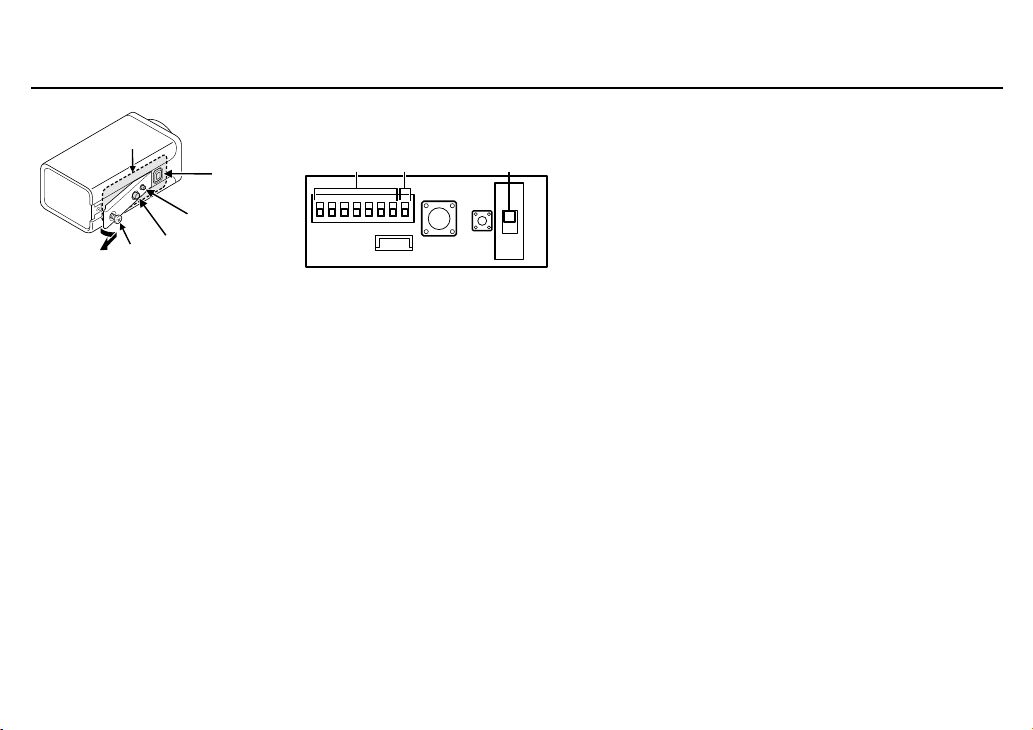
1 Power indicator (POWER)
Comes on when the power to the camera is on.
2 Video output connector (VIDEO OUT: BNC type)
5
Connect this connector to a device such as a VCR or monitor with a VIDEO IN connector.
3 24 V AC or 12 V DC input terminal (AC 24 V, DC 12 V, GND)
4 Remote control terminal (REMOTE, C, R)
5 RS-485 control push-lock terminal (RS485, G, B, A)
6 External sync composite video signal input connector (VBS IN: BNC type)
Connect to this connector the synchronizing signal output from a synchronizing signal device or the composite
signal of a video distributor.
7 Alarm output terminal (ALARM, C, A)
1
2
3
4
7
6
R: Remote input
C: Common
A: Twisted-pair cable terminal
B: Twisted-pair cable terminal
G: Ground terminal
A: Alarm
C: Common
4 English
Page 6
PARTS NAMES
8
9
F
G
A
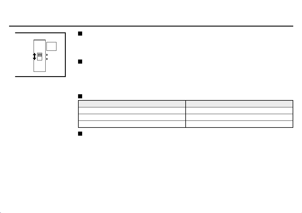
8 Camera setup section (under the cover)
To access the controls, loosen the cover fixing screw A, then remove the cover.
a b c
a Address setting switch (RS485 ADDRESS) . . . See page 57
b Terminater switch (TERMINATE) . . . . . . . . . . See page 57
c Auto iris lens switch (A. I. LENS) . . . . . . . . . . See page 7
9 Lens iris output connector (LENS)
This 4-pin connector is used to send the DC control signal and power supply to an auto-iris type lens.
F Menu setting button (SET)
Connect the camera to the monitor, then press the SET button for about 3 seconds to display the on-screen
menu.
G Cursor button (CURSOR)
j: Press this button to move the cursor up.
c: Press this button to move the cursor to the right, or to turn the settings ON/OFF etc.
d: Press this button to move the cursor to the left, or to turn the settings ON/OFF etc.
l: Press this button to move the cursor down.
English 5
Page 7
PARTS NAMES
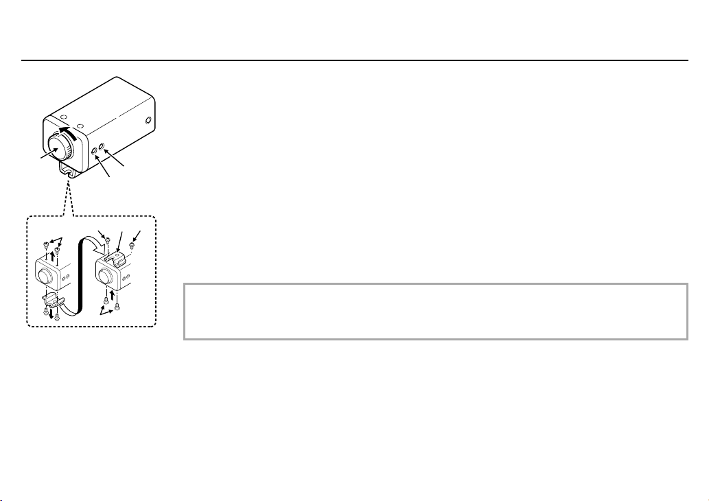
H Lens mount cap
The cap is installed to protect the lens mount section.
Remove the lens mount cap before installing a lens (sold separately).
I Flange-back adjustment screw (FLANGE BACK ADJ) (See page 9)
H
K
1
2
1
I
3
J
2
J Flange-back lock screw (FLANGE BACK LOCK)
K Camera installation bracket
The bracket can be fixed at the top or bottom of the camera. When fixing the bracket, be sure to use the
longer screws and install the shorter screws on the opposite side to seal the openings.
1 Shorter screws: M3 x 4
2 Longer screws: M3 x 6
3 Camera mounting screw hole: 1/4"-20 UNC
CAUTION:
When installing the camera bracket, select a location that can support the total weight of the
camera and accessories.
6 English
Page 8
CONCERNING AUTO-IRIS LENSES
DC type auto-iris lens
A. I.
LENS
DC
VIDEO
A lens without amplifier circuit that operates only on a DC power source. In general, this type of lens is
referred to as DC type coil lens or DC type non-amplifier lens.
(Set the A.I. LENS switch to the DC position.)
VIDEO type auto-iris lens
A lens with amplifier circuit that operates on video signal and DC power source. In general, this type of lens is
referred to as EE amplifier type lens.
ALC and LEVEL volume level controls are available on the lens for iris adjustments.
(Set the A.I. LENS switch to the VIDEO position.)
Compatible auto-iris lenses
1/3 inch Sanyo DC type lens VIDEO type lens
VCL-CS8LY: Standard angle, f= 8 mm Standard angle, f= 9 mm
VCL-CS4LY: Wide angle, f= 4 mm Telephoto angle, f= 12 mm
VCL-CS2LY: Ultra-wide angle, f= 2.8 mm Greater telephoto angle, f= 16 mm
If using a VIDEO type auto-iris lens
• Set the ALC and LEVEL controls on the lens to adjust the iris. Normally the ALC volume should be turned
all the way to Av (Average).
• Depending on the type of lens used, the lens may not perform properly. In such a case, adjust the LEVEL
volume on the lens casing to correct.
English 7
Page 9
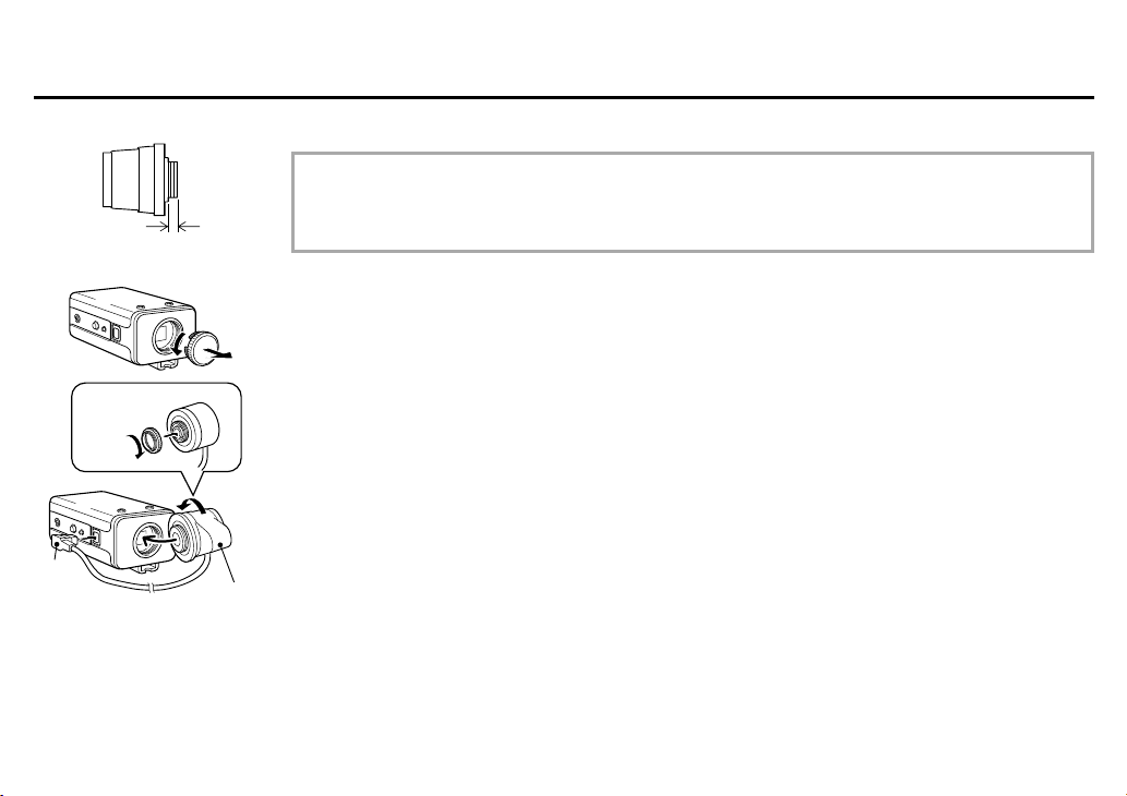
MOUNTING THE LENS
Please use a DC type auto-iris lens (sold separately).
Checking the lens mount
Do not use a lens if length “L” is more than 5 mm. If not, that may damage the camera and prevent
proper installation.
1 Remove the lens mount cap from the camera.
2 Install the auto-iris lens.
CS mount type lens
Carefully align the lens mount with the camera opening, then turn the lens slowly to install it.
C mount type lens
To allow for flange-back adjustment, install the supplied C-mount adaptor on the lens mount, then
carefully align the lens mount with the camera opening and turn the lens slowly to install it.
3 Connect the lens plug to the lens iris output connector (LENS) on the side of the camera.
When using lenses from other makers, the plug shape may not correspond to the terminal on the camera.
In such a case, remove the original plug and using a soldering iron, connect the supplied lens iris plug
according to the diagram. (Refer to page 9.)
C mount type lens
3
CS mount type lens
L
1
2
2
8 English
Page 10
MOUNTING THE LENS
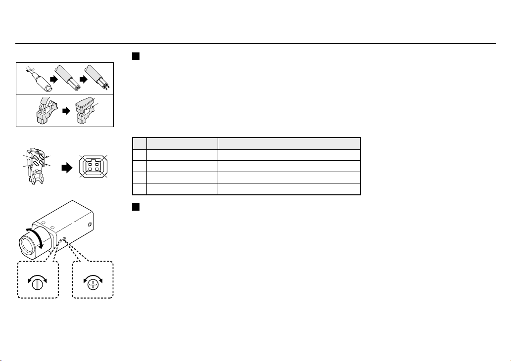
Rewiring the lens cable in the lens iris plug
1 Prepare the lens cable.
Cut the cable at the plug, then remove approx. 8 mm of the cable sheath and strip about 2 mm from each wire.
2 Install the lens iris plug.
Solder the cable to the pins following the correct pin layout (refer to the table and illustrations), then close
the plug cover.
Pin layout
1
3
DC type lenses VIDEO type lenses
Brake coil (–) +12 V DC (50 mA max.)
1
Brake coil (+) Not used
2
Drive coil (+) Video output (1.0 Vp-p, high impedance)
3
Drive coil (–) Ground (for video signal and DC power)
4
Flange-back adjustment
If the pick-up surface is not correctly positioned with relation to the lens focal point, the picture will be out of
focus (in particular when using auto-iris power zoom lenses, sold separately). If that is the case, adjust the
flange-back position as described below.
1 Using a + screwdriver, loosen the FLANGE BACK LOCK screw (M2:+).
2 Set the zoom lens to the maximum telephoto position, set the focus using the focus ring on the lens.
3 Set the zoom lens to the maximum wide angle position, set the focus using the FLANGE BACK ADJ. screw.
4 Repeat steps 2 and 3, until the image stays in focus when changing from a telephoto shot to a wide angle shot.
4
When the setting is complete, tighten the FLANGE BACK LOCK screw.
2
4
1
2
2
1
3
4
2
ADJ.
3
1
LOCK
English 9
Page 11
CONNECTIONS
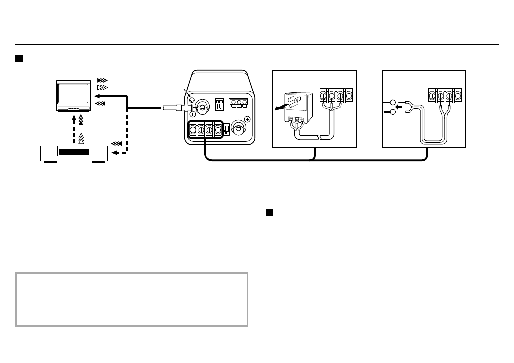
Basic connection for monitoring or recording
(Video signal connections)
: VIDEO IN
: VIDEO OUT
(A)
AC 24 V connection DC 12 V connection
Fig. 1 Fig. 2
AC24V
GND
DC12V
+
–
GND
DC12V
+ –
The peripheral devices (VCR, monitor, lens, etc.) and cables are
sold separately.
1 Make the video signal connection between the camera and
the monitor or timelapse VCR.
2 Power supply choices
• When using an AC 24 V power supply (UL listed class 2 power
supply), make the connections as indicated in Fig. 1.
• When using a DC 12 V power supply, make the connections as
indicated in Fig. 2.
CAUTION:
• To prevent camera and/or power supply failure, pay close
attention to polarity when making the connections.
• To prevent fire hazard any UL listed wire rated VW-1, should be
used for the 24 V AC cable input terminal.
3 Insert the plug of this power supply into a wall outlet.
The POWER indicator (A) will light. Adjust the picture on the
monitor using the Brightness and Contrast controls.
Coaxial cable type and maximum length
• Cable type RG-59U (3C-2V), 250 m maximum.
• Cable type RG-6U (5C-2V), 500 m maximum.
• Cable type RG-11U (7C-2V), 600 m maximum.
CAUTION:
• The RG-59U type cable should not be run through electrical
conduits or through the air.
• Use CCTV/Video-grade coaxial cable.
10 English
Page 12
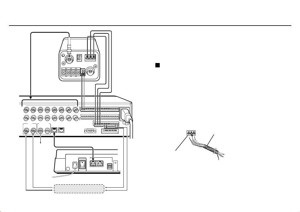
CONNECTIONS
CAMERA IN
terminal
ALARM input
terminal
9 10111213141516
MONITOR
VCR
IN OUT
Monitor
RS485
12AB
Multiplexer
Timelapse VCR
ALARM IN
123456789101112131415 16C
CABCALC
SENSOR ALARM
OUT
CONTROL
POWER
ON
12V DC IN
System controller
RS485
Before making any connection, make sure all the peripheral devices
are turned off.
Multiple units are connected in series using twisted-pair cables (bridge
connection). To set the addresses and make other fine adjustments,
please refer to page 57.
RS-485 terminal connections
Connect a shielded twisted-pair cable (AWG22) from signal A to
G
RS485
A
control
B
terminal
R1 R2CSW
C
GND
ABB
signal A, and from signal B to signal B of the RS485 control terminal
of each of the devices.
• Connection to a VCR
Make the connection between the RS485 (A, B, G) terminal on this
unit and the VCR RS485 A and B terminals and the C terminal.
• Connection to a multiplexer
Make the connection between the RS485 (A, B, G) terminal on this
unit and the multiplexer control terminals (A, B, C).
GBA
Push in to insert cable
Shielded twisted-pair cable
To A signal
To B signal
Ground
English 11
Page 13
CONNECTIONS
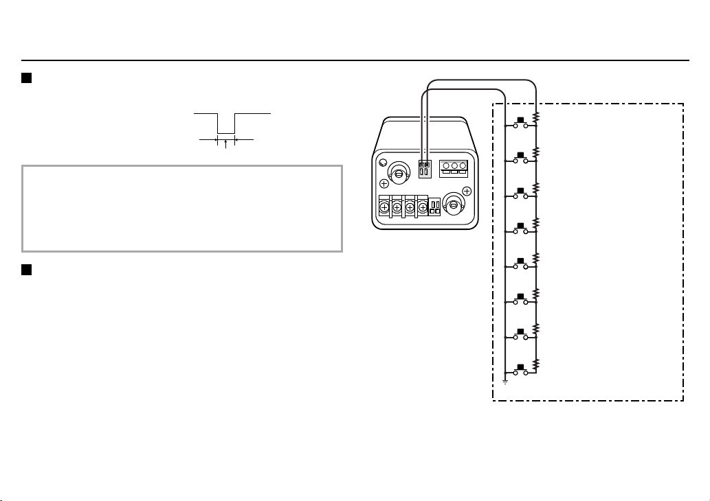
About the Alarm output terminal
Connect this unit to a VCR or a multiplexer.
Alarm output
A: Alarm signal output
C: Common
Alarm active
CAUTION:
• The digital processing of the settings may disturb the image for
a few seconds after the camera is turned on.
• While the menus are being set, noise sent on the lines by
peripheral devices may cause the settings to change. In such a
case, turn the power off then on again.
Remote controller circuit connections
Use the layout above to make a remote controller and make the
connections to the remote input pins (C, R) of the REMOTE terminal
as indicated. This will permit remote controlled operation of this unit.
(make contact LOW input)
Note:
• The maximum length of cable for remote controlled operation is
6 m (AWG 24).
• If the ZOOM item in the OPTION MENU is set to ON, remote
controlled zoom is possible even while the menu screens are
displayed.
5 V
About 500 msec.
CR
SW: switch
1.1kΩ
SW 1
: Electric PTZ
(pan-tilt-zoom) preset
0.68kΩ
SW 2
: Electric PTZ
(pan-tilt-zoom) OFF
0.91kΩ
: Zoom (wide)
SW 3
1.2kΩ
: Zoom (tele)
SW 4
1.8kΩ
: Panning (left)
SW 5
2.7kΩ
: Panning (right)
SW 6
3.9kΩ
: Tilting (upward)
SW 7
9.1kΩ
: Tilting (down)
SW 8
*
*Preset: will return to the zoom (pan,
tilt) center position.
12 English
Page 14
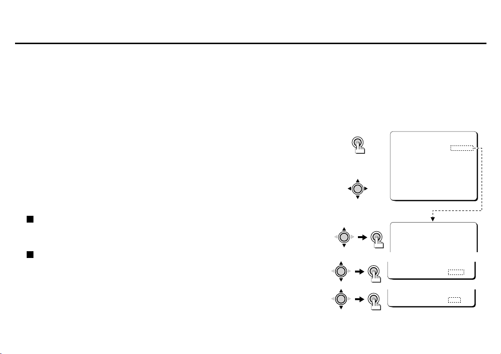
USING THE MENU SCREEN
This unit is set at the factory so that it can be used with a DC type auto-iris lens (sold separately).
Therefore, under normal conditions, additional settings or adjustments are not necessary.
Depending on the conditions of use, if settings or adjustments are required they can be done
from the “MAIN MENU” setting screen.
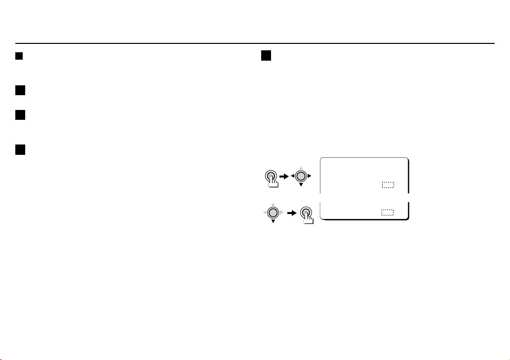
1 Press the SET button for about 3 seconds.
The MAIN MENU screen will be displayed.
2 Using the CURSOR button
1 Press the CURSOR (l) button to move the cursor down. When the cursor reaches the
bottom of the screen, it goes back up to the top of the screen.
2 Press the CURSOR (j) button to move the cursor up. When the cursor reaches the top
of the screen, it goes back down to the bottom of the screen.
3 Press the CURSOR (c) button to move the cursor to the right. This button is also used
to change ON/OFF settings etc.
4 Press the CURSOR (d) button to move the cursor to the left. This button is also used to
change ON/OFF settings etc.
Switching to sub-menu screens
Press the CURSOR (j, l, d or c) button until an item with a “c” next to it is flashing,
then press the SET button.
Switching to the MAIN MENU screen
Press the CURSOR (j or l) button to select BACK (it will flash), then press the SET button.
3 When finished:
Press the CURSOR (l) button to select END (it will flash), then press the SET button. The
display will return to the normal monitor screen.
4
SET
2
1
CURSOR
CURSOR
CURSOR
CURSOR
3
SET
SET
(Default setting)
MAIN MENU
LANGUAGE SET p
CAMERA ID OFF
SYNC INT
IRIS AI p
WHITE BALANCE ATW p
SHUTTER OFF
MOTION OFF
OPTION SET p
MENU END
(Example)
SET
LANGUAGE
LANGUAGE ENGLISH
LANGUE FRENCH
IDIOMA SPANISH
MENU BACK
MENU END
English 13
Page 15
USING THE MENU SCREEN
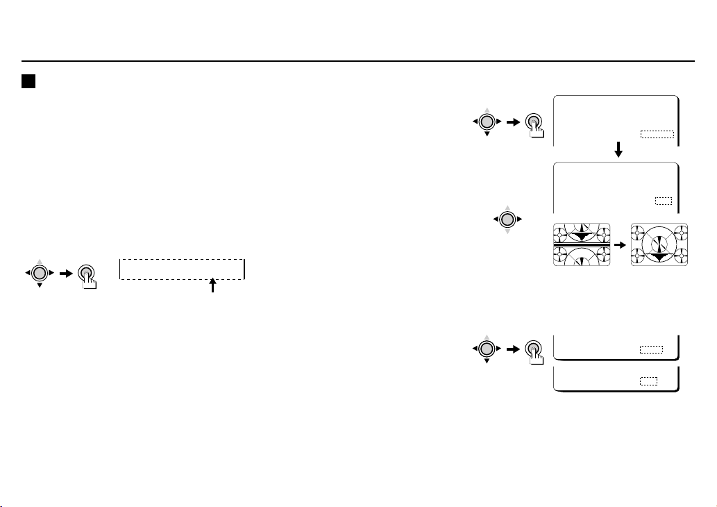
Notes concerning the menu settings
• Modes that cannot be used together
A) The IRIS item SENSE UP setting (other than OFF) and the MOTION item ON setting.
B) The SHUTTER item LONG setting and the MOTION item ON setting.
(X)
ADJUSTMENT FOR AI
LENS TYPE DC
BLC OFF
SENSE UP X2
MAIN MENU
LANGUAGE SET p
CAMERA ID OFF
SYNC INT
IRIS AI p
WHITE BALANCE ATW p
SHUTTER OFF
MOTION ON
MAIN MENU
LANGUAGE SET p
CAMERA ID OFF
SYNC INT
IRIS AI p
WHITE BALANCE ATW p
SHUTTER LONG
MAIN MENU
LANGUAGE SET p
CAMERA ID OFF
SYNC INT
IRIS AI p
WHITE BALANCE ATW p
SHUTTER OFF
MOTION ON
• When the IRIS item SENSE UP is used (setting other than OFF), the SHUTTER SPEED cannot be set. (Set either one to OFF in order to use the
other one.)
• If the SHUTTER item is set to LONG or SHORT and the IRIS AI or EI mode SENSE UP setting is used (setting other than OFF), the SHUTTER
item setting will be forced to OFF.
• The SHUTTER SPEED cannot be set if the IRIS item is set to EI mode. Switch the IRIS item setting to AI mode.
• When the OPTION MENU screen ZOOM or MIRROR items are being used, the following items setting screens will not be zoomed in or
mirrored.
☞ The BLC setting screen
☞ The ADJUSTMENT FOR MOTION screen SIZE and MASKING setting screens
☞ The WHITE BALANCE item ATW MASKING screen
• If the OPTION MENU screen AGC item is set to OFF and the IRIS mode SENSE UP setting is used (setting other than OFF), the AGC item
setting will be forced to ON.
(X)
14 English
Page 16
USING THE MENU SCREEN LANGUAGE
LANGUAGE setting
1 Press the SET button for about 3 seconds.
The MAIN MENU screen will be displayed.
2 Press the CURSOR (j or l) button until “SET” in the LANGUAGE item is selected,
then press the SET button.
The LANGUAGE screen will be displayed. The initial setting is English, but French and
Spanish can also be selected.
3 Select the desired language, then press the SET button.
The screen displays will change to the language selected.
4 When finished:
Press the CURSOR (l) button to select BACK (it will flash) at the bottom
of the screen. Then press the CURSOR (d or c) button to change BACK
to END, and press the SET button.
SET
CURSOR
CURSOR
MAIN MENU
LANGUAGE SET p
CAMERA ID OFF
SYNC INT
LANGUAGE
LANGUAGE ENGLISH
LANGUE FRENCH
IDIOMA SPANISH
LANGUE
SET
LANGUAGE ANGLAIS
LANGUE FRANCAIS
IDIOMA ESPAGNOL
IDIOMA
LANGUAGE INGLES
LANGUE FRANCES
IDIOMA ESPANOL
SET
MENU BACK
MENU END
English 15
Page 17
USING THE MENU SCREEN CAMERA ID
CAMERA ID setting
1 Press the SET button for about 3 seconds.
The MAIN MENU screen will be displayed.
2 Press the CURSOR (l, then d or c) button to change the CAMERA ID setting to
“ON”, then press the SET button.
The CAMERA ID SETTING screen will be displayed.
3 Example: To set the camera ID to “BN1”
The characters which have been selected will be displayed in the CAMERA ID IS
“????????” section.
1 Press the CURSOR (c) button until “B” is flashing, then press the SET button.
2 Press the CURSOR (l or d) button until “N” is flashing, then press the SET button.
3 Press the CURSOR (l or c) button until “1” is flashing, then press the SET button.
☞ Determining the start position for character input
Press the CURSOR (l) button until 2 is flashing, then press the CURSOR (d or c) button
until the 2 is pointing to the start position. Select the characters using the CURSOR buttons.
☞ Changing the camera ID to a new ID
Press the CURSOR (l, then d or c) button to change the PRESET setting to ON, then
press the SET button.
SET
CURSOR
CURSOR
CURSOR
CURSOR
MAIN MENU
LANGUAGE SET p
CAMERA ID ON p
SYNC INT
SET
CAMERA ID SETTING
ABCDEFGHIJKLM
NOPQRSTUVWXYZ
0123456789 :-
CAMERA ID IS ????????
SET
CAMERA ID IS BN1?????
SET
CAMERA ID IS ????????
SET
PRESET ON
OFF
16 English
Page 18
USING THE MENU SCREEN CAMERA ID
4 Press the CURSOR (l) button to select “SET” as the POSITION setting (the setting
will flash), then press the SET button.
The CAMERA ID SETTING screen will be displayed, and the set camera ID will flash at the
position currently set.
5 Press the CURSOR (d, c, j or l) button to determine the display position, then
press the SET button.
The display will return to the CAMERA ID SETTING screen.
NOTE: If the CAMERA ID is reset (using the menu PRESET setting), its position will also be
reset to the default position (right bottom corner).
6 When finished:
Press the CURSOR (l) button to select BACK (it will flash) at the bottom of the screen.
Then press the CURSOR (d or c) button to change BACK to END, and press the SET
button.
☞ To return to the previous screen, select BACK then press the SET button.
CURSOR
CURSOR
CURSOR
CAMERA ID SETTING
ABCDEFGHIJKLM
SET
NOPQRSTUVWXYZ
0123456789 :-
CAMERA ID IS BN1?????
POSITION SET p
SET
BN1
SET
MENU BACK
SET
MENU END
English 17
Page 19
USING THE MENU SCREEN SYNC/INT
SYNC settings
The following three types of synchronization settings can be carried
out.
A Internal synchronization (INT)
Generates a sync signal for internal camera use.
B Power supply synchronization (L - L: line-lock)
Matches the vertical sync signal for the camera with the
frequency of the AC power supply.
C External sync (VBS)
Matches the camera’s sync signal with the sync signal from an
external source.
A Internal synchronization setting (INT)
1 Press the SET button for about 3 seconds.
The MAIN MENU screen will be displayed.
2 Press the CURSOR (l, then d or c) button to change the
SYNC setting to “INT” (the setting will flash).
3 When finished:
Press the CURSOR (l) button until END is flashing at the bottom
of the screen, then press the SET button.
The display will return to the monitor screen.
SET
CURSOR
MAIN MENU
LANGUAGE SET p
CAMERA ID OFF
SYNC INT
SET
MENU END
18 English
Page 20
USING THE MENU SCREEN SYNC/L-L
B Power supply synchronization setting (L - L)
When using a camera switcher to connect 2 cameras or more to one monitor, there may be a
vertical roll of the images when switched. In such a case, set as described below.
1 Press the CURSOR (l, then d or c) button to change the SYNC setting to “L - L”
(the setting will flash), then press the SET button.
The ADJUSTMENT FOR L - L screen will be displayed.
2 Switch the display on the monitor from camera 1 to camera 2.
Press the CURSOR (d or c) button to adjust the vertical sync phase.
☞ Returning the value to the default setting
Press the CURSOR (l, then d or c) button to change the PRESET setting to ON, then
press the SET button.
CURSOR
SET
PRESET ON
OFF
3 When finished:
Press the CURSOR (l) button to select BACK (it will flash) at the bottom of the screen.
Then press the CURSOR (d or c) button to change BACK to END, and press the SET
button.
☞ To return to the previous screen, select BACK then press the SET button.
Note: Power supply synchronization setting is not possible when a 12 V DC power supply is
being used.
CURSOR
CURSOR
CURSOR
MAIN MENU
SET
LANGUAGE SET p
CAMERA ID OFF
SYNC L-L p
ADJUSTMENT FOR L-L
[V SYNC PHASE]
í--ú---z------ü 110
SET
MENU BACK
MENU END
English 19
Page 21
USING THE MENU SCREEN SYNC/VBS
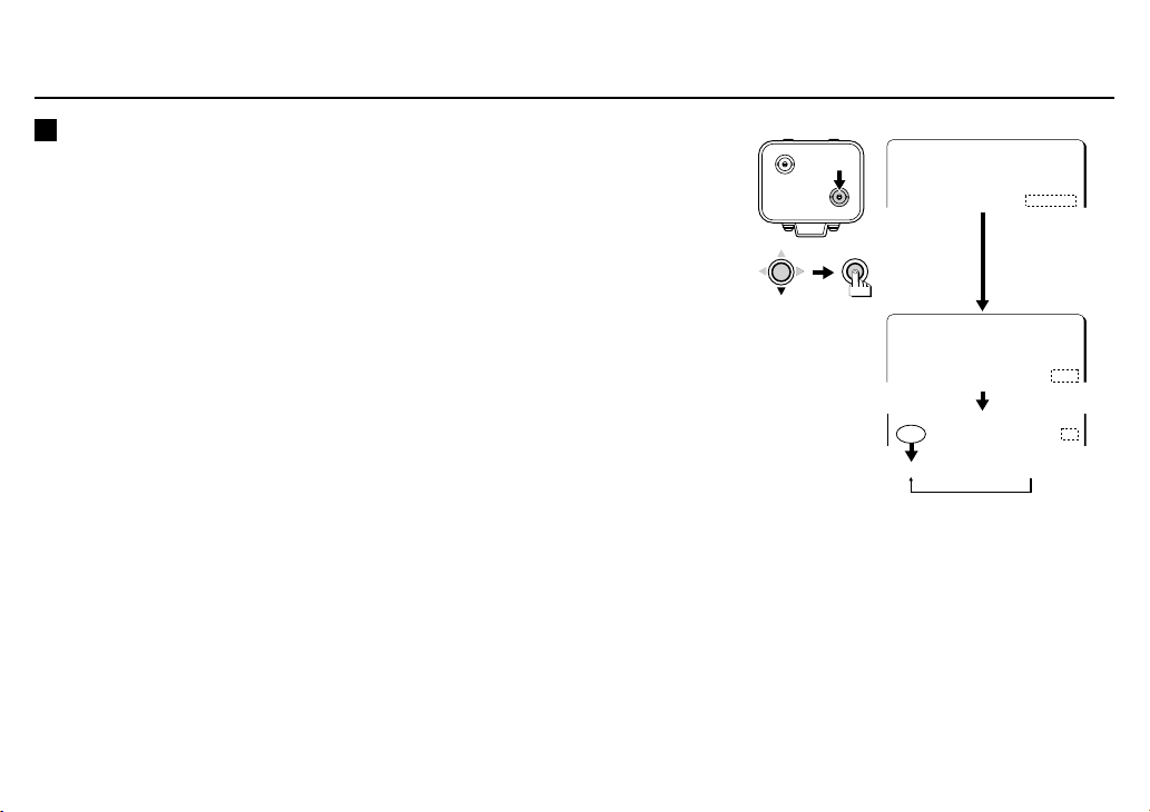
C External sync setting (VBS)
1 Connect the output signal from the other camera to the external sync input
connector of this camera.
The SYNC setting in the MAIN MENU screen will change to VBS.
2 Press the CURSOR (l) button to select the SYNC setting “VBS” (the setting will
flash), then press the SET button.
The ADJUSTMENT FOR VBS screen will be displayed.
3 The H (horizontal) value will flash. Press the CURSOR (d or c) button to adjust the
horizontal sync phase.
Note: If not using a camera (for the output signal), use a sync signal generator.
4 Press the CURSOR (l) button until the SC1 (sub-carrier) value is flashing, then press
the SET button to select the color phase (SC1 to SC4).
5 Press the CURSOR (d or c) button to make fine adjustments to the color phase.
☞ Returning the value to the default setting
Press the CURSOR (l, then d or c) button to change the PRESET setting to ON, then
press the SET button.
CURSOR
MAIN MENU
LANGUAGE SET p
CAMERA ID OFF
SYNC VBS p
SET
ADJUSTMENT FOR VBS
[PHASE]
H íú-----z------ü 32
SC1
ú------z------ü 1
SC1 ➞ SC2 ➞ SC3 ➞ SC4
20 English
Page 22

USING THE MENU SCREEN SYNC/VBS
6 When finished:
Press the CURSOR (l) button to select BACK (it will flash) at the bottom of the screen.
Then press the CURSOR (d or c) button to change BACK to END, and press the SET
button.
☞ To return to the previous screen, select BACK then press the SET button.
Note:
• If not using a camera to input the sync signal, use a sync signal generator, and input the
VBS signal from the sync signal generator to the external input. Settings such as INT in
the SYNC item will change automatically to VBS.
• When adjusting the horizontal sync phase, you must use an oscilloscope with a dual trace
function.
CURSOR
SET
MENU BACK
MENU END
English 21
Page 23

USING THE MENU SCREEN AI/BLC•LENS TYPE
IRIS setting
The following two types of iris level adjustment can be carried out.
A AI (Auto-Iris): This automatically adjusts the camera iris so that
the optimum image can be obtained when an
auto-iris lens is being used.
B EI (Electronic Iris): This method can be used for both a manual
iris or fixed iris lens. It automatically adjusts
the camera’s shutter speed so that an
optimum image can be obtained. (Refer to
page 27.)
A AI (Auto Iris) mode setting
1 Press the SET button for about 3 seconds.
The MAIN MENU screen will be displayed.
2 Press the CURSOR (l, then d or c) button to change the
IRIS setting to “AI” (the setting will flash), then press the SET
button.
The ADJUSTMENT FOR AI screen will be displayed.
LENS TYPE setting
The LENS TYPE setting will automatically change to the mode (DC or
VIDEO) which has been set using the auto-iris lens switch on the side
of the camera.
MAIN MENU
SET
CURSOR
LANGUAGE SET p
CAMERA ID OFF
SYNC INT
IRIS AI p
ADJUSTMENT FOR AI
LENS TYPE DC
BLC OFF
SENSE UP OFF
22 English
Page 24

USING THE MENU SCREEN AI/BLC•IRIS LEVEL
Adjust the IRIS LEVEL setting (DC type lens only)
Press the CURSOR (l) button so that the IRIS LEVEL value is flashing, then press the CURSOR
(d or c) button to adjust the IRIS LEVEL setting.
The larger the value, the greater the iris level.
☞ Returning the value to the default setting
Press the CURSOR (l, then d or c) button to change the PRESET setting to ON, then press
the SET button.
When finished:
Press the CURSOR (l) button to select BACK (it will flash) at the bottom of the screen. Then
press the CURSOR (d or c) button to change BACK to END, and press the SET button.
☞ To return to the previous screen, select BACK then press the SET button.
BLC setting
The following two types of BLC adjustment can be carried out
☞ MULTI (multi-spot photometry):
Brighter sections of the background are masked so that they do not affect photometry
detection. Brighter sections of the background are determined on-screen, and they are masked
so that they are in a position which do not affect the main subject (such as a person).
Note: If using a VIDEO type lens, the MULTI mode setting cannot be used.
☞ EVAL (5-section photometry):
Photometry and backlight correction are carried out so that the optimum image can be
obtained, even if the subject’s background is too bright.
CURSOR
CURSOR
ADJUSTMENT FOR AI
LENS TYPE DC
BLC OFF
SENSE UP OFF
[IRIS LEVEL]
í--ú---z------ü 30
SET
MENU BACK
MENU END
ADJUSTMENT FOR AI
LENS TYPE VIDEO
BLC EVAL p
OFF
English 23
Page 25

USING THE MENU SCREEN AI/BLC•MULTI
BLC/MULTI (multi-spot photometry) mode setting (DC type lens only)
1 Press the CURSOR (j, then d or c) button so that “MULTI” is selected for BLC (the
setting will flash), then press the SET button.
The BLC MASKING screen will be displayed. The mask cursor will also be flashing in the
top-left corner of the screen.
2 Press the CURSOR (d, c, j or l) button to move the mask cursor to the place
where photometry is not to be carried out, then press the SET button.
Continue pressing the CURSOR and SET buttons to apply masks to other areas. Masks can
be applied to a maximum of 32 separate sections (4 x 8).
Note:
• If you apply a mask to a wrong area by mistake, press the SET button once more to clear
the mask.
• When doing the MULTI setting, the dotted lines shown on the illustration are for clarity
only, they do not actually appear on-screen.
3 When all masks have been applied, press the CURSOR (l) button to move the mask
cursor to the bottom edge of the screen, and continue pressing the CURSOR button
for about 3 seconds.
☞ Returning to the default setting
Press the CURSOR (l, then d or c) button to change the PRESET setting to ON, then
press the SET button.
4 When finished:
Press the CURSOR (l) button to select BACK (it will flash) at the bottom of the screen.
Then press the CURSOR (d or c) button to change BACK to END, and press the SET
button.
☞ To return to the previous screen, select BACK then press the SET button.
CURSOR
CURSOR
CURSOR
ADJUSTMENT FOR AI
SET
LENS TYPE DC
BLC MULTIp
SENSE UP OFF
BLC MASKING
SET
CONT PRESS(2)
(Example)
SET
MENU BACK
MENU END
24 English
Page 26

USING THE MENU SCREEN AI/BLC•EVAL
BLC/EVAL (5-section photometry) mode setting
1 Press the CURSOR (j, then d or c) button so that “EVAL” is selected for BLC (the
setting will flash), then press the SET button.
The ADJUSTMENT FOR BLC screen will be displayed, and the photometry mask will also be
displayed in the center of the screen.
2 Press the CURSOR (d, c, j or l) button to move (up, down, right, left) the
photometry area to the desired position, then press the SET button.
The SIZE screen will be displayed.
3 Press the CURSOR (d, c, j or l) button to change the size of the photometry
area, then press the SET button.
The BLC WINDOW WEIGHTING screen will be displayed.
Note: When the OPTION MENU screen ZOOM or MIRROR item is being used (set to ON),
the BLC (MULTI or EVAL) setting screen will not be zoomed in or mirrored.
BLC WINDOW WEIGHTING
TOP 0
BOTTOM 0
LEFT 0
RIGHT 0
CENTER[FIX] 15
PRESET OFF
MENU BACK
CURSOR
CURSOR
ADJUSTMENT FOR AI
SET
LENS TYPE DC
BLC EVAL p
SENSE UP OFF
ADJUSTMENT FOR BLC
SET
[POSITION]
ADJUSTMENT FOR BLC
[SIZE]
English 25
Page 27

USING THE MENU SCREEN AI/BLC•EVAL
4 Press the CURSOR (l) button to select the photometry areas (TOP, etc.), and press
the CURSOR (d or c) button to set the weighting (numeric value setting).
☞ Weighting
• Setting is possible within the range of 0 to 15.
• If set to 0, the light intensity will be ignored, and if set to 15, the light intensity will be
measured with no adjustment.
BLC WINDOW WEIGHTING
TOP 0
CURSOR
BOTTOM 0
LEFT 0
RIGHT 0
CENTER[FIX] 15
PRESET OFF
MENU BACK
Note:
• If using a VIDEO type lens, the center and the edges will each be divided into separate sections
so that the weighting for the edges can be set. The larger the value, the more backlight
correction is done for that area.
• When using a VIDEO type lens, the ADJUSTMENT FOR BLC (SIZE) setting will be larger than
for a DC type lens.
• The ALC volume on the lens should be turned all the way to Av (Average).
• If the backlight correction function does not compensate properly for the conditions, correct
using the LEVEL volume on the lens.
☞ Returning the values to the default settings
Press the CURSOR (l, then d or c) button to change the PRESET setting to ON, then press the
SET button.
5 When finished:
Press the CURSOR (l) button to select BACK (it will flash) at the bottom of the screen.
Then press the SET button. The ADJUSTMENT FOR AI screen will be displayed.
BLC WINDOW WEIGHTING
TOP 0
BOTTOM 0
LEFT 0
RIGHT 0
CENTER[FIX] 15
PRESET OFF
MENU BACK
BLC WINDOW WEIGHTING
TOP 0
BOTTOM 0
LEFT 0
RIGHT 0
CENTER[FIX] 15
PRESET OFF
MENU BACK
BLC WINDOW WEIGHTING
TOP 0
BOTTOM 0
LEFT 0
RIGHT 0
CENTER[FIX] 15
PRESET OFF
MENU BACK
BLC WINDOW WEIGHTING
TOP 0
BOTTOM 0
LEFT 0
RIGHT 0
CENTER[FIX] 15
PRESET OFF
MENU BACK
ADJUSTMENT FOR BLC
[BLC LEVEL]
í------ú------ü 8
26 English
Page 28

USING THE MENU SCREEN AI/SENSE UP•EI
SENSE UP setting
Press the CURSOR (l) button so that the SENSE UP setting is at OFF
and is flashing, then press the CURSOR (d or c) button to set the
exposure time.
The basic exposure time is 1/60 second (SENSE UP set to OFF), and
the setting can be changed to X2, X4, X8, X16 or X32.
Note:
• When the MOTION item is set to ON, the SENSE UP setting is not
possible.
• When filming moving subjects, the higher the SENSE UP setting
(sensitivity), the more pronounced afterimage will be visible. Also,
when the sensitivity is high, white dots will be visible on the screen,
this is due to the CCD characteristics.
CURSOR
ADJUSTMENT FOR AI
LENS TYPE DC
BLC OFF
SENSE UP OFF
OFF➞X2➞X4➞X8➞X16➞X32
B EI (Electronic Iris) mode setting
The EI mode setting is the same as for the AI mode setting with a DC
type lens, please refer to page 22.
1 Press the CURSOR (l, then d or c) button until “EI” in the
IRIS item is flashing, then press the SET button.
The ADJUSTMENT FOR EI screen will be displayed.
2 Press the CURSOR (l, then d or c) button to select MULTI or
EVAL for the BLC (backlight correction) setting.
Note:
• When the electronic iris function captures a very bright subject (such as a
light, etc.), the quantity of light entering the lens cannot be adjusted, and
image smearing and other conditions may appear. In such a case, this can
be prevented by changing the lighting angle or using an auto-iris lens.
• The EI mode setting is used for indoors only.
• If the camera location lighting if fluorescent, it will be scattered by the
subject. To prevent this, it is recommended to change to incandescent
lighting.
MAIN MENU
SET
LANGUAGE SET p
CAMERA ID OFF
SYNC INT
IRIS EI p
ADJUSTMENT FOR EI
BLC EVAL
SENSE UP OFF
SET
MULTI
OFF
p
p
English 27
Page 29

USING THE MENU SCREEN WHITE BALANCE/ATW
WHITE BALANCE setting
The following three types of white balance adjustment can be carried
out.
A Automatic color temperature tracking (ATW: Auto Trace
White balance)
This makes adjustments automatically so that the same colors can
be obtained even if the illumination level changes.
B Push-lock white balance (AWC: Auto White balance Control)
One-push automatic white balance setting is possible. This is used
mainly when the ATW setting does not reproduce faithful colors.
Refer to page 31.
C Manual white balance (MWB)
This lets you make fine adjustments to the color as desired. It can
be used when the optimum color reproduction cannot be
obtained by using ATW. Refer to page 32.
A Automatic color temperature tracking setting
(ATW)
1 Press the SET button for about 3 seconds.
The MAIN MENU screen will be displayed.
2 Press the CURSOR (l, then d or c) button to change the
WHITE BALANCE setting to “ATW” (the setting will flash).
3 When finished:
Press the CURSOR (l) button to select BACK (it will flash) at the
bottom of the screen. Then press the CURSOR (d or c) button to
change BACK to END, and press the SET button.
☞ To return to the previous screen, select BACK then press
the SET button.
SET
CURSOR
CURSOR
MAIN MENU
LANGUAGE SET p
CAMERA ID OFF
SYNC INT
IRIS AI p
WHITE BALANCE ATW p
SET
MENU BACK
MENU END
28 English
Page 30

USING THE MENU SCREEN WHITE BALANCE/ATW•MASKING
If there is a bright light source appearing on the screen, it may interfere with the white
balance setting. In such cases, use the MASKING setting function to mask excessively
bright areas so that they are not detected.
MASKING setting
1 Press the CURSOR (l, then d or c) button to change the WHITE BALANCE setting
to “ATW” (the setting will flash), then press the SET button.
The ADJUSTMENT FOR ATW screen will be displayed.
2 Press the CURSOR (d or c) button to change the MASKING setting to “ON” (the
setting will flash), then press the SET button.
The ATW MASKING screen will be displayed, and the mask cursor will flash in the top-left
corner of the screen.
3 Press the CURSOR (d, c, j or l) button to move the mask cursor to the place where
color temperature tracking is not to be carried out, then press the SET button.
Continue pressing the CURSOR and SET buttons to apply masks to other areas. Masks can
be applied to a maximum of 32 separate sections (4 x 8).
Note:
• If you apply a mask to a wrong area by mistake, press the SET button once more to clear the
mask.
• When the OPTION MENU screen ZOOM or MIRROR items are being used (set to ON), the
MASKING item setting screen will not be zoomed in or mirrored.
• The MASKING settings will also apply to the AWC mode.
• The dotted lines shown on the illustration are for clarity only, they do not actually appear
on-screen.
CURSOR
CURSOR
SET
ADJUSTMENT FOR ATW
MASKING ON p
ATW MASKING
SET
CONT PRESS(2)
(Example)
English 29
Page 31

USING THE MENU SCREEN WHITE BALANCE/ATW•MASKING
4 When all masks have been applied, press the CURSOR (l) button to move the mask
cursor to the bottom edge of the screen, and continue pressing the CURSOR button
for about 3 seconds.
☞ Returning to the default setting
Press the CURSOR (l, then d or c) button to change the PRESET setting to ON, then
press the SET button.
5 When finished:
Press the CURSOR (l) button to select BACK (it will flash) at the bottom of the screen. Then
press the CURSOR (d or c) button to change BACK to END, and press the SET button.
☞ To return to the previous screen, select BACK then press the SET button.
CURSOR
SET
MENU BACK
MENU END
30 English
Page 32

USING THE MENU SCREEN WHITE BALANCE/AWC
B Push-lock white balance adjustment (AWC)
1 Press the CURSOR (l, then d or c) button to change the WHITE BALANCE setting
to “AWC” (the setting will flash), then press the SET button.
The ADJUSTMENT FOR AWC screen will be displayed.
2 Press and hold the SET button.
While the SET button is pressed, LOCK will light steadily, and white balance adjustment
begins. When you release the SET button, adjustment will stop and LOCK will begin
flashing.
3 To make fine adjustments to the tint, press the CURSOR (l) button to select the
GO TO MWB setting “SET” (the setting will flash), then press the SET button.
The ADJUSTMENT FOR MWB screen will then be displayed. Refer to the manual white
balance (MWB) adjustment procedure for details on how to adjust this setting.
☞ Returning to the default setting
Press the CURSOR (l, then d or c) button to change the PRESET setting to ON, then
press the SET button.
4 When finished:
Press the CURSOR (l) button to select BACK (it will flash) at the bottom of the screen.
Then press the CURSOR (d or c) button to change BACK to END, and press the SET
button.
☞ To return to the previous screen, select BACK then press the SET button.
CURSOR
CURSOR
CURSOR
CURSOR
SET
MAIN MENU
LANGUAGE SET p
CAMERA ID OFF
SYNC INT
IRIS AI p
WHITE BALANCE AWC p
ADJUSTMENT FOR AWC
SET
AWC LOCK LOCK
GO TO MWB SET p
ADJUSTMENT FOR AWC
SET
AWC LOCK LOCK
GO TO MWB SET p
ADJUSTMENT FOR MWB
[OFFSET]
R í--ú---z------ü 64
B í--ú---z------ü 64
SET
MENU BACK
MENU END
English 31
Page 33

USING THE MENU SCREEN WHITE BALANCE/MWB
C Manual white balance setting (MWB)
1 Press the CURSOR (l, then d or c) button to change the WHITE BALANCE setting
to “MWB” (the setting will flash), then press the SET button.
The ADJUSTMENT FOR MWB screen will be displayed.
2 Press the CURSOR (l, then d or c) button to adjust the tint for the red (R) and
blue (B) colors.
A setting towards the right will make the tint (Red or Blue) stronger.
☞ Returning to the default setting
Press the CURSOR (l, then d or c) button to change the PRESET setting to ON, then
press the SET button.
3 When finished:
Press the CURSOR (l) button to select BACK (it will flash) at the bottom of the screen.
Then press the CURSOR (d or c) button to change BACK to END, and press the SET
button.
☞ To return to the previous screen, select BACK then press the SET button.
CURSOR
CURSOR
SET
MAIN MENU
LANGUAGE SET p
CAMERA ID OFF
SYNC INT
IRIS AI p
WHITE BALANCE MWB p
ADJUSTMENT FOR MWB
[OFFSET]
R í--ú---z------ü 64
B í--ú---z------ü 64
SET
MENU BACK
MENU END
32 English
Page 34

USING THE MENU SCREEN SHUTTER/SHORT
Electronic SHUTTER setting
The following two types of shutter speed functions are available.
A Short mode (SHORT):
This shortens the exposure time so that you can film subjects
which are moving quickly.
B Long exposure mode (LONG):
This is used for making dark scenes lighter, such as when filming
at nighttime.
Note:
• The shutter speed can only be set when IRIS has been set to AI
mode (manual iris or fixed iris lens).
• When the SENSE UP setting is used (setting other than OFF), the
SHUTTER SPEED cannot be set. Also, the SHUTTER item setting
will be forced to OFF.
English 33
Page 35

USING THE MENU SCREEN SHUTTER/SHORT
A For SHORT mode
1 Press the SET button for about 3 seconds.
The MAIN MENU screen will be displayed.
2 Press the CURSOR (l, then d or c) button to change the SHUTTER setting to
“SHORT” (the setting will flash), then press the SET button.
The ADJUSTMENT FOR ES screen will be displayed.
3 Press the CURSOR (d or c) button to change the shutter speed.
☞ Returning to the default setting
Press the CURSOR (l, then d or c) button to change the PRESET setting to ON, then
press the SET button.
4 When finished:
Press the CURSOR (l) button to select BACK (it will flash) at the bottom of the screen.
Then press the CURSOR (d or c) button to change BACK to END, and press the SET
button.
☞ To return to the previous screen, select BACK then press the SET button.
CURSOR
CURSOR
CURSOR
MAIN MENU
LANGUAGE SET p
SET
CAMERA ID OFF
SYNC INT
IRIS AI p
WHITE BALANCE ATW p
SHUTTER SHORTp
ADJUSTMENT FOR ES
SHUTTER SPEED 60
60 ➞ 100 ➞ 250 ➞ 500 ➞ 1000
10000 4000 2000
SET
MENU BACK
MENU END
34 English
Page 36

USING THE MENU SCREEN SHUTTER/LONG
B For LONG mode
1 Press the CURSOR (l, then d or c) button to change the SHUTTER setting to
“LONG” (the setting will flash), then press the SET button.
The ADJUSTMENT FOR ES screen will be displayed.
2 Press the CURSOR (d or c) button to change the shutter speed.
☞ Returning to the default setting
Press the CURSOR (l, then d or c) button to change the PRESET setting to ON, then
press the SET button.
3 When finished:
Press the CURSOR (l) button to select BACK (it will flash) at the bottom of the screen.
Then press the CURSOR (d or c) button to change BACK to END, and press the SET
button.
☞ To return to the previous screen, select BACK then press the SET button.
Note:
• When MOTION is set to ON, LONG mode cannot be selected.
• When filming moving subjects, the higher the SHUTTER SPEED setting (acceleration),
the more pronounced afterimage will be visible. Also, when the acceleration is high,
white dots will be visible on the screen, this is due to the CCD characteristics.
• When the SENSE UP setting is used (setting other than OFF), the SHUTTER SPEED
cannot be set. Also, the SHUTTER item setting will be forced to OFF.
CURSOR
CURSOR
CURSOR
MAIN MENU
LANGUAGE SET p
SET
CAMERA ID OFF
SYNC INT
IRIS AI p
WHITE BALANCE ATW p
SHUTTER LONG p
ADJUSTMENT FOR ES
SHUTTER SPEED X1
X1 ➞ X2 ➞ X4 ➞ X8 ➞ X16 ➞ X32
SET
MENU BACK
MENU END
English 35
Page 37

USING THE MENU SCREEN MOTION
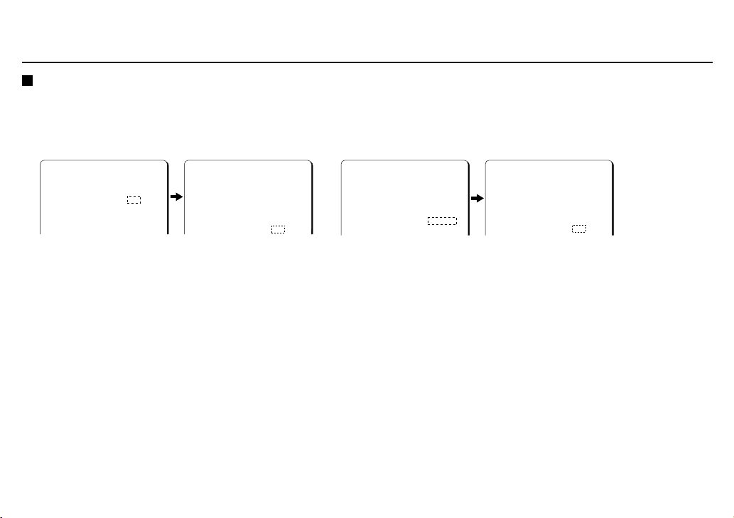
MOTION setting
For the MOTION setting, the screen area is split up into 64 (8 X 8)
detection areas where movements (or changes) are detected.
Then, using the SENSITIVITY and other menu settings, these
movements can be set to trigger alarms. With these menu settings,
you can set the MOTION setting to detect only the motions you
require for your situation.
Though, the initial settings will provide adequate detection of
movement, alarms may be triggered by motions that are normal and
should be ignored. To customize the MOTION setting for your
situation, use the MASKING, SENSITIVITY, and other menu settings.
For more details regarding the MOTION operation, refer to the
examples given on page 46.
Note: MOTION settings are not possible if either of the following
settings have been made:
☞ The IRIS (SENSE UP) mode has been set. (Refer to page 27.)
☞ The SHUTTER (LONG) mode has been set. (Refer to page 35.)
Note:
• When the MOTION default setting is OFF, movements will not be
detected and alarms triggers will not be output.
• When doing the MOTION settings, the dotted lines and the mask
shown on the illustrations are for clarity only, they do not actually
appear on-screen.
• An alarm is output when all the parameters set for ADJUSTMENT
FOR MOTION items are met.
CURSOR
(Example)
No movement sensed onscreen.
MAIN MENU
LANGUAGE SET p
SET
CAMERA ID OFF
SYNC INT
IRIS AI p
WHITE BALANCE ATW p
SHUTTER OFF
MOTION OFF
The detection is done
according to the
movement and changes
sensed in these areas.
A moving subject is
detected.
ON p
36 English
Page 38

USING THE MENU SCREEN MOTION
The following settings can be made from the MOTION menu.
Operating direction detection function (DIRECTION):
A
Sets the camera to detect only movement in a certain direction.
B Size setting function (SIZE):
Sets the size of the objects to be detected when movement is
being detected.
C Mask area setting function (MASKING):
Sets a mask for places where movement is not to be detected.
D Sensitivity setting function (SENSITIVITY):
Sets the amount of sensitivity for parameters such as movement,
level, light difference and time interval.
E Continuous electronic zoom function for movement
detection (ZOOM):
When a doubtful movement is detected, the zoom ratio is set to
X2 and any further movement is tracked.
F Alarm interval setting function (INTERVAL):
Sets the amount of time for no output when an alarm is received.
G Alarm signal setting function (ALARM SIGN):
Causes the camera ID to flash when an alarm signal is detected.
English 37
Note:
• If the whole background is empty, detection may not be performed
properly.
• If the camera is subjected to vibration, incorrect detection may
happen.
• Adjusting each item to the optimum setting will improve detection,
however there will always be situations where incorrect detection
or no detection happens.
• This unit is not desined for theft or fire prevention. No guarantee is
given against any accident or damage that may occur.
Page 39

USING THE MENU SCREEN MOTION/DIRECTION
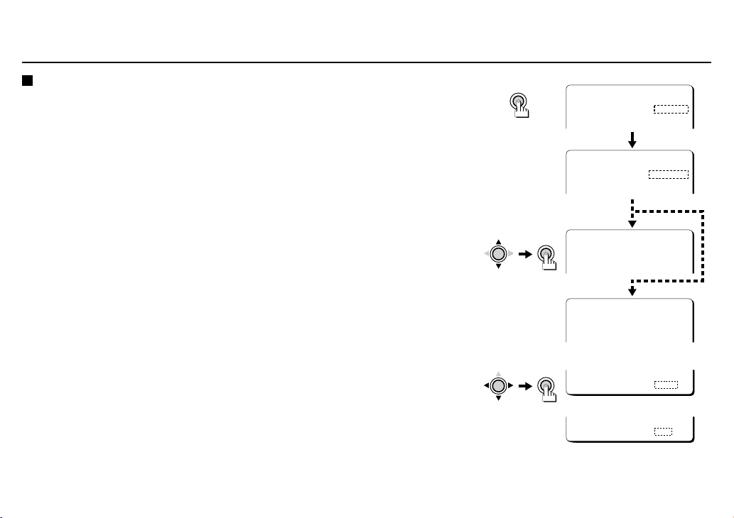
1 Press the SET button for about 3 seconds.
The MAIN MENU screen will be displayed.
2 Press the CURSOR (l, then d or c) button to change the
MOTION setting to “ON” (the setting will flash), then press
the SET button.
The ADJUSTMENT FOR MOTION screen will be displayed.
SET
CURSOR
MAIN MENU
LANGUAGE SET p
CAMERA ID OFF
SYNC INT
IRIS AI p
WHITE BALANCE ATW p
SHUTTER OFF
MOTION ON p
SET
ADJUSTMENT FOR MOTION
DIRECTION OFF
SIZE SET p
MASKING OFF
SENSITIVITY SET p
ZOOM OFF
INTERVAL 5S
ALARM SIGN OFF
PRESET OFF
MENU BACK
A DIRECTION setting
Press the CURSOR (j or l) button to select the DIRECTION setting
OFF (the setting will flash), then press the CURSOR (d or c) button
repeatedly.
The following display will appear. Detection is carried out in the
direction indicated by the arrow only.
OFF: Any movement is detected, regardless of the direction
üü: Toward the right
íí: Toward the left
óó: Upward
ññ: Downward
ADJUSTMENT FOR MOTION
CURSOR
DIRECTION OFF
üü, íí, óó, ññ
38 English
Page 40

USING THE MENU SCREEN MOTION/SIZE
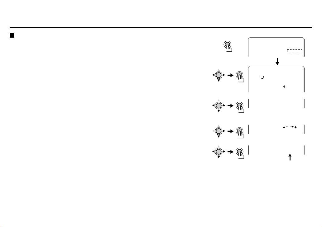
B SIZE setting
The SIZE setting will split the screen area in 64 (8 x 8) squares and
the detection is made by measuring movement and changes in each
of the squares. To set the size of the subjects to detect, it is
necessary to set the number of squares where detection should
happen simultaneously.
The MOTION SIZE setting lets you decide the size of subjects to
detect by setting the number of contiguous squares in both
directions (horizontal and vertical) where movement should be
sensed simultaneously before an alarm trigger is output.
Fig. 1
SIZE setting Subject
V H Size A B C D
21
11
12
31
Example: The illustrated four types of moving subjects (A, B, C, D) will be sensed and an alarm
trigger will be output or not, as shown in Fig.1, depending on the SIZE setting.
❍: An alarm is output
✕: No alarm is output
1 Press the CURSOR (l) button to select the SIZE setting “SET” (the setting will flash),
then press the SET button.
The MOTION SIZE screen will be displayed.
2 The V (vertical) value is flashing, then press the CURSOR (c) button.
The size area will increase in the vertical direction, and the numeric value will also increase.
Press the CURSOR (d) button to decrease the size.
3 Press the CURSOR (l) button so that the H (horizontal) value is flashing, then press
the CURSOR (c) button.
The size area will increase in the horizontal direction, and the numeric value will also
increase. Press the CURSOR (d) button to decrease the size.
CURSOR
(A)
(B)
SET
CURSOR
CURSOR
(Example)
ADJUSTMENT FOR MOTION
DIRECTION OFF
SIZE SET p
MOTION SIZE
V 2
H 1
MOTION SIZE
V 2
H 1
(C)
(D)
English 39
Page 41

USING THE MENU SCREEN MOTION/SIZE
MOTION SIZE display table
V 1, H 1 V 2, H 1 V 3, H 1
V 3, H 2 V 2, H 4 V 1, H 2 V 1, H 3 V 1, H 8
V 3, H 3 V 4, H 2
V 8, H 1 V 2, H 2
☞ Returning to the default setting
Press the CURSOR (l, then d or c) button to change the PRESET setting to ON, then
press the SET button.
4 When finished.
Press the CURSOR (l) button to select BACK (it will flash) at the bottom of the screen.
Then press the CURSOR (d or c) button to change BACK to END, and press the SET
button.
Note:
• If you set the area to a value greater than 8, the value will change back automatically to
a value of 8 or less. The size area will be displayed on the screen for reference, but it will
not necessarily be in the correct position.
• When the OPTION MENU screen ZOOM or MIRROR item is being used (set to ON), the
ADJUSTMENT FOR MOTION screen SIZE and MASKING items setting screens will not
be zoomed in or mirrored.
• If the MOTION SIZE setting is used, the backlight correction will not operate with a
VIDEO type lens.
CURSOR
V 2, H 3
SET
MENU BACK
MENU END
40 English
Page 42

USING THE MENU SCREEN MOTION/MASKING
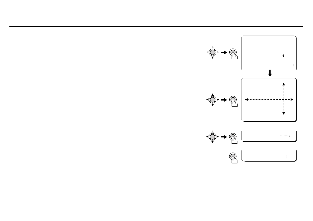
C MASKING setting
1 Press the CURSOR (l, then d or c) button to set MASKING to “ON” (the setting
will flash), then press the SET button.
The MOTION MASKING screen will be displayed, and the mask cursor will flash in the
top-left corner of the screen.
2 Press the CURSOR (d, c, j or l) button to move the mask cursor to the place
where movement is not to be detected, then press the SET button.
The position of the mask cursor will be fixed, and the area will increase each time the
CURSOR button is pressed. Press the CURSOR button repeatedly to set the masking area.
Masks can be applied to a maximum of 64 separate sections (8 x 8).
Note: If you apply a mask to a wrong area by mistake, press the SET button once more to
clear the mask.
3 When the mask has been applied, press the CURSOR (l) button to move the mask
cursor to the bottom edge of the screen, and continue pressing the CURSOR button
for about 3 seconds.
☞ Returning to the default setting
Press the CURSOR (l, then d or c) button to change the PRESET setting to ON, then
press the SET button.
CURSOR
CURSOR
SET
ADJUSTMENT FOR MOTION
DIRECTION OFF
SIZE SET p
MASKING ON p
MOTION MASKING
SET
CONT PRESS(ñ)
(Example)
English 41
Page 43

USING THE MENU SCREEN MOTION/MASKING
4 When finished:
Press the CURSOR (l) button to select BACK (it will flash) at the bottom of the screen.
Then press the CURSOR (d or c) button to change BACK to END, and press the SET
button.
☞ To return to the previous screen, select BACK then press the SET button.
Note:
• When the OPTION MENU screen ZOOM or MIRROR item is being used (set to ON), the
ADJUSTMENT FOR MOTION screen SIZE and MASKING items setting screens will not
be zoomed in or mirrored.
• If the MASKING setting is used, the backlight correction will not operate with a VIDEO
type lens.
CURSOR
SET
MENU BACK
MENU END
42 English
Page 44

USING THE MENU SCREEN MOTION/SENSITIVITY
D SENSITIVITY setting
The smaller the setting value, the greater the sensitivity.
Press the CURSOR (l) button to select the SENSITIVITY setting “SET” (the setting will flash),
then press the SET button.
The SENSITIVITY screen will be displayed.
MOVE
This sets the movement amplitude of subjects on the screen.
Press the CURSOR (d or c) button so that the MOVE value is flashing. (Maximum: 6)
Set the value to a large to avoid detecting slight movement such as movement caused by the wind.
Y-LEVEL
This sets the brightness level. Any signal darker that the set brightness will be ignored.
This is mainly used to avoid incorrect detection caused by electronic noise in a dark
picture.
Press the CURSOR (l, then d or c) button so that the Y-LEVEL value is flashing. (Maximum: 10)
Set the value to a large to avoid incorrect detection of movement caused by electronic noise
from a dark picture.
Y-DIFFER
This sets the brightness change level. A lower setting will ignore bigger changes in the
brightness.
Press the CURSOR (l, then d or c) button so that the Y-DIFFER value is flashing.
(Maximum: 10)
This allows movement to be detected when there are variations in brightness. Set the value to a
large if lights being turned on and off are not to be detected.
CURSOR
CURSOR
SET
ADJUSTMENT FOR MOTION
DIRECTION OFF
SIZE SET p
MASKING ON p
SENSITIVITY SET p
SENSITIVITY
SET
MOVE í---ú----ü 3
Y-LEVEL í-ú------ü 3
Y-DIFFER í------ú-ü 8
DURATION ú--------ü 1
English 43
Page 45

USING THE MENU SCREEN MOTION/ZOOM, INTERVAL
DURATION
This sets how long the moving subject should be on the screen before it is detected. A
lower setting will set a longer on screen duration before the subject is detected.
Press the CURSOR (l, then d or c) button so that the DURATION value is flashing. (Maximum: 60)
Set the value to a large if objects which are moving fast are not to be detected.
Each setting step represents 1/12 of a second. The maximum on-screen duration that can be
set is 5 seconds (1/12 x 60).
☞ Returning to the default setting
Press the CURSOR (l, then d or c) button to change the PRESET setting to ON, then press
the SET button.
Note: If all the settings values are too large, alarm triggering may not operate as desired.
☞ When finished:
Press the CURSOR (l) button to select BACK (it will flash) at the bottom of the screen. Then
press the CURSOR (d or c) button to change BACK to END, and press the SET button.
☞ To return to the previous screen, select BACK then press the SET button.
E ZOOM setting
Press the CURSOR (j, then d or c) button to select the ZOOM setting OFF (the setting will
flash), then press the CURSOR button repeatedly.
The length of time for zoom display will be displayed. When a doubtful movement is detected,
the moving object is followed at a zoom ratio of X2.
Note: The higher the SENSITIVITY screen DURATION item setting is, the longer it will take
for the movement to be tracked. To track all movements set the DURATION to 1.
CURSOR
SET
CURSOR
MENU BACK
ADJUSTMENT FOR MOTION
DIRECTION OFF
SIZE SET p
MASKING OFF
SENSITIVITY SET p
ZOOM OFF
OFF➞5S➞10S➞20S➞30S➞60S
44 English
Page 46

USING THE MENU SCREEN MOTION/INTERVAL, ALARM SIGN
F INTERVAL setting
Press the CURSOR (l) button so that the INTERVAL value is flashing, then press the CURSOR
(d or c) button repeatedly.
After an alarm signal has been output once, this sets the length of time that no further alarm
signal is output when movement is detected.
G ALARM SIGN setting
Press the CURSOR (l, then d or c) button to change the ALARM SIGN setting to “ON” or
“OFF”.
OFF: No alarm display appears
ON: The camera ID flashes when movement is detected.
Note: If the camera ID display is not turned on, the camera ID which has been set in the
CAMERA ID SETTING screen will flash. The length of time that the camera ID flashes is
the same as the length of time for the alarm ignore time (INTERVAL) setting.
When finished
Press the CURSOR (l) button to select BACK (it will flash) at the bottom of the screen. Then
press the CURSOR (d or c) button to change BACK to END, and press the SET button.
☞ To return to the previous screen, select BACK then press the SET button.
☞ Returning to the default setting
Press the CURSOR (l, then d or c) button to change the PRESET setting to ON, then press
the SET button.
CURSOR
CURSOR
CURSOR
ADJUSTMENT FOR MOTION
DIRECTION OFF
SIZE SET p
MASKING OFF
SENSITIVITY SET p
ZOOM OFF p
INTERVAL 5S
5S➞10S➞15S➞20S➞30S
5M 4M 3M 2M 1M
ADJUSTMENT FOR MOTION
DIRECTION OFF
SIZE SET p
MASKING OFF
SENSITIVITY SET p
ZOOM OFF p
INTERVAL 5S
ALARM SIGN ON
????????
SET
MENU BACK
MENU END
English 45
Page 47

USING THE MENU SCREEN MOTION/EXAMPLE
Motion detector setting example
After the camera has been connected to the peripheral devices (VCR, multiplexer, etc.) set the
MOTION item to send an alarm trigger to the peripheral devices when the set movement
parameters are met.
Checking the detected movements set by the MOTION item
If the MOTION item settings are not made properly, the desired results will not be obtained. To test
for correct detection, please proceed as follows.
There are two setting checking methods, using the ADJUSTMENT FOR MOTION screen ZOOM or
ALARM SIGN.
A) The image is zoomed in when a movement is detected
Set the ZOOM item to 5S. When the motion detector senses a movement from a subject on the
screen, the image is zoomed in.
B) The camera ID flashes on-screen when a movement is detected
Set the ALARM SIGN item to ON, then exit the menu screen. When the motion detector senses
a movement from a subject on the screen, the camera ID is displayed on-screen.
Note: The camera ID will not be displayed while a menu is displayed on-screen.
CAMERA 1
46 English
Page 48

USING THE MENU SCREEN MOTION/EXAMPLE
DIRECTION setting
Select the desired direction arrows (ex.: íí). The detection will be done when the subject moves in
the direction of the arrows. For example, the setting can be done in order to detect a subject
entering a room, but ignored when it is going out of the room.
DIRECTION
SIZE setting
From the SIZE SET item switch to the MOTION SIZE screen. This setting allows you to set the area
covered before detection is done.
The default setting is 2 squares (1 horizontally, 2 vertically). Each square corresponds to 1/64 of the
screen area (there are 64 (8 x 8) squares on the screen). The default setting will detect a movement
that is sensed in 2 squares simultaneously.
Note:
• If set to 1 square, the detection rate will be the highest, any slight movement being detected.
• If set to 2 squares or more, movement must be detected simultaneously in all the squares, the
detection rate will therefore be lower.
MASKING setting
Switch from the MASKING screen to the MOTION MASKING screen. In this screen, using a black
mask, you can mask movements of subjects (like the swaying of a tree, or light flickering on the
monitor screen) that should not be detected.
English 47
MOTION SIZE
V 2
H 1
MOTION SIZE
V 2
H 2
Active
Active
Page 49

USING THE MENU SCREEN MOTION/EXAMPLE
SENSITIVITY setting
From the SENSITIVITY SET item switch to the SENSITIVITY screen. In this screen, the sensitivity level setting will be higher towards the left and
lower towards the right.
Note: If all the settings values are too large, alarm triggering may not operate as desired.
• MOVE
For a small movement such as a tree swaying, that should not be
detected, make a setting towards the right.
SENSITIVITY
MOVE í---ú----ü 3
CURSOR
• Y-DIFFER
If lights are turned on and off causing brightness changes that
should not be detected, make a setting towards the right.
SENSITIVITY
CURSOR
Y-DIFFERí------ú-ü 8
• Y-LEVEL
In a dark location, if electronic noise causes detection, make a
setting towards the right.
Brightness
No detection
Noise
Time
SENSITIVITY
Y-LEVEL í-ú------ü 3
CURSOR
• DURATION
If fast moving objects such as cars that should not be detected
will cross the screen, make a setting towards the right.
SENSITIVITY
CURSOR
DURATIONú--------ü 1
48 English
Page 50

USING THE MENU SCREEN OPTION
OPTION settings
The following settings can be made from the OPTION menu.
A APERTURE setting:
This adjustment is used when you would like to correct outlines.
B AGC setting:
This automatically amplifies the image signal when filming in
slightly dark places so that the picture becomes brighter.
C GAMMA setting:
The GAMMA characteristics can be set to “1” or “0.45”.
D ZOOM setting:
A fixed mode and a variable mode are available. In fixed mode,
the zoom ratios are set to X2, X4 and X8. In variable mode, the
zoom ratio can be changed smoothly. Pan and tilt operations are
also available.
E MIRROR setting
The image can be rotated horizontally then vertically or vertically
then horizontally.
F RS-485 setting
You can set the communication parameters.
G INITIAL setting:
This returns all settings to the factory default settings (initial
values).
1 Press the SET button for about 3 seconds.
The MAIN MENU screen will be displayed.
2 Press the CURSOR (l) button to select the OPTION setting
“SET” (the setting will flash), and then press the SET button.
The OPTION MENU screen will be displayed.
SET
CURSOR
MAIN MENU
LANGUAGE SET p
CAMERA ID OFF
SYNC INT
IRIS AI p
WHITE BALANCE ATW p
SHUTTER OFF
MOTION ON
OPTION SET p
SET
OPTION MENU
APERTURE ON
AGC ON
GAMMA ON
ZOOM OFF
MIRROR OFF
RS-485 SET
INITIAL OFF
MENU BACK
p
p
English 49
Page 51

USING THE MENU SCREEN OPTION/APERTURE
A APERTURE setting
1 Press the CURSOR (d or c) button to change the APERTURE setting to “ON” (the
setting will flash), then press the SET button.
The ADJUSTMENT FOR APERTURE screen will be displayed.
2 Press the CURSOR (d or c) button so that the H (horizontal) value flashes, then
correct the outlines in the horizontal direction.
As the value increases, the correction amount increases.
3 Press the CURSOR (l, then d or c) button so that the V (vertical) value flashes,
then correct the outlines in the vertical direction.
As the value increases, the correction amount increases.
☞ Returning the values to the default settings
Press the CURSOR (l, then d or c) button to change the PRESET setting to ON, then
press the SET button.
4 When finished:
Press the CURSOR (l) button to select BACK (it will flash) at the bottom of the screen.
Then press the CURSOR (d or c) button to change BACK to END, and press the SET
button.
☞ To return to the previous screen, select BACK then press the SET button.
CURSOR
CURSOR
SET
OPTION MENU
APERTURE ON
ADJUSTMENT FOR APERTURE
H í---ú--z------ü 6
V í------z-ú----ü 9
SET
MENU BACK
MENU END
p
50 English
Page 52

USING THE MENU SCREEN OPTION/AGC, GAMMA
B AGC setting
1 Press the CURSOR (l, then d or c) button to change the AGC setting to ON or
OFF (the setting will flash).
2 When finished:
Press the CURSOR (l) button to select BACK (it will flash) at the bottom of the screen.
Then press the CURSOR (d or c) button to change BACK to END, and press the SET
button.
☞ To return to the previous screen, select BACK then press the SET button.
Note: If the item AGC is set to OFF when the SENSE UP item is set to ON, the item AGC
setting will be forced to ON.
C GAMMA setting
1 Press the CURSOR (l, then d or c) button to change the GAMMA setting to ON or
OFF (the setting will flash).
ON: 0, 45
OFF: 1
2 When finished:
Press the CURSOR (l) button to select BACK (it will flash) at the bottom of the screen.
Then press the CURSOR (d or c) button to change BACK to END, and press the SET
button.
☞ To return to the previous screen, select BACK then press the SET button.
CURSOR
CURSOR
CURSOR
CURSOR
SET
OPTION MENU
APERTURE ON p
AGC ON
SET
MENU BACK
MENU END
SET
OPTION MENU
APERTURE ON p
AGC ON
GAMMA ON
SET
MENU BACK
MENU END
English 51
Page 53

USING THE MENU SCREEN OPTION/FIXI ZOOM, PAN
D ZOOM setting
1 Press the CURSOR (l, then d or c) button to change the ZOOM setting to “ON”
(the setting will flash), then press the SET button.
The ZOOM screen will be displayed.
The ADJUSTMENT FOR ZOOM screen will be displayed.
2 Press the CURSOR (d or c) button to select either FIX (fixed) or VAR (variable).
For FIX mode
1) Press the CURSOR (d or c) button to select “FIX” as the MODE setting.
X2 will appear automatically for ZOOM.
2) Press the CURSOR (l) button, then press the CURSOR (d or c) button repeatedly.
The image and the zoom ratio will change together (X2, X4 or X8).
PANNING:
• Press the CURSOR (l) button to select the PAN setting “LEFT” (the setting will flash), then
press and hold the SET button. The picture will pan toward the left.
• Press the CURSOR (c) button to select the PAN setting “RIGHT” (the setting will flash),
then press and hold the SET button. The picture will pan toward the right.
CURSOR
CURSOR
CURSOR
OPTION MENU
SET
APERTURE ON
AGC ON
GAMMA ON
ZOOM ON
ADJUSTMENT FOR ZOOM
SET
MODE FIX
ZOOM X2
PAN LEFT RIGHT
TILT UP DOWN
SET
PAN LEFT RIGHT
p
p
52 English
Page 54

USING THE MENU SCREEN OPTION/FIXI TILT
TILTING:
• Press the CURSOR (l) button to select the TILT setting “UP” (the setting will flash), then
press and hold the SET button. The picture will tilt upward.
• Press the CURSOR (c) button to select the TILT setting “DOWN” (the setting will flash),
then press and hold the SET button. The picture will tilt downward.
☞ Returning to the default settings
Press the CURSOR (l, then d or c) button to change the PRESET setting to ON, then
press the SET button.
3) When finished:
Press the CURSOR (l) button to select BACK (it will flash) at the bottom of the screen.
Then press the CURSOR (d or c) button to change BACK to END, and press the SET
button.
☞ To return to the previous screen, select BACK then press the SET button.
CURSOR
CURSOR
SET
TILT UP DOWN
SET
MENU BACK
MENU END
English 53
Page 55

USING THE MENU SCREEN OPTION/VAR ZOOM, PAN
For VAR mode
Press the CURSOR (d or c) button to select “VAR” as the MODE setting.
WIDE and TELE will appear automatically for ZOOM.
ZOOMING:
• Press the CURSOR (l) button to select the ZOOM setting “WIDE” (the setting will flash),
then press and hold the SET button. The screen will switch to WIDE mode.
• Press the CURSOR (c) button to select the ZOOM setting “TELE” (the setting will flash),
then press and hold the SET button. The screen will switch to ZOOM mode.
PANNING:
• Press the CURSOR (l) button to select the PAN setting “LEFT” (the setting will flash), then
press and hold the SET button. The picture will pan to the left.
• Press the CURSOR (c) button to select the PAN setting “RIGHT” (the setting will flash),
then press and hold the SET button. The picture will pan to the right.
CURSOR
CURSOR
CURSOR
SET
SET
ADJUSTMENT FOR ZOOM
MODE VAR
ZOOM WIDE TELE
PAN LEFT RIGHT
TILT UP DOWN
ZOOM WIDE TELE
PAN LEFT RIGHT
54 English
Page 56

USING THE MENU SCREEN OPTION/VAR ZOOM, TILT
TILTING:
• Press the CURSOR (l) button to select the TILT setting “UP” (the setting will flash), then
press and hold the SET button. The picture will tilt upward.
• Press the CURSOR (c) button to select the TILT setting “DOWN” (the setting will flash),
then press and hold the SET button. The picture will tilt downward.
☞ Returning the values to the default settings
Press the CURSOR (l, then d or c) button to change the PRESET setting to ON, then
press the SET button.
When finished:
Press the CURSOR (l) button to select BACK (it will flash) at the bottom of the screen. Then
press the CURSOR (d or c) button to change BACK to END, and press the SET button.
☞ To return to the previous screen, select BACK then press the SET button.
Note:
• The maximum zoom ratio in VAR mode is the current zoom ratio setting in FIX mode.
• When ZOOM in the OPTION MENU has been set to ON, the PAN and TILT settings will
automatically change to the settings which were last made.
If the ZOOM item in the OPTION MENU is set to “ON”, while a normal screen is
displayed, simply press the CURSOR buttons for pan and tilt operations.
Note:
• This will operate if a setting (5S to 5M) is made for the ZOOM item in the ADJUSTMENT FOR
MOTION menu. If a subject movement is detected and the ZOOM function operates (the pan
and tilt operations being also included), the CURSOR buttons manual pan and tilt operations will
not be possible.
• The ZOOM function enlarges a portion of the image, resulting in a lower on-screen resolution.
CURSOR
CURSOR
SET
TILT UP DOWN
SET
MENU BACK
MENU END
English 55
Page 57

USING THE MENU SCREEN OPTION/MIRROR, RS-485
E MIRROR setting
1 Press the CURSOR (l, then d or c) button to change the MIRROR setting to “H”
(the setting will flash).
The image will be inverted horizontally. The image will change as described below each time
the CURSOR button is pressed.
• OFF: Normal image • V: Inverted vertically
• H: Inverted horizontally • HV: Inverted horizontally and vertically
2 When finished:
Press the CURSOR (l) button to select BACK (it will flash) at the bottom of the
screen. Then press the CURSOR (d or c) button to change BACK to END, and
press the SET button.
☞ To return to the previous screen, select BACK then press the SET button.
F RS-485 setting
1 Press the CURSOR (l) button to select the RS-485 setting “SET” (the setting will
flash), then press the SET button. The MENU FOR RS-485 screen will be displayed.
2 Press the CURSOR (l) button so that the BAUD RATE value is flashing, then press
the CURSOR (d or c) button to change the communication speed.
Note: The BAUD RATE setting should be compatible with the transmission speed of the
peripheral devices.
3 Press the CURSOR (l, then d or c) button to change the ALARM setting to ON
(the setting will flash), then set the alarm transmission.
ON: Alarm signals are sent to the controller
OFF: Alarm signals are not sent to the controller
CURSOR
OFF H V HV
CURSOR
CURSOR
CURSOR
OPTION MENU
APERTURE ON
AGC ON
GAMMA ON
ZOOM OFF
MIRROR H
SET
MENU BACK
MENU END
OPTION MENU
SET
APERTURE ON
AGC ON
GAMMA ON
ZOOM OFF
MIRROR OFF
RS-485 SET p
MENU FOR RS-485
SET
BAUD RATE 19200
ALARM ON
19200➞9600➞4800➞2400
p
p
OFF
56 English
Page 58

USING THE MENU SCREEN OPTION/RS-485
ADDRESS setting
If the ADDRESS setting on the screen is 0, this means that the camera’s RS-485 address is
currently set to 0. If the address is changed using the address setting switches at the side of the
camera as shown in the illustration, the new address will be displayed on the screen.
TERMINATE setting
The DIP switches need to be set when a computer, special controller, etc. connected to the
RS-485 connectors is used to control the camera. Make sure to turn the camera power off
before setting the DIP switches.
About SW No.
1-7: To setup the camera address (only when using the RS-485 connector).
Switch 1 is the least significant bit (LSB) and switch 7 the most significant bit (MSB) (Down: 0,
Up: 1). This setting is done according to a binary code.
8: To setup the termination (only when using the RS-485 connector).
OFF side (down): Not terminated
ON side (up): Terminated
☞ Returning the values to the default settings
Press the CURSOR (l, then d or c) button to change the PRESET setting to ON, then press
the SET button.
When finished
Press the CURSOR (l) button to select BACK (it will flash) at the bottom of the screen. Then
press the CURSOR (d or c) button to change BACK to END, and press the SET button.
☞ To return to the previous screen, select BACK then press the SET button.
CURSOR
(ADDRESS SET)
ON
ON
12345678
OFF
CURSOR
MENU FOR RS-485
SET
BAUD RATE 19200
ALARM ON
ADDRESS 0
SET
MENU BACK
MENU END
TERMINATER ON/OFF
English 57
Page 59

USING THE MENU SCREEN OPTION/INITIAL
G INITIAL setting
This lets you return all settings to the factory defaults.
1 Press the CURSOR (l, then d or c) button to set INITIAL to “ON” then press the
SET button.
If ON is selected, WAITING will flash underneath the word ON, then all settings will be
returned to the factory defaults.
2 When finished:
Press the CURSOR (l) button to select BACK (it will flash) at the bottom of the screen.
Then press the CURSOR (d or c) button to change BACK to END, and press the SET
button.
☞ To return to the previous screen, select BACK then press the SET button.
CURSOR
CURSOR
SET
ON
WAITING
SET
OPTION MENU
APERTURE ON
AGC ON
GAMMA ON
ZOOM OFF
MIRROR OFF
RS-485 SET
INITIAL ON
WAITING
MENU BACK
MENU BACK
MENU END
p
p
58 English
Page 60

OPERATIONS USING THE SYSTEM CONTROLLER
Operations using the camera MENU screens
1 Press the INDIVIDUAL button.
2 Press the MODE button to select CM.
3 Use the numeric buttons to enter the address (camera).
4 Press the ENTER button to accept the address.
5 Press the MENU button.
The MAIN MENU screen will be displayed.
Note:
• The CURSOR buttons on the camera correspond to the J, q, s
and t buttons on the controller.
• The SET button on the camera corresponds to the ENTER button
on the controller.
21
MAIN MENU
LANGUAGE SET p
CAMERA ID OFF
SYNC INT
IRIS AI p
WHITE BALANCE ATW p
SHUTTER OFF
MOTION OFF
OPTION SET p
MENU END
43
English 59
Page 61

OPERATIONS USING THE SYSTEM CONTROLLER
Operations using the camera command
(CAMERA) button
1 Press the INDIVIDUAL button.
2 Press the MODE button to select CM.
3 Use the numeric buttons to enter the address (camera).
4 Press the ENTER button to accept the address, then use the
command buttons for subsequent operations.
A: Electronic zoom
1) Zoom (T, W) operations
Press the ZOOM (T) or ZOOM (W) button.
2) Setting and clearing zoom mode
• Press the ZOOM PRESET button then press the “–” button.
The zoom mode will be set and electronic zoom will be canceled.
• Press the ZOOM PRESET button once more then press the “+”
button.
Electronic zoom mode will be set.
3) Pan and tilt operations (operation in normal screen mode)
If the electronic zoom mode is set to ON, press the J (q, s or
t) button. The focus will return to the center of the screen when
the 0 button is pressed.
B: Iris level operations
If using a DC-type auto-iris lens, the iris opening can be controlled. If
using a video-type or manual-type auto-iris lens, no operation can be
carried out.
1) Lens iris opening
Press the IRIS+ button to open the iris, and press the IRIS– button
to close the iris.
2) Returning the iris to the initial opening setting
Press the IRIS+ and IRIS– buttons simultaneously.
3) Error information when using a video-type auto-iris lens or
when the camera iris setting is EI mode
An Error display will appear on the menu screen of the controller.
B
EDC
21
43A
60 English
Page 62

OPERATIONS USING THE SYSTEM CONTROLLER
C: Setting the SENSE UP and electronic shutter
1) If the SHUTTER setting in the camera’s main menu is set to
LONG or SHORT, you can change the SHUTTER SPEED setting.
• Press the ELS button, then press the “+” button to turn on the
electronic shutter.
• Press the ELS button, then press the “–” button to turn off the
electronic shutter.
2) If the SHUTTER setting in the camera’s main menu is set to
OFF, you can change the SENSE UP setting.
• Press the ELS button, then press the “+” button to turn on the
SENSE UP setting.
• Press the ELS button, then press the “–” button to turn off the
SENSE UP setting.
Note:
• If the SENSE UP zoom ratio setting has not been changed, then
the zoom ratio will be set to the factory default setting, which is
X8.
• If the MOTION setting is at ON, the electronic sensitivity (SENSE
UP) will not operate.
• If the SHUTTER item SHORT and LONG settings default values
have not been changed, the SHORT setting will be 1/100S and
the LONG setting will be X8.
D: Backlight correction settings
1) Turning backlight correction on
Press the BLC button then press the “+” button.
2) Turning backlight correction off
Press the BLC button then press the “–” button.
If the BLC setting has not been changed, then the mode will be
set to EVAL mode when the backlight correction is turned on.
E: White balance and AWC-LOCK settings
1) White balance lock
Press the AWC SET button.
2) Returning to the white balance mode previously active
Press the AWC RESET button.
English 61
Page 63

MENU DISPLAY
1
4321
MAIN MENU
LANGUAGE SET p
CAMERA ID OFF
SYNC INT
IRIS AI p
WHITE BALANCE ATW p
SHUTTER OFF
MOTION OFF
OPTION SET p
MENU END
5678
See page 63
LANGUAGE
LANGUAGE
LANGUAGE ENGLISH
LANGUE FRENCH
IDIOMA SPANISH
3
SYNC ADJUSTMENT
INT
4
IRIS ADJUSTMENT
AI p
EI p
L-L p
VBS p
DC type
VIDEO type
2
CAMERA ID SETTING
OFF
ON p
ADJUSTMENT FOR L-L
[V SYNC PHASE]
í--ú---z------ü 110
ADJUSTMENT FOR VBS
[PHASE]
H íú-----z------ü 32
SC1ú------z------ü 1
ADJUSTMENT FOR AI
LENS TYPE DC
BLC OFF
SENSE UP OFF
[IRIS LEVEL]
í--ú---z------ü 30
ADJUSTMENT FOR AI
LENS TYPE VIDEO
BLC OFF
SENSE UP OFF
CAMERA ID SETTING
ABCDEFGHIJKLM
NOPQRSTUVWXYZ
0123456789 :-
CAMERA ID IS ????????
POSITION SET p
OFF
OFF
OFF
OFF
MULTIp
EVAL p
X2, X4, X8,
X16, X32
EVAL p
X2, X4, X8,
X16, X32
????????
BLC MASKING
ADJUSTMENT FOR BLC
[POSITION]
ADJUSTMENT FOR BLC
[POSITION]
BLC WINDOW WEIGHTING
TOP 0
BOTTOM 0
LEFT 0
RIGHT 0
CENTER[FIX] 15
ADJUSTMENT FOR BLC
[SIZE]
ADJUSTMENT FOR BLC
[SIZE]
ADJUSTMENT FOR EI
BLC OFF
SENSE UP OFF
Same as ADJUSTMENT FOR AI
ADJUSTMENT FOR BLC
[BLC LEVEL]
í------ú------ü 8
62 English
Page 64

MENU DISPLAY
5
WHITE BALANCE SETTING
ATW p
AWC p
MWB p
7
8
English 63
ADJUSTMENT FOR ATW
MASKING OFF
ADJUSTMENT FOR AWC
AWC LOCK LOCK
GO TO MWB SET p
MOTION DETECTER
OFF
ON p
OPTION MENU
SET p
OPTION MENU
APERTURE ON p
AGC ON
GAMMA ON
ZOOM OFF
MIRROR OFF
RS-485 SET p
INITIAL OFF
MENU BACK
ADJUSTMENT FOR MOTION
DIRECTION OFF
SIZE SET p
MASKING OFF
SENSITIVITY SET p
ZOOM OFF
INTERVAL 5S
ALARM SIGN OFF
OFF
ADJUSTMENT FOR MWB
[OFFSET]
MWB
R í--ú---z------ü 64
B í--ú---z------ü 64
ON p OFF
ADJUSTMENT FOR APERTURE
H í----ú-z------ü 6
V í------zú-----ü 9
ON OFF
ON OFF
ON p OFF
OFF
OFF ON
WAITING
ON p
H, V, HV
ATW MASKING
OFF
ADJUSTMENT FOR ZOOM
MODE FIX
ZOOM X2
PAN LEFT RIGHT
TILT UP DOWN
6
ELECTRIC SHUTTER (IRIS MODE : AI only)
OFF
OFF ON p
OFF
5S, 10S, 15S, 20S, 30S, 1M, 2M 3M, 4M, 5M
OFF ON
FIX
VAR
X2
5S, 10S, 20S, 30S, 60S
ADJUSTMENT FOR ZOOM
MODE VAR
ZOOM WIDE TELE
PAN LEFT RIGHT
TILT UP DOWN
X4, X8
SHORTp
LONG p
MENU FOR RS-485
BAUD RATE 19200
ALARM ON
ADDRESS 0
ADJUSTMENT FOR ES
SHUTTER SPEED 60
ADJUSTMENT FOR ES
SHUTTER SPEED X1
MOTION SIZE
V 2
H 1
MOTION MASKING
SENSITIVITY
MOVE í---ú----ü 3
Y-LEVEL í-ú------ü 3
Y-DIFFER í------ú-ü 8
DURATION ú--------ü 1
19200
ON OFF
60, 100, 250, 500,
1000, 2000, 4000
10000
X1, X2, X4, X8,
X16, X32
9600, 4800, 2400
Page 65

TROUBLESHOOTING
Before taking the camera for repairs, please check below to make sure that the camera is used correctly. If it still does not perform correctly, please
consult your dealer or a Sanyo Authorized Service Center.
No picture on the monitor screen
• Is the power turned on to all connected devices? Is the voltage correct?
• Are all the signal connecting cables correctly connected?
• Is the lighting sufficient?
• Has the lens cap been removed?
• Is the lens type (DC or VIDEO) correctly selected?
Depending on the type of lens, the A. I. LENS switch must be set accordingly.
• Is the iris control correctly set?
A: When using a DC type lens, the LEVEL volume (inside the camera casing) should be adjusted.
B: When using a VIDEO type lens, the LEVEL volume (on the lens) should be adjusted.
The picture is not clear
• Is the monitor correctly adjusted?
• Is the flange-back position correctly set?
• Is the lens focus correctly adjusted?
• Are the lens surfaces clean?
If there is dust or finger prints on the lens, the image quality will deteriorate. To clean the lens use a soft cloth or a commercially available lens
cleaning set.
SERVICE
This camera is a precision instruments and if treated with care, will provide years of satisfactory performance. However, in the event of a problem,
the owner is advised not to attempt to make repairs or open the cabinet. Servicing should always be referred to your dealer or Sanyo Authorized
Service Center.
64 English
Page 66

SPECIFICATIONS
Camera:
Scanning system
Interlace
Image device
Picture elements
Effective picture elements
Synchronizing system
Resolution
Video output level
Video S/N ratio
Minimum required
illumination
(incandescent lighting)
Backlight compensation
Iris function
Electronic iris range
Flange-back
White balance
: NTSC standard TV system (525 TV lines,
30 frames/sec.)
: PLL 2:1 interlace
: 1/3 inch solid state image device CCD
: 811 (H) x 508 (V)
: 768 (H) x 494 (V)
: Internal sync, Line lock sync switchable,
External sync
: 470 TV lines horizontally, 350 TV lines
vertically
: 1.0 Vp-p/75 ohms, composite
: More than 48 dB
: Approx. 0.05 lux with a F 1.2 lens (32X
electronic sensitivity),
Approx. 1.4 lux with a F 1.2 lens (normal
mode)
: ON/OFF setting, Multi-zone light
measuring system (Active when using
an auto-iris lens)
: Manual ON/OFF switching
: 1.4 lux to 70,000 lux (F 1.2, lens: color
mode)
2.0 lux to 100,000 lux (F 1.4, lens: color
mode)
: 12.5 mm ± 0.5 mm
: ATW/AWC/MWB setting
Electronic shutter
• SHORT: 1/60, 1/100, 1/250, 1/500, 1/1000, 1/2000, 1/4000,
• LONG: X1, X2, X4, X8, X16, X32
Electronic sensitivity
Electronic zoom
Motion detector
AGC
Gamma
Mirror image effect
Camera ID
Communication
Lens mount
Environmental conditions
Power supply
Power consumption
Weight
1/10000 sec.
: 8 speeds, selectable by setting
: AUTO/OFF, up to X32
: ON/OFF
Continuance, up to X8
Fix, X2/X4/X8
Pan/tilt operation
: ON/OFF
Alarm out: 2 pin terminal and RS-485
bus line
: ON/OFF
: ON/OFF (γ = 1)
: H, V, H/V, 3 mode reverse image
: ON/OFF, up to 8 characters
: RS-485, operation via SSP
: CS mount (or C mount with the
supplied adaptor)
: Temperature: –10˚C ~ +50˚C
Humidity: less than 90% (no
condensation)
: 24 V AC/12 V DC, 60 Hz
: 24 V AC :
3.7 W (with auto-iris lens)
3.1 W (without auto-iris lens)
12 - 15 V:
4.0 W (with auto-iris lens)
2.9 W (without auto-iris lens)
: Approx. 470 g (without lens)
English 65
Page 67

SPECIFICATIONS
ACCESSORIES
Dimensions: mm
136
1
13
22.8
Features and specifications are subject to change without prior
notice or obligations.
126.5
54
11
1/4”–20 UNC
67
28
1 C mount adaptor (5 mm)..........................................................1 pc.
The C mount adaptor must be used to be able to install a C mount
lens on the camera.
2 Lens iris plug (4-pin)..................................................................1 pc.
12
66 English
Page 68

COLOR VIDEO CAMERA LIMITED WARRANTY
SANYO INDUSTRIAL VIDEO
In order to obtain warranty service, the product must be delivered to and picked up from an Authorized Sanyo Service Center at the user’s expense, unless specifically stated otherwise in this warranty. The names and
addresses of Authorized Sanyo Service Centers may be obtained by calling the toll-free number listed below.
For product operation, authorized service center referral, service assistance or problem resolution, call
For accessories and/or parts, call
THIS WARRANTY IS VALID ONLY ON SANYO PRODUCTS PURCHASED OR RENTED IN THE UNITED STATES OF AMERICA, EXCLUDING ALL U.S. TERRITORIES AND PROTECTORATES. THIS WARRANTY APPLIES
ONLY TO THE ORIGINAL RETAIL PURCHASER OR END-USER. THE ORIGINAL DATED BILL OF SALE, SALES SLIP OR RENTAL AGREEMENT MUST BE SUBMITTED TO THE AUTHORIZED SANYO SERVICE CENTER
AT THE TIME WARRANTY SERVICE IS REQUESTED.
Subject to the OBLIGATIONS above and EXCLUSIONS below, SANYO Fisher Company warrants this SANYO product against defects in materials and workmanship for the periods specified below. SFC will repair or
replace (at its option) the product and any of its parts which fail to conform to this warranty. The warranty period commences on the date the product was first purchased or rented at retail.
CUSTOMER INFORMATION 1-800-421-5013
Weekdays 8:30 AM – 5:00 PM Pacific Time
PARTS ORDER INFORMATION 1-800-726-9662
Weekdays 8:30 AM – 5:00 PM Pacific Time
LABOR PARTS IMAGE DEVICE
3 YEARS 3 YEARS 3 YEARS
This warranty does not cover (A) the adjustment of customer-operated controls as explained in the appropriate model’s instruction manual, or (B) the repair of any product whose serial number has been altered, defaced
or removed.
This warranty shall not apply to the cabinet or cosmetic parts, batteries or routine maintenance.
This warranty does not apply to uncrating, setup, installation, removal of the product for repair or reinstallation of the product after repair.
This warranty does not apply to repairs or replacements necessitated by any cause beyond the control of SFC including, but not limited to, any malfunction, defect or failure caused by or resulting from unauthorized
service or parts, improper maintenance, operation contrary to furnished instructions, shipping or transit accidents, modification or repair by the user, abuse, misuse, neglect, accident, incorrect power line voltage, fire,
flood or other Acts of God, or normal wear and tear.
The foregoing is in lieu of all other expressed warranties and SFC does not assume or authorize any party to assume for it any other obligation or liability.
SFC DISCLAIMS ALL OTHER WARRANTIES EXPRESS OR IMPLIED, WITH REGARD TO THIS PRODUCT (INCLUDING THE WARRANTIES OF MERCHANTABILITY AND FITNESS). IN NO EVENT SHALL SFC BE LIABLE
FOR ANY SPECIAL, INCIDENTAL OR CONSEQUENTIAL DAMAGES ARISING FROM THE OWNERSHIP OR USE OF THIS PRODUCT OR FOR ANY DELAY IN THE PERFORMANCE OF ITS OBLIGATIONS UNDER THIS
WARRANTY DUE TO CAUSES BEYOND ITS CONTROL. SFC’S LIABILITY FOR ANY AND ALL LOSSES AND DAMAGES RESULTING FROM ANY CAUSE WHATSOEVER, ARISING OUT OF OR IN CONNECTION WITH
THE SALE, USE OR OWNERSHIP OF THIS PRODUCT INCLUDING WARRANTOR’S NEGLIGENCE, ALLEGED DAMAGED OR DEFECTIIVE GOODS, WHETHER SUCH DEFECTS ARE DISCOVERABLE OR LATENT,
SHALL IN NO EVENT EXCEED THE PURCHASE PRICE OF THE PRODUCT.
For your protection in the event of theft or loss of this product, please fill in the information below for you own personal records.
Model No._____________________________________________________________________ Serial No. _____________________________________________________________________
Date of Purchase _______________________________________________________________ Purchase Price_________________________________________________________________
OBLIGATIONS
EXCLUSIONS
ATTENTION
(Located on back or bottom side of unit.)
Where Purchased _________________________________________________________________________________________________________________________________________________
 Loading...