

Page 1
INSTRUCTION MANUAL
VA-LANC100
Digital Recording Camera LAN Kit
English GB
Page 2

CONTENTS
INTRODUCTION
INTRODUCTION..........................................1
INCLUDED ITEMS .......................................1
LAN KIT SETUP ...........................................2
Setup Instructions....................................... 2
MENU SETUP AFTER FIRMWARE
UPDATE.......................................................5
Flow of Setup Windows.............................5
HARD DISK CAPACITY SETTINGS
(HDD SET) ...................................................6
About FAT 32 .............................................. 6
Initializing the Hard Disk ........................... 6
Changing Alarm Capacity .......................... 7
PC CONTROL SETUP
(PC CONTROL SET) .....................................8
Set the recording speed.............................8
Choose the network settings.................... 9
Set the IP Address, Subnet Mask and
A
Gateway .....................................................9
Set the User ID (up to 5 characters) ...... 10
B
Set the Password
C
(up to 8 characters) ................................. 11
Changing Set Entries................................13
This product is a local area network (LAN)
connection kit for linking a Sanyo digital recording
camera to a computer network. It includes a
hardware adapter and a CD-ROM with both
updating software for the camera and an
application program for the computer.
By updating the camera firmware and establishing
the network, your existing computer will have extra
capabilities for backup recording, displaying a live
action window on your monitor and for remotely
controlling the camera’s recording functions.
Because the system uses the FAT 32 file system
data storage structure, data from the camera’s hard
disk can be read like a removable disk when linked
to the computer with a USB connection. Hard disk
capacity can be up to 137GB.
For instruction on controlling the camera from a
remote computer, see the manual titled Digital
Recording Camera Utility Software 1.6.
INCLUDED ITEMS
CompactFlash Ethernet Card
1
Application Software CD-ROM
2
1
English
Page 3
LAN KIT SETUP
Setup Instructions
Please follow the steps below to use the digital recording camera on a network.
1 USB Driver and Software Installation
Use the included CD-ROM for installing the USB driver and software onto the computer to be connected. For
installation steps, see the manual titled Digital Recording Camera Utility Software 1.6.
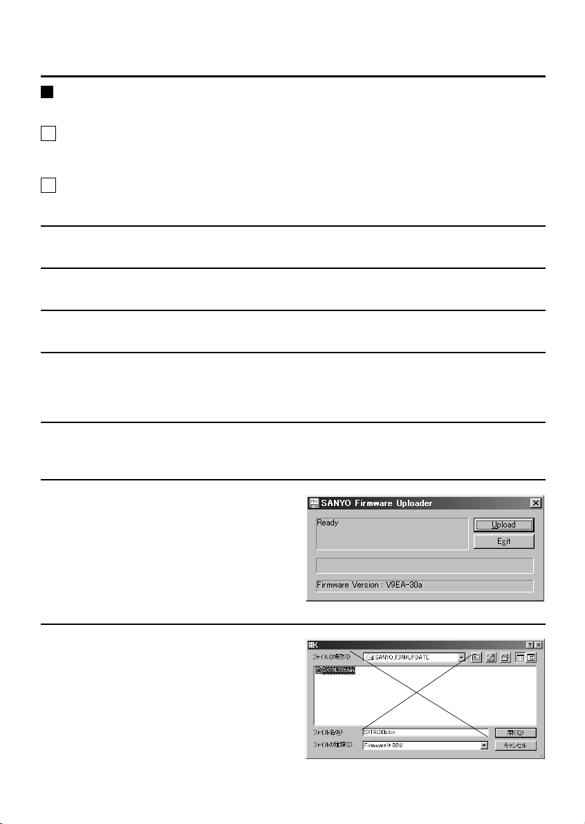
2 Firmware Upload
Use the included CD-ROM to replace the firmware (permanent software) in the camera.
Insert the CD-ROM into the computer’s CD-ROM drive.
1
Turn on the camera, then connect the USB cable between the computer and the camera.
2
From the Windows Start menu, choose Run.
3
Type in “D:Uploader.exe”.
4
(“D” indicates the computer’s CD-ROM drive. If the drive is different, please enter the correct drive
letter.)
Click the OK button.
5
SANYO Firmware Uploader
The “
” window will appear.
Click the Upload button.
6
Open
The “
Make sure the overwriting software file
7
SX19X76r.bin is selected, then press the
Open button.
The “
” window will appear.
Upload
” window will appear.
English
2
Page 4
LAN KIT SETUP
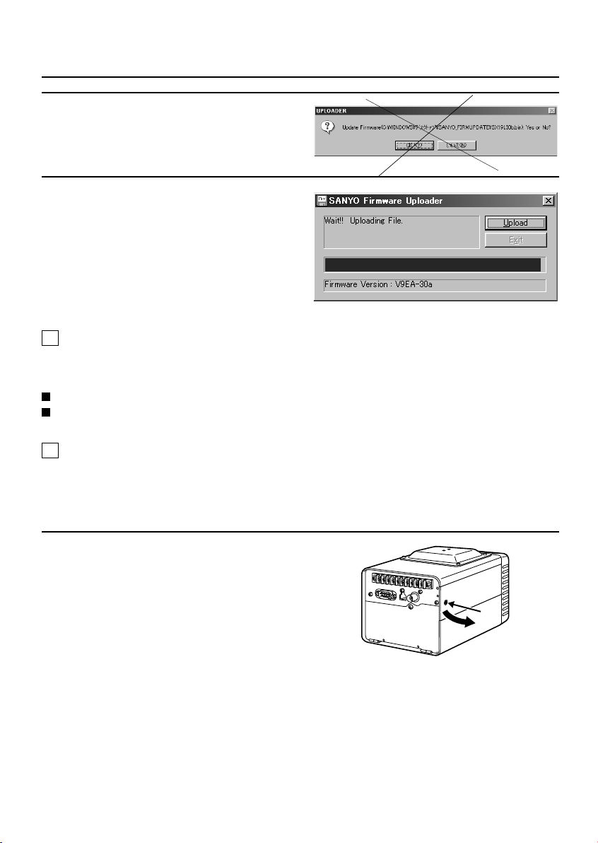
Click the Yes button.
8
Overwriting of the firmware will start.
After the firmware overwriting action has
9
been completed, turn off the camera’s
power.
3 PC Control Setup
The four setting adjustments listed below must be made directly on the camera with the camera’s menu
before the camera can be used on a network. These setting adjustments must be made before installing the
LAN adapter. For details, see “
SET THE RECORDING SPEED (RECORDING SPEED SET)
CHOOSE THE NETWORK SETTINGS (NETWORK SET)
4 LAN Kit Installation
The following explains how to install the LAN kit and connect the network.
Use an Ethernet cable for the network cable.
PC CONTROL SETUP (PC CONTROL SET)
”. (☞ P. 8)
Note:
Make sure the camera power is Off before installing the LAN kit.
Use a screwdriver to remove the set screw
1
, then slide the operation panel cover to
A
the left and remove it.
The removed cover is not used when the LAN
kit is in place.
3
English
A
Page 5
LAN KIT SETUP
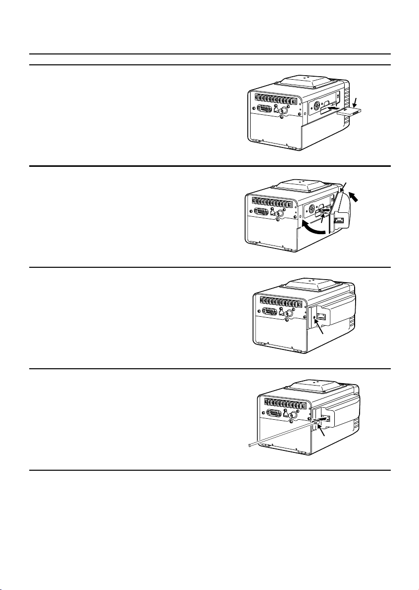
Insert the LAN card B into the camera’s
2
expansion slot.
Insert the LAN card so that the direction
arrow is on the top side and pointing in.
Slip the 2 retaining tabs C on the right
3
side of the LAN kit into place on the
camera body, then insert the adapter’s
cable D into the opening in the LAN card
while pulling the adapter down into place
against the side of the camera.
Secure the LAN kit into place with the set
4
screw E.
B
C
1
D
2
Connect the network cable F to the LAN
5
kit.
Connect the other end of the network
6
cable to your Ethernet hub.
E
F
English
4
Page 6

MENU SETUP AFTER FIRMWARE
UPDATE
Flow of Setup Windows
The following menu window structure will be established by the firmware update.
b Hard Disk Capacity Settings
MAIN MENU Screen
(MAIN MENU)
RECORD START
PLAYBACK
SETTINGS
CONDITION
(HDD SET)
<SUSPICION SHOTS: 10215PCS>
<ALARM TIME 0 H 45MIN>
<PRE ALARM 0 H 15MIN>
<POST ALARM 0 H 30MIN>
SPACE SET
INITIALIZE
[MENU] (SETTINGS)
(SPACE SET)
<SUSPICION SHOTS: 10215PCS>
<ALARM TIME 0 H 15MIN>
PRE ALARM 0 H 30 MIN
POST ALARM 0 H 45 MIN
SETUP YES
(SPACE SET)
<SUSPICION SHOTS: 10215PCS>
<ALARM TIME 0 H 15MIN>
PRE ALARM 0 H 30 MIN
POST ALARM 0 H 45 MIN
SETUP YES
DO NOT POWER OFF!
SETTING NOW!
MENU SET
SETTINGS Screen
(SETTINGS)
CLOCK SET
SYSTEM SET
HDD SET
SUMMER TIME/DAYLIGHT SET
KEY WORD SET
PC CONTROL SET
[MENU] (MAIN MENU)
Menus Requiring Action after Firmware
●
SET
(INITIALIZE)
PASSWORD:
ABCDEFGHIJKLM
NOPQRSTUVWXYZ
0123456789
BS END
b PC Control Setup
(PC CONTROL SET)
RECORDING SPEED SET
NETWORK SET
[MENU] (SETTINGS)
(NETWORK SET)
IP ADDRESS : 192.168. 0. 10
SUBNET MASK: 255.255.255. 0
GATEWAY : 192.168. 0. 1
USER ID : ADMIN
PASSWORD :
(CHANGE PASSWORD-NETWORK)
OLD PASSWORD:
NEW PASSWORD:
VERIFICATION:
ABCDEFGHIJKLM
NOPQRSTUVWXYZ
0123456789
BS END
Update
Hard Disk Capacity Settings (HDD SET) (☞ P. 6)
PC Control Setup (PC CONTROL SET) (☞ P. 8)
(HDD INITIALIZE)
<SUSPICION SHOTS: 10215PCS>
<ALARM TIME 0 H 15MIN>
PRE ALARM 0 H 30 MIN
POST ALARM 0 H 45 MIN
INITIALIZE YES
(RECORDING SPEED SET)
PRE ALARM RATE --- 3 FPS
CAMERA RECORDING FRAMERATE
UNDER PC CONTROL
(IP ADDRESS SET)
IP ADDRESS : 192.168. 0. 10
0123456789
END
(USER ID SET)
USER ID :ADMIN
ABCDEFGHIJKLM
NOPQRSTUVWXYZ
0123456789
BS END
Menus Requiring No Action after Firmware
●
(HDD INITIALIZE)
<SUSPICION SHOTS: 10215PCS>
<ALARM TIME 0 H 15MIN>
PRE ALARM 0 H 30 MIN
POST ALARM 0 H 45 MIN
DO NOT POWER OFF!
INITIALIZING NOW!
(SUBNET MASK SET)
SUBNET MASK: 255.255.255. 0
0123456789
END
(GATEWAY SET)
GATEWAY : 192.168. 0. 1
0123456789
END
Update
Please consult the digital recording camera’s
instruction manual for steps on setting the
following 4 items.
SETTING THE CLOCK (CLOCK SET)
SYSTEM SETTINGS (SYSTEM SET)
SUMMER TIME SETTINGS (SUMMER
TIME/DAYLIGHT SET)
KEY WORD SETTING (KEYWORD SET)
5
English
Page 7

HARD DISK CAPACITY SETTINGS (HDD SET)
The first screen for Hard Disk initialization Setting will look like Fig. 1. The following explains how to change
the hard disk capacity or initialize (reformat) the disk.
About FAT 32
The firmware of the LAN connection kit is based on
FAT 32 disk storage architecture. The FAT file
system used by the previous firmware could handle
hard disks with capacity up to 10GB, but FAT 32 file
system can be used on disks up to 137GB. To use
FAT 32, however, the hard disk must be initialized
after the firmware update.
Initializing the Hard Disk
Initializing the hard disk will erase all data for
previously stored images. Be sure to transfer the
stored image data to your computer before
initializing the camera’s hard disk.
As a safeguard for stored image data, a password
is required for initializing the hard disk. For more
information about passwords, see the digital
recording camera’s instruction manual.
Use the CURSOR (j or l) button to
1
select “SETTINGS”, then press the SET
button.
The SETTINGS screen will appear.
Use the CURSOR (j or l) button to
2
select “HDD SET”, then press the SET
button.
The HDD SET screen will appear.
Use the CURSOR (j or l) button to
3
select “INITIALIZE”, then press the SET
button.
The INITIALIZE screen will appear, allowing
entry of the password.
(HDD SET)
<SUSPICION SHOTS: 10215PCS>
<ALARM TIME 0 H 45MIN>
<PRE ALARM 0 H 15MIN>
<POST ALARM 0 H 30MIN>
SPACE SET
INITIALIZE
[MENU] (SETTINGS)
(Fig. 1)
Use the CURSOR button and the SET
4
button to enter the password from the
alphanumeric pallet.
The PASSWORD field will display asterisks for
entered letters and numbers.
(INITIALIZE)
PASSWORD :
Alphanumeric
Pallet
Use the CURSOR (j or l) button to
5
select “END”, then press the SET button.
????????????????
Use the CURSOR (j or l) button to
6
select “YES”, then press the SET button.
?????????????????
Use the CURSOR button to the set the
7
capacity in the alarm area.
Example:
Set PRE ALARM for 30 minutes.
1
Set POST ALARM for 45 minutes.
2
Values for “
ALARM TIME
“
ABCDEFGHIJKLM
NOPQRSTUVWXYZ
0123456789
BS END
(INITIALIZE)
DO YOU FORMAT THE DISK?
YES
NO
SUSPICION SHOTS
” will be set automatically.
” and
English
6
Page 8

HARD DISK CAPACITY SETTINGS (HDD SET)
Use the CURSOR (j or l) button to
8
select “INITIALIZE”, use the CURSOR (d or
) button to select “YES”, then press the
c
SET button.
The hard disk will be initialized and the display
will return to the SETTINGS screen.
Selecting “NO” will bring up the HDD SET
screen.
(HDD INITIALIZE)
<SUSPICION SHOTS: 10215PCS>
<ALARM TIME 0 H 15MIN>
PRE ALARM 0 H 30 MIN
POST ALARM 0 H 45 MIN
INITIALIZE YES
(HDD INITIALIZE)
<SUSPICION SHOTS: 10215PCS>
<ALARM TIME 0 H 15MIN>
PRE ALARM 0 H 30 MIN
POST ALARM 0 H 45 MIN
DO NOT POWER OFF!
INITIALIZING NOW!
Changing Alarm Capacity
The SPACE SET screen will appear when the disk
has been initialized or when POST ALARM images
have not been recorded on the PRE ALARM area of
the hard disk.
Alarm capacity can be changed in the SPACE SET
screen. However, if images have already been
recorded on the POST ALARM area of the hard
disk, the alarm capacity cannot be changed. In this
case, if capacity adjustment is desired, delete the
alarm images or initialize the hard disk, then adjust
the alarm capacity.
Use the CURSOR (j or l) button to
1
select “SETTINGS”, then press the SET
button.
The SETTINGS screen will appear.
Use the CURSOR (j or l) button to
2
select “HDD SET”, then press the SET
button.
The HDD SET screen will appear.
Use the CURSOR button to reset the
4
capacity values in the alarm area.
Example:
Set PRE ALARM for 3 hours, 30 minutes.
1
Set POST ALARM for 2 hours, 45 minutes.
2
Values for “
ALARM TIME
“
Note:
If a value is already recorded in the suspicion
SUSPICION SHOTS
” will be set automatically.
area, the alarm capacity set time will be
different.
(HDD SET)
<SUSPICION SHOTS: 10215PCS>
<ALARM TIME 0 H 45MIN>
<PRE ALARM 0 H 15MIN>
<POST ALARM 0 H 30MIN>
SPACE SET
INITIALIZE
[MENU] (SETTINGS)
Use the CURSOR (j or l) button to
5
(SPACE SET)
<SUSPICION SHOTS: 10215PCS>
<ALARM TIME 0 H 45MIN>
PRE ALARM 0 H 15 MIN
POST ALARM 0 H 30 MIN
SETUP NO
select “SET UP”, use the CURSOR (d or c)
button to select “YES”, then press the SET
button.
The alarm capacity will be changed and the
display will return to the SPACE SET screen.
Selecting “NO” will bring up the HDD SET
screen.
(SPACE SET)
<SUSPICION SHOTS: 10215PCS>
<ALARM TIME 4 H 15MIN>
PRE ALARM 0 H 30 MIN
POST ALARM 0 H 45 MIN
SETUP YES
(SPACE SET)
<SUSPICION SHOTS: 10215PCS>
<ALARM TIME 1 H 15MIN>
PRE ALARM 0 H 30 MIN
POST ALARM 0 H 45 MIN
SETUP YES
DO NOT POWER OFF!
SETTING NOW!
” and
Use the CURSOR (j or l) button to
3
select “SPACE SET”, then press the SET
button.
The SPACE SET screen will appear.
7
English
Page 9

PC CONTROL SETUP (PC CONTROL SET)
The setup steps explained below are necessary for connection of the digital recording camera to a network or
for control of the camera from a computer directly connected with USB.
Set the recording speed
1
Choose the network settings
2
Set the recording speed
Set the recording frame rate that will be used when
the camera is connected to a network or USB. By
lowering the frame rate from the regular setting,
the camera is able to record even when connected
to the computer.
The following frame rates can be set for this
purpose.
Pre Alarm recording rate (PRE ALARM RATE)
●
Use the CURSOR (j or l) button to
1
select “SETTINGS”, then press the SET
button.
The SETTINGS screen will appear.
Use the CURSOR (j or l) button to
2
select “PC CONTROL SET”, then press the
SET button.
The PC CONTROL SET screen will appear.
Use the CURSOR (j or l) button to
3
select “RECORDING SPEED SET”, then
press the SET button.
The RECORDING SPEED SET screen will appear.
SET
(PC CONTROL SET)
RECORDING SPEED SET
NETWORK SET
PC CONTROL ----------- ON
RECORD STOP FROM PC -- OFF
[MENU] (SETTINGS)
???Use the CURSOR (j or l) button to
4
select “PRE ALARM RATE”, then use the
CURSOR (d or c) button to select “1”.
3FPS:
Records 3 image every second.
1FPS:
Records 1 image every second.
(RECORDING SPEED SET)
PRE ALARM RATE --- 3 FPS
CAMERA RECORDING FRAMERATE
UNDER PC CONTROL
After completion of the settings, press the
5
MENU button.
The PC CONTROL SET screen will reappear.
Keep pressing the MENU button until the
MAIN MENU screen appears.
(RECORDING SPEED SET)
PRE ALARM RATE --- 1 FPS
CAMERA RECORDING FRAMERATE
UNDER PC CONTROL
(RECORDING SPEED SET)
PRE ALARM RATE --- 3 FPS
CAMERA RECORDING FRAMERATE
UNDER PC CONTROL
English
8
Page 10

PC CONTROL SETUP (PC CONTROL SET)
Choose the network settings
The following settings are necessary to use the
camera on a network.
Note:
● Contact your network administrator to obtain
the appropriate IP address.
● ???????????????? ???????????????
??????????????? ???????????????
A Set the IP Address, Subnet Mask
and Gateway
Example: The initial IP address 192.168.000.010
1
2
3
will be changed to 130.141.110.204.
Use the CURSOR (j or l) button to
select “SETTINGS”, then press the SET
button.
The SETTINGS screen will appear.
Use the CURSOR (j or l) button to
select “PC CONTROL SET”, then press the
SET button.
The PC CONTROL SET screen will appear.
Use the CURSOR (j or l) button to
select “NETWORK SET”, then press the SET
button.
The NETWORK SET screen will appear.
SET
(PC CONTROL SET)
RECORDING SPEED SET
NETWORK SET
Use the CURSOR (j or l) button to
4
select “IP ADDRESS SET”, then press the
SET button.
The IP ADDRESS SET screen will appear.
(NETWORK SET)
IP ADDRESS : 192.168. 0.10
SUBNET MASK: 255.255.255. 0
GATEWAY : 192.168. 0. 1
USER ID : ADMIN
PASSWORD : ********
Use the CURSOR button to select “1” from
5
the numeric pallet, then press the SET
button.
Use the same technique to select the
remaining numbers “
30.141.110.204.
12 digits are selected, the cursor will
automatically move to “
(IP ADDRESS SET)
IP ADDRESS : 192.168. 0. 10
0123456789
END
SET
END
”.
(IP ADDRESS SET)
IP ADDRESS : 130.141.110. 10
0123456789
END
(IP ADDRESS SET)
IP ADDRESS : 130.141.110.204
” After
9
English
[MENU] (SETTINGS)
(NETWORK SET)
IP ADDRESS : 192.168. 0. 10
SUBNET MASK: 255.255.255. 0
GATEWAY : 192.168. 0. 1
USER ID : ADMIN
PASSWORD : ********
0123456789
END
Press the SET button.
6
The display will return to the NETWORK SET
screen.
Page 11

Use the same method to set the SUBNET
7
MASK and GATEWAY numbers.
(NETWORK SET)
IP ADDRESS : 130.141.110.204
SUBNET MASK: 255.255.255. 0
GATEWAY : 192.168. 0. 1
USER ID : ADMIN
PASSWORD : ********
After completion of the settings, press the
8
MENU button.
The PC CONTROL SET screen will reappear.
Keep pressing the MENU button until the
MAIN MENU screen appears.
B Set the User ID (up to 5 characters)
Example: The initial user ID “ADMIN” will be
1
2
changed to “USER1”.
Use the CURSOR (j or l) button to
select “SETTINGS”, then press the SET
button.
The SETTINGS screen will appear.
Use the CURSOR (j or l) button to
select “PC CONTROL SET”, then press the
SET button.
The PC CONTROL SET screen will appear.
Use the CURSOR (j or l) button to
3
select “NETWORK SET”, then press the
SET button.
The NETWORK SET screen will appear.
SET
Use the CURSOR (j or l) button to
4
(PC CONTROL SET)
RECORDING SPEED SET
NETWORK SET
[MENU] (SETTINGS)
(NETWORK SET)
IP ADDRESS : 192.168. 0. 10
SUBNET MASK: 255.255.255. 0
GATEWAY : 192.168. 0. 1
USER ID : ADMIN
PASSWORD : ********
select “USER ID”, then press the SET
button.
The USER ID SET screen will appear, allowing
entry of the password.
(NETWORK SET)
IP ADDRESS : 192.168. 0.10
SUBNET MASK: 255.255.255. 0
GATEWAY : 192.168. 0. 1
USER ID : ADMIN
PASSWORD : ********
English
10
Page 12

PC CONTROL SETUP (PC CONTROL SET)
Use the CURSOR button to select “U” from
5
the alphanumeric pallet, then press the
SET button.
Use the same technique to select the
remaining letters “
SER1
”. After 5 letters are
selected, the cursor will automatically move to
END
“
”.
(USER ID SET)
USER ID :UDMIN
ABCDEFGHIJKLM
NOPQRSTUVWXYZ
0123456789
BS END
(USER ID SET)
USER ID :USER1
ABCDEFGHIJKLM
NOPQRSTUVWXYZ
0123456789
BS END
Press the SET button.
6
SET
The display will return to the NETWORK SET
screen.
After completion of the settings, press the
7
MENU button.
The PC CONTROL SET screen will reappear.
Keep pressing the MENU button until the
MAIN MENU screen appears.
Use the CURSOR (j or l) button to
3
select “NETWORK SET”, then press the SET
button.
The NETWORK SET screen will appear.
SET
Use the CURSOR (j or l) button to
4
(PC CONTROL SET)
RECORDING SPEED SET
NETWORK SET
[MENU] (SETTINGS)
(NETWORK SET)
IP ADDRESS : 192.168. 0. 10
SUBNET MASK: 255.255.255. 0
GATEWAY : 192.168. 0. 1
USER ID : ADMIN
PASSWORD : ********
select “PASSWORD”, then press the SET
button.
In the CHANGE PASSWORD-NETWORK screen,
OLD PASSWORD
the “
SET
” field will be selected.
(NETWORK SET)
IP ADDRESS : 192.168. 0.10
SUBNET MASK: 255.255.255. 0
GATEWAY : 192.168. 0. 1
USER ID : ADMIN
PASSWORD : ********
C Set the Password
(up to 8 characters)
Example: The password will be set to
1
2
11
“CAMERA”.
Use the CURSOR (j or l) button to
select “SETTINGS”, then press the SET
button.
The SETTINGS screen will appear.
?????????????????
????????????????????????
Use the CURSOR (j or l) button to
select “PC CONTROL SET”, then press the
SET button.
The PC CONTROL SET screen will appear.
English
(CHANGE PASSWORD-NETWORK)
OLD PASSWORD:
NEW PASSWORD:
VERIFICATION:
ABCDEFGHIJKLM
NOPQRSTUVWXYZ
0123456789
BS END
Page 13

Use the CURSOR button to select “END”,
5
then press the SET button.
The selected field will move from “
NEW PASSWORD
“
Note:
????? ????? ????? ????? ????? ?????
”.
????? ????? ????? ????? ????? ?????
????? ????? ????? ????? ?????
(CHANGE PASSWORD-NETWORK)
SET
Use the CURSOR button to select “C”,
6
OLD PASSWORD:
NEW PASSWORD:
VERIFICATION:
ABCDEFGHIJKLM
NOPQRSTUVWXYZ
0123456789
BS END
(CHANGE PASSWORD-NETWORK)
OLD PASSWORD:
NEW PASSWORD:
VERIFICATION:
ABCDEFGHIJKLM
NOPQRSTUVWXYZ
0123456789
BS END
then press the SET button.
An asterisk will be displayed for the entered
character. Use the same technique to select
the remaining letters “
SET
AMERA
”.
(CHANGE PASSWORD-NETWORK)
OLD PASSWORD:
NEW PASSWORD:
VERIFICATION:
ABCDEFGHIJKLM
NOPQRSTUVWXYZ
0123456789
BS END
END
” to
Use the CURSOR button to select “END”,
7
then press the SET button.
The “******” (CAMERA) password will be
set, and the selected field will move to
VERIFICATION
“
”.
Verification checks for proper entry of the
desired password.
(CHANGE PASSWORD-NETWORK)
SET
Use the CURSOR button and the SET
8
OLD PASSWORD:
NEW PASSWORD:
VERIFICATION:
ABCDEFGHIJKLM
NOPQRSTUVWXYZ
0123456789
BS END
button to enter “CAMERA” one more
time, and then select “END” again and
press the SET button.
CAMERA
“
” will be set as the password and
the NETWORK SET screen will reappear.
(CHANGE PASSWORD-NETWORK)
SET
After completion of the settings, press the
9
OLD PASSWORD:
NEW PASSWORD:
VERIFICATION:
ABCDEFGHIJKLM
NOPQRSTUVWXYZ
0123456789
BS END
MENU button.
The PC CONTROL SET screen will reappear.
Keep pressing the MENU button until the
MAIN MENU screen appears.
(CHANGE PASSWORD-NETWORK)
OLD PASSWORD:
NEW PASSWORD:
VERIFICATION:
ABCDEFGHIJKLM
NOPQRSTUVWXYZ
0123456789
BS END
English
12
Page 14

PC CONTROL SETUP (PC CONTROL SET)
Changing Set Entries
The 2 types of entry pallets are shown below.
Numeric Pallet (for addresses)
(IP ADDRESS SET)
IP ADDRESS :130.141.110.204
0123456789
END
Alphanumeric Pallet (for User ID and Password)
(USER ID SET)
USER ID :USER1
ABCDEFGHIJKLM
NOPQRSTUVWXYZ
0123456789
BS END
Example 1: Changing the addresses from
“130141.110.204” to
“131.141.110.204” with the numeric
pallet.
Use the CURSOR button to select the “í”
1
or “ü” field.
(IP ADDRESS SET)
IP ADDRESS :130.141.110.204
0123456789
END
Press the SET button as many times as
2
needed to place the shaded correction
cursor (ú) over the “T”.
(IP ADDRESS SET)
IP ADDRESS :130.141.110.204
0123456789
END
Use the CURSOR button to select “0” from
3
the numeric pallet, then press the SET
button.
(IP ADDRESS SET)
IP ADDRESS :131.141.110.204
13
English
0123456789
END
Use the CURSOR button to select “END”
4
from the numeric pallet, then press the
SET button.
Page 15

Example 2: Changing the USER ID from
“UTER1” to “USER1” with the
alphanumeric pallet.
Use the CURSOR button to select the
1
“íBS” (backspace) field.
(USER ID SET)
USER ID :UTER1
ABCDEFGHIJKLM
NOPQRSTUVWXYZ
0123456789
BS END
Note: ????? ????? ????? ????? ????? ?????
????? ????? ????? ????? ????? ?????
????? ????? ????? ????? ?????
Press the SET button as many times as
2
needed to place the shaded correction
cursor (ú) over the “T”.
(USER ID SET)
USER ID :UTER1
ABCDEFGHIJKLM
NOPQRSTUVWXYZ
0123456789
BS END
Use the CURSOR button to select “S” from
3
the alphanumeric pallet, then press the
SET button.
(USER ID SET)
USER ID :USER1
ABCDEFGHIJKLM
NOPQRSTUVWXYZ
0123456789
BS END
Use the CURSOR button to select “END”
4
from the alphanumeric pallet, then press
the SET button.
To enter a space in your USER ID or
PASSWORD, select the blank spot directly
below the letter “N”, then press the SET
button.
English
14
Page 16

1AC6P1P2505-L9EAA/WA (0901KP-BB)
SANYO Electric Co., Ltd.
Printed in Japan
 Loading...