

Page 1
INSTRUCTION MANUAL
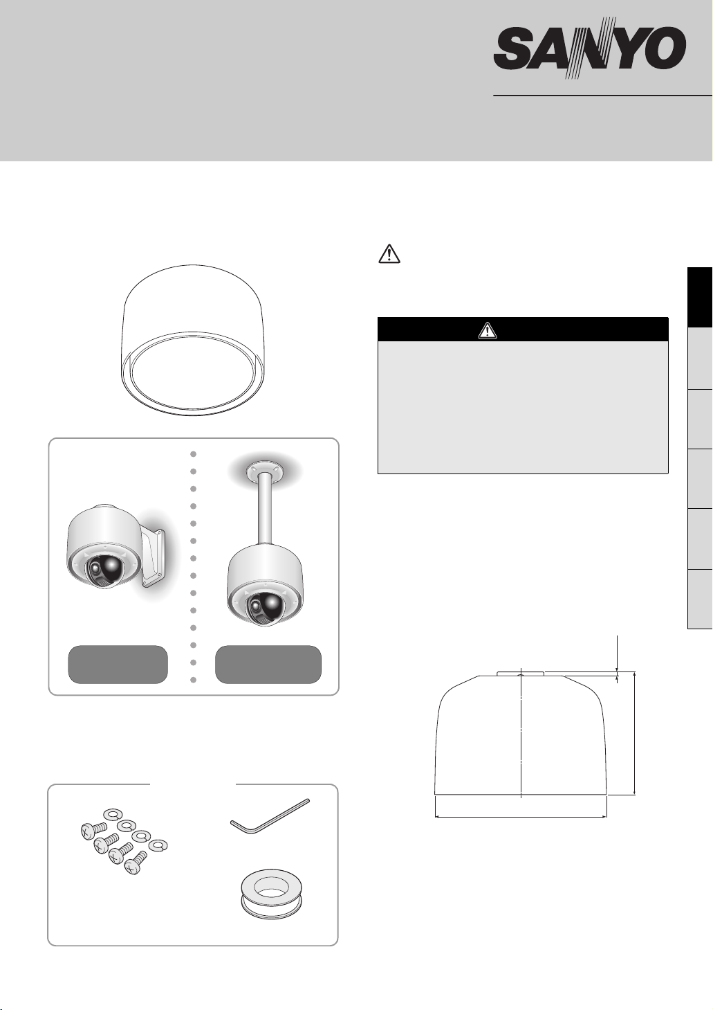
Outdoor Housing
This installation should be made by a qualified service
person and should conform to all local codes.
About this manual
This housing is designed for outdoor installation.
Before installing and using this unit, please read this manual carefully. Be sure to keep it handy for later reference.
CAUTION:
Install this housing securely according to this
installation manual. Be aware that allowing the bracket
to fall with the camera on it may cause personal injury.
• Be careful when opening holes for installing the
unit. Work with the power and video cables pulled
out for easy installation.
• Make sure to properly perform waterproofing for the
ceiling or wall where you are installing the unit.
• Make sure that the surface in the installation
location has no unevenness and is strong enough
to bear the total weight of the unit.
VA-80EX
Important
EnglishFrançaisEspañolDeutsch中文简体日本語
Example of
wall mounting
Example of
pendant mounting
Accessories
Hexagonal wrench
Screws, washers
(for power board unit)
Waterproof tape
Features and specifications are subject to change without
prior notice or obligations.
b Specifications
Color: Beige
Material: Metal
Waterproof Standard: Conforming to IP66
Operating Environment
(with power source connected) :
Temperature; -30°C - +50°C (-22°F - +122°F)
Humidity; less than 90% RH (no condensation)
Weight: Approx. 2.5 kg (5.5 lb)
Dimensions:
6 (0.2)
182 (7.2)
Ǿ248 (9.8)
Unit: mm (inch)
b Specifications of Heater
(built into VA-CM8C/CM8S)
Automatic switch ON/OFF temperature:
ON; Approx. 5°C (41°F)
OFF; Approx. 15°C (59°F)
Power supply: 24 V AC ± 10%, 50/60Hz
Power consumption: Max. 35 W (When heater turned on)
Page 2
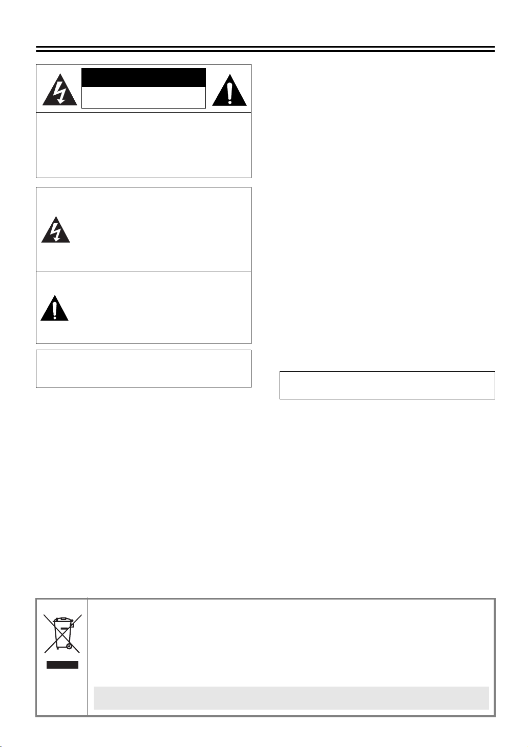
Safety precautions
CAUTION
RISK OF ELECTRIC SHOCK
DO NOT OPEN
CAUTION:
SHOCK, DO NOT REMOVE COVER (OR BACK).
NO USER-SERVICEABLE PARTS INSIDE.
REFER SERVICING TO QUALIFIED SERVICE
PERSONNEL.
TO REDUCE THE RISK OF ELECTRIC
The lightning flash with arrowhead
symbol, within an equilateral triangle, is
intended to alert the user to the presence
of uninsulated “dangerous voltage” within
the product’s enclosure that may be of
sufficient magnitude to constitute a risk of
electric shock to persons.
The exclamation point within an
equilateral triangle is intended to alert the
user to the presence of important
operating and maintenance (servicing)
instructions in the literature
accompanying the product.
CAUTION: Changes or modifications not expressly
approved by the manufacturer may void the user’s authority
to operate this equipment.
This equipment has been tested and found to comply with
the limits for a Class B digital device, pursuant to Part 15 of
the FCC Rules.
These limits are designed to provide reasonable protection
against harmful interference in a residential installation.
This equipment generates, uses and can radiate radio
frequency energy and, if not installed and used in
accordance with the instructions, may cause harmful
interference to radio communications. However, there is no
guarantee that interference will not occur in a particular
installation.
If this equipment does cause harmful interference to radio
or television reception, which can be determined by turning
the equipment off and on, the user is encouraged to try to
correct the interference by one or more of the following
measures.
• Reorient or relocate the receiving antenna.
• Increase the separation between the equipment and
receiver.
• Connect the equipment into an outlet on a circuit
different from that to which the receiver is connected.
• Consult the dealer or an experienced radio/TV
technician for help.
WARNING: To reduce a risk of fire or electric
shock, do not expose this product to rain or
moisture.
CAUTION:
• Do not touch the connection cables and the power
supply plug with wet hands.
• Do not insert any metal, inflammable, or foreign object
into the cable hole. Doing so may cause fire or electric
shock.
• Since this product does not have waterproof
construction, do not expose it to water or other liquids.
Also, do not install it in a bathroom or shower room.
Doing so may cause fire or electric shock.
• Do not install the product on unsteady surfaces as it may
fall and cause injury or damage.
• Do not expose the product to shocks or install it in places
subject to vibration.
b WEEE Symbol Information
Please note:
Your SANYO product is designed and manufactured with high quality materials and components which can be
recycled and reused.
This symbol means that electrical and electronic equipment, at their end-of-life, should be disposed of
separately from your household waste.
Please dispose of this equipment at your local community waste collection/recycling centre.
In the European Union there are separate collection systems for used electrical and electronic products.
Please help us to conserve the environment we live in!
This symbol mark and recycle system are applied only to EU countries and not applied to the
countries in the other area of the world.
For the customers in Canada
This class B digital apparatus complies with
Canadian ICES-003.
1
Page 3

Assembling the Outdoor Housing
● For the built-in heater and fan in the dome cover, you need an additional 24 V AC power supply.
● This housing is used in combination with a dome cover (clear/smoked) and a mounting bracket (wall/
pendant) that are sold separately.
☞ For how to install an assembled housing, refer to the instruction manual for the bracket used.
Also refer to the instruction manual for each associated device.
1. Attaching the dome cover
Hook the safety wire (A) of the dome cover on hook
1
hole (A’) located inside the housing.
Connect the heater cable (B) to the heater terminal
2
(B’) and the fan cable (C) to the fan terminal (C’).
C
A
B
B’
A’
Dome Cover:
• VA-CM8C (Clear)
• VA-CM8S (Smoked)
C’
2. Mounting the power board unit
Pass the supplied screws through power board
1
unit screw holes (D) and fasten them loosely using
washers (4 places).
Mount the power board unit in the housing aligning
2
the arrows (E) of the same color (blue) on them,
and then firmly tighten the screws loosely
fastened in the previous step.
• Make sure the terminal (F) and its cable are located
along the inner lateral face of the housing.
• Pull the video cable led from the ceiling or wall
toward the power board unit.
Power Board Unit:
VA-84S/80S
Video cable
D
3. Connecting cables
Connect the 24 V AC power cable to the terminal (F).
1
F
Connect other cables to the power board unit.
2
☞ For details, please refer to “Connections and Settings”
in the Installation Manual that comes with the camera
unit.
4. Mounting the camera unit
Fasten the camera unit safety wire (G) to the hook
1
(G’) inside the power board unit.
Align the arrows (E) of the same color (blue) on the
2
camera unit and the housing inner face, and push
the camera until you hear a click.
Remove the plastic cover (H) of the camera unit.
3
Attach the dome cover by fastening 4 screws (J)
4
using the supplied hexagonal wrench.
G’
G
D
E; Blue
Fix the housing onto the mounting bracket (wall/
3
pendant).
☞ For details, please refer to “Outdoor Type” in the
Mounting Bracket Instruction Manual.
D
D
a
b
F
*
* To remove the camera unit
2
E; Blue
*
H
J
J
J
J
 Loading...