

Page 1
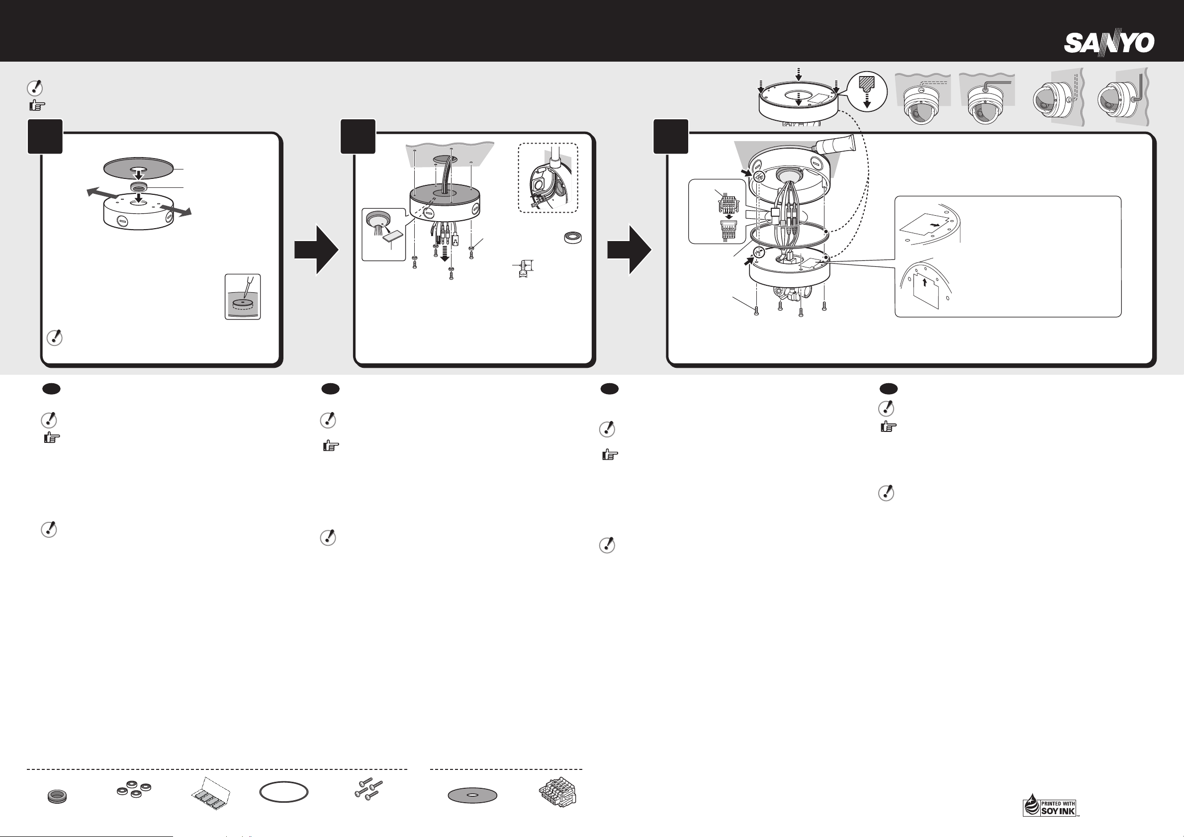
Base Bracket
❷
❶
Rubber-faced washer
Putty
G3/4
F
4.0 (0.16)
40 (1.6) or more
F
10 (0.4) or less
Unit: mm (inch)
❶ Make sure to tighten the commercially available screws
properly. Using screws of sizes other than specified may
cause the unit to fall.
❷ Fill the gap between the rubber cap and the cable by
applying the supplied putty from inside the base bracket.
Apply a sufficient amount of putty to ensure
waterproofness.
•
❶ Fit the waterproof ring tightly in the groove. If the ring is not tightly fit in the groove, water may come into the unit.
❷ Do not hang the camera unit by holding the camera cable.
❹ Make sure to tighten the screws properly.
Confirm the orientation of the rubber cap as the shape differs
between the upper and lower sides of the cap. Be sure to
securely fit the rubber cap in the bracket.
If you pull out the cable from the ceiling or wall,
make a small hole in the center of the rubber
cap.
•
(VA-85BX: Sold separately)
By using the base bracket, you can house the connection cable inside the bracket or take out the cable from the side face of it to wire the cable in the desired direction.
Be sure to install the base bracket by strictly following the steps below to ensure waterproofness.
Refer to the Installation Manual of the camera for the proper removal and installation of the dome cover, wiring, adjustment of angle of view and the like.
1 2 3
Cushioning Sheet
(A)
Ceiling Mounting: Direct the arrow (A) or (B) to the
subject.
Wall Mounting: Direct the arrow (A) or (B) upward.
Rubber Cap
(B)
Connector
Waterproof
❶
Ring
Screws for
❹
camera
mounting
Push
❷
❺If the installation location needs waterproof treatment, take
appropriate measures such as caulking between the base
bracket and the ceiling (wall).
Waterproofness (IP66) is not guaranteed if such a treatment is
made improperly.
❸
WAL L TOP
CEILING
CEILING
WAL L TOP
Ceiling Mounting:
Direct the arrow (⬆CEILING) to the subject.
Wall Mounting:
Direct the arrow (⬆WALL TOP) upward.
En utilisant le support de base, vous pouvez loger le câble de
F
connexion à l’intérieur du support ou sortir le câble par le côté
pour le faire cheminer dans la direction souhaitée.
Assurez-vous d’installer le support de base en suivant scrupuleusement
les étapes ci-dessous pour garantir l’étanchéité à l’eau.
Reportez-vous au manuel d’installation de la caméra pour savoir
comment retirer et installer correctement le couvercle du dôme, les
câbles, régler l’angle de vue, et autres opérations similaires.
Vérifiez l’orientation du bouchon en caoutchouc car la forme peut être
différente entre le côté supérieur et le côté inférieur du bouchon. Assurezvous de la mise en place solide du bouchon en caoutchouc dans le support.
Si vous amenez le câble par le plafond ou le mur, pratiquez un petit trou
•
au centre du bouchon en caoutchouc.
Montage au plafond: diriger la flèche (A) ou (B) vers le sujet.
Montage mural: diriger la flèche (A) ou (B)vers le haut.
❶ Assurez-vous que les vis (disponibles dans le commerce) sont
correctement serrées. Si vous utilisez des vis d’une taille différente de
celle qui est prescrite, l’appareil peut tomber.
❷ Comblez l’espace entre le bouchon en caoutchouc et le câble à l’aide
du mastic fourni à cet effet, en partant de l’intérieur du support de
base.
Appliquez une quantité suffisante de mastic pour assurer l’étanchéité
•
à l’eau.
❶ Ajustez bien le joint étanche dans la rainure. Si le joint étanche n’est
pas bien ajustée à l’intérieur de la rainure, l’eau risque de pénétrer
dans l’appareil.
❷ Ne pas pendre la caméra en la tenant par le câble.
❸ Montage au plafond: diriger la flèche (⬆CEILING) vers le sujet.
Montage mural: diriger la flèche (⬆WALL TOP)vers le haut.
❹ Assurez-vous que les vis sont correctement serrées.
❺ Si l’emplacement d’installation nécessite un traitement
d’imperméabilisation, prenez les mesures appropriées comme un
calfatage entre le support de base et le plafond (mur).
L’étanchéité (IP66) ne peut être garantie si ce traitement est mal
effectué.
Accessories
Rubber Cap
Rubber-faced
(one side) washer
Putty
Waterproof Ring
Mediante el soporte de base, es posible alojar el cable de
E
conexión dentro del soporte o sacar el cable por la parte lateral
del mismo para extender el cable en la dirección deseada.
Asegurarse de instalar el soporte de base ateniéndose
estrictamente a los pasos descritos a continuación para asegurar la
impermeabilidad.
Consultar el Manual de Instalación de la cámara para realizar
adecuadamente el desmontaje y montaje de la tapa de cúpula, el
cableado, el ajuste del ángulo de visual etc.
Comprobar la orientación del tapón de goma porque los lados superior
e inferior del mismo tienen formas diferentes. Asegurarse de instalar
firmemente el tapón de goma en el soporte.
•
Si se hace salir el cable del techo o de la pared, realizar un pequeño
orificio en el tapón de goma.
Montaje en el techo: Dirigir la flecha (A) o (B) hacia el sujeto.
Montaje en la pared: Dirigir la flecha (A) o (B) hacia arriba.
❶ Asegurarse de apretar correctamente los tornillos disponibles en el
mercado. La unidad puede caerse si se usan tornillos que no son los
especificados.
❷ Llenar el espacio entre el tapón de goma y el cable aplicando la
masilla suministrada dentro del soporte de base.
Aplicar una cantidad suficiente de masilla para asegurar la
•
impermeabilidad.
❶ Instalar el anillo de impermeabilidad en la ranura. Si el anillo no se
ajusta bien en la ranura, podría entrar agua en la unidad.
❷ No colgar la unidad de la cámara sujetando el cable de la cámara.
❸ Montaje en el techo: Dirigir la flecha (⬆CEILING) hacia el sujeto.
Montaje en la pared: Dirigir la flecha (⬆WALL TOP)hacia arriba.
❹ Asegurarse de apretar los tornillos correctamente.
❺ Si el lugar de instalación necesita un tratamiento impermeable, realizar
lo necesario como enmasillar el soporte de base y el techo (pared).
No se garantiza la impermeabilidad (IP66) si este tratamiento se
realiza incorrectamente.
Screws for
camera mounting
Camera Accessory
Cushioning Sheet
Connector
Bei Verwendung der Grundplattenhalterung können Sie das
D
Anschlusskabel in der Halterung unterbringen oder das Kabel
seitlich aus der Halterung in die gewünschte Richtung führen
und anschließen.
Gehen Sie bei der Montage der Grundplattenhalterung wie
nachstehend beschrieben vor, um die Wasserdichtigkeit zu
garantieren.
In der Installationsanleitung der Kamera sind der korrekte Ein- und
Ausbau der Kuppelabdeckung, die Verkabelung, die Einstellung des
Aufnahmewinkels etc. beschrieben.
Achten Sie auf die korrekte Richtung des Gummideckels, da die Form
der Ober- und Unterseite des Deckels unterschiedlich ist. Setzen Sie den
Gummideckel fest in die Halterung ein.
Wenn Sie das Kabel von der Decke oder Wand zuführen, erstellen Sie
•
ein kleines Loch in der Mitte des Gummideckels.
Deckenmontage: Richten Sie den Pfeil (A) oder (B) auf das Objekt.
Wandmontage: Richten Sie den Pfeil (A) oder (B) nach oben.
❶
Stellen Sie sicher, dass die handelsüblichen Schrauben fest angezogen
sind. Die Kameraeinheit kann herunterfallen, wenn die Größe der
Befestigungsschrauben nicht den Spezifikationen entspricht.
❷ Füllen Sie den Spalt zwischen dem Gummideckel und dem Kabel,
indem Sie die mitgelieferte Spachtelmasse von der Innenseite der
Grundplattenhalterung auftragen.
Tragen Sie eine ausreichende Menge Spachtelmasse auf, um die
•
Wasserdichtigkeit zu garantieren.
❶ Setzen Sie den wasserdichten Ring fest in die Nut ein. Sitzt der Ring
nicht fest in der Nut, könnte Wasser in die Einheit eindringen.
❷ Hängen Sie die Kameraeinheit nicht am Kamerakabel auf.
❸ Deckenmontage: Richten Sie den Pfeil (⬆CEILING) auf das Objekt.
Wandmontage: Richten Sie den Pfeil (⬆WALL TOP)nach oben.
❹ Stellen Sie sicher, dass die Schrauben fest angezogen sind.
❺ Wenn der Installationsort wasserabweisend gestaltet sein muss,
sehen Sie geeignete Maßnahmen vor, beispielsweise eine Abdichtung
zwischen der Grundplattenhalterung und der Decke (Wand).
Die Wasserdichtigkeit (IP66) kann nicht garantiert werden, wenn keine
geeigneten Maßnahmen vorgesehen wurden.
通过使用底座托架,可将连接电缆放置在托架内,或从其侧面拉出
Ё
电缆,以便按照所需的方向布线。
䇋ࡵᖙϹḐᣝ✻ҹϟℹ偸ᅝ㺙ᑩᑻᠬᶊˈҹֱ䆕䰆∈ᗻDŽ
℆њ㾷བԩℷ⹂䖯㸠⧗㔽ⱘᢚϢᅝ㺙ǃᏗ㒓ǃ㾚㾦䇗㡖ㄝ᪡ˈ䇋
খ䯙ᨘڣ༈ᅝ㺙ݠDŽ
ᔧ‵ⲂᐑϞϟ䴶ᔶ⢊ϡৠᯊˈ䇋⹂䅸‵ⲂᐑⱘᳱDŽ䇋ࡵᖙᇚ‵Ⲃᐑ㋻
ഄᅝ㺙ࠄᠬᶊݙDŽ
བᵰҢ㢅ᵓຕᢝߎ⬉㓚ˈ䇋‵ⲂᐑЁ༂ᣪߎϔϾᇣᄨDŽ
•
天花板安装:Փㆁ༈ᣛ (A) (B) Ⳃ⠽ԧDŽ
墙壁安装:Փㆁ༈ᣛ (A) (B) ϞᮍDŽ
❶ ⹂ֱᏆᅠܼᢻ㋻Ꮦ䴶ߎଂⱘ㶎䩝DŽབՓ⫼⡍ᅮᇣⱘ㶎䩝ˈᕜ᳝ৃ㛑
Փᴀᴎᥝ㨑DŽ
❷ Ңᑩᑻᬃᶊݙ䚼⍖Ϟ㸹ೳˈᇚ‵㛊ᐑϢ㓚㒓П䯈ⱘぎ䱭฿⒵DŽ
䇋Փ⫼䎇䞣ⱘ⊍♄ˈҹֱ䆕䰆∈ᗻDŽ•
❶ ᇚ䰆∈㋻㋻ഄ㺙ߍῑݙDŽབᵰ䰆∈≵᳝㋻㋻ഄ㺙ߍῑݙˈ∈ӑ
ৃ㛑⌕ܹᴀᴎݙDŽ
❷ 䇋࣓Փ⫼ᨘڣ༈⬉㓚 ᣖᨘڣ༈㺙㕂DŽ
❸ 天花板安装:Փㆁ༈ᣛ (⬆CEILING) Ⳃ⠽ԧDŽ
墙壁安装:Փㆁ༈ᣛ (⬆WALL TOP) ϞᮍDŽ
❹ ⹂ֱᏆᅠܼᢻ㋻㶎䩝DŽ
❺ བᵰᅝ㺙ԡ㕂䳔㽕ᠻ㸠䰆∈໘⧚ˈ䇋䞛প䗖ᔧⱘᮑˈ՟བᑩᑻᬃᶊ
Ϣ㢅ᵓ˄ຕ˅П䯈฿䱭DŽ
བᵰϡ䗖ᔧഄ䖯㸠䖭⾡໘⧚ˈህϡ㛑ֱ䆕ヺড়䰆∈ޚ(IP66)DŽ
1AC6P1P4026-L5DE2, L5DK2 (L9BHZ/WA) (0909KR-CA)
Printed in China
 Loading...