

Page 1
INSTALLATION MANUAL
Option Board (Network)
About this manual
Please read this manual before installing and using this unit, and always follow the instructions in it for proper use.
VA-50LAN
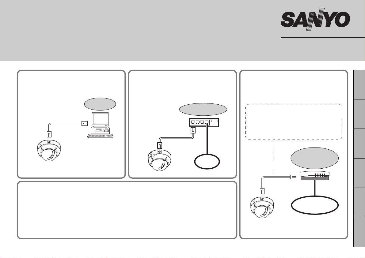
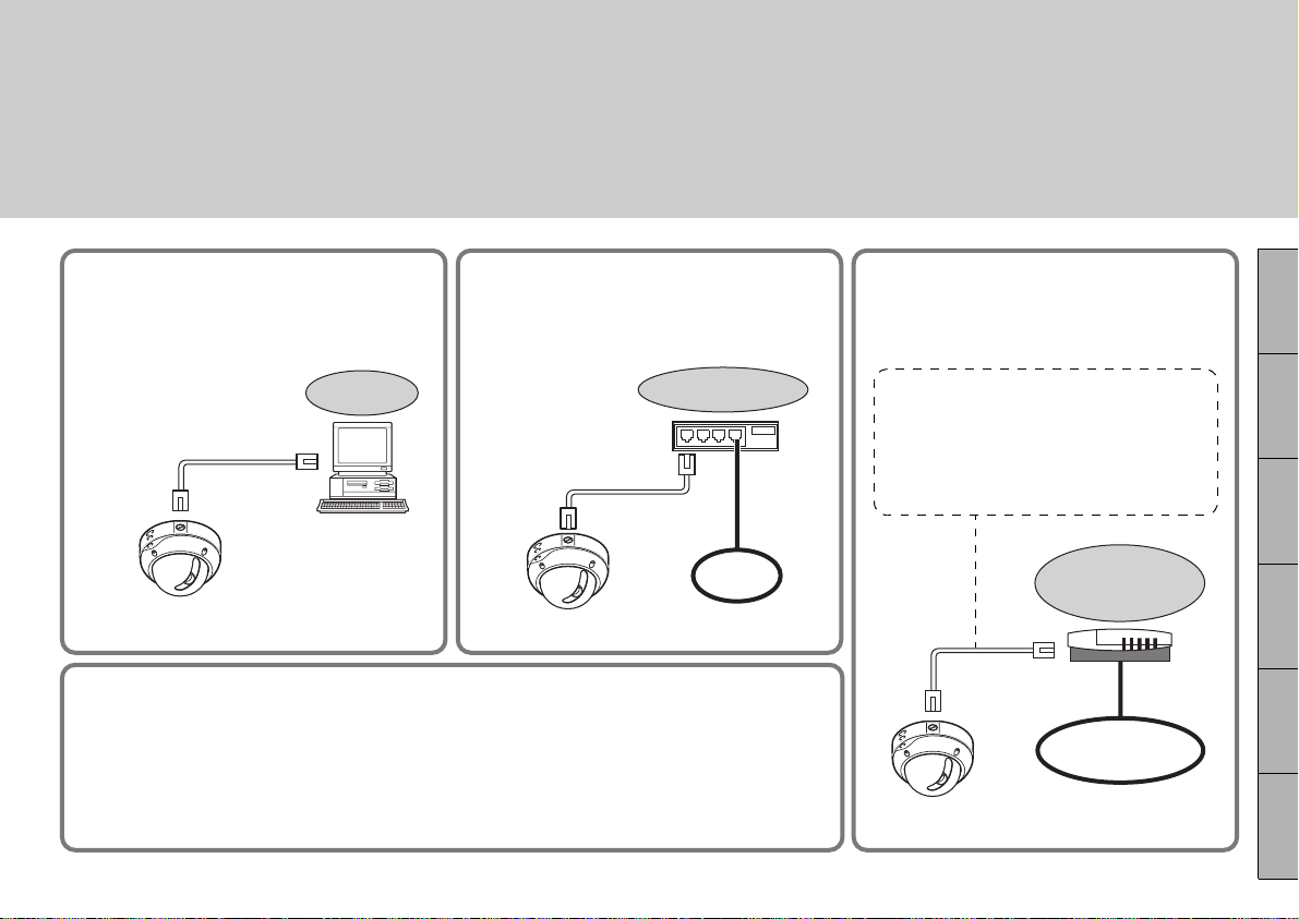
■ Direct connection
Connect the camera to your PC using a LAN
cable (crossover type).
PC
LAN cable
(crossover type)
■ LAN connection
Connect the camera to the LAN through a
switching hub using LAN cables (straight
type).
LAN cable
(straight type)
■ System Requirements
The system requirements for camera operation via network are as follows:
•PC: IBM PC/AT and compatibles
•OS: Windows 2000/Windows XP Home Edition/
Windows XP Professional
•CPU: Pentium III (800MHz or higher)
• Memory: 128MB or more
• Network interface: 10Base-T/100Base-TX
* Use shielded LAN cables.
• Display card: 1024 x 768 pixels or higher,
• Web browser: Internet Explorer Ver.6.0 or higher
16 million colors or higher
Switching hub
LAN
■ Internet connection
Connect the camera to a router or ADSL
modem with LAN interface using LAN
cables.
When connecting to a router, use the
straight type LAN cable.
When connecting to an ADSL modem or
others devices, refer to the instruction
manual for the device.
Router or
ADSL modem
Internet
English Deutsch Français Español
中文简体
日本語
Page 2
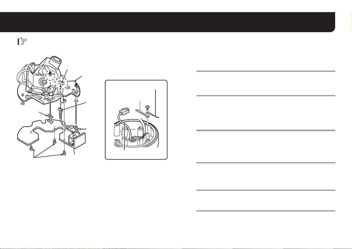
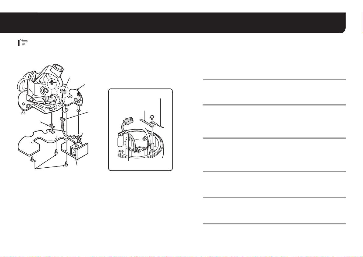
1. Installing the Option Board
Remove the dome cover and then the lens assembly. Place the dome cover back once you have finished the settings.
• Please refer to the Installation Manual supplied with the camera.
Connect the option board pin connector to the
1
COM/NET terminal located at the reverse side of
the lens assembly.
Fit the spacers on the option board into the lens
2
assembly (2 places).
Fix the option board from the reverse side using
3
the screws supplied with the option board
(3 places).
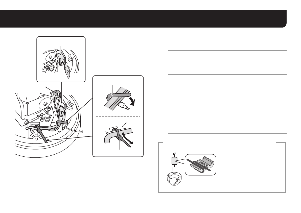
Remove the drop-prevention cord and secure it
4
together with the supplied fixer (blue) using a
screw.
2
3
Spacer
Screw
CN407
COM/NET
Lens assembly
LAN port
1
2
Spacer
Drop-prevention cord
Fixer (blue)
4
LAN cable
5
Note: Confirm that the COM switch on the lens assembly is turned to “N”.
2
Draw the LAN cable through the hole at the
5
bottom of the camera unit.
Set the lens assembly back to the camera unit.
6
Page 3

CN406
CN403
7
LAN port
8
Fixer (blue)
Retainer
Fixer (black)
1. Installing the Option Board
Connect the LAN cable coming out from the hole
7
at the bottom of the camera unit to the LAN port.
Using both the fixer (blue and black), fix the LAN
8
cable and CN406 cable to the cabinet.
Note:
• Thread the fixer (black) through the retainer before fixing the
LAN cable.
• When you use the heater (VA-50H, option board), make sure
that the LAN cable does not contact with the heater.
• Be sure to wire the cables connected to CN403 and CN406 so
that they do not touch the circuit board placed nearby.
Configure the network settings (See next page).
9
To prevent electromagnetic interference
• On the LAN cable
Be sure to attach the supplied
clamping core to the cable as
illustrated.
3
Page 4
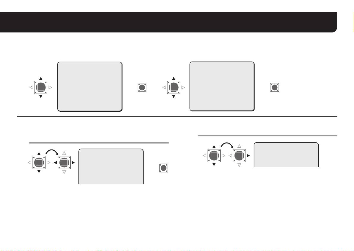
2. Configuring the Network Settings
Configure the settings required for connecting the camera to the network (LAN) in the menu screen.
• For accessing the Main menu, see pages 5 - 7 on the INSTRUCTION MANUAL supplied with the camera.
• After you turn on the power, it takes approximately one minute for the “NETWORK” setting menu to appear on the “OPTION” screen.
SYNC
BLC
IRIS
WHITE BALANCE
AGC GAIN
GAMMA
SHUTTER
APERTURE
DAY/NIGHT
·OPTION
·OPTION
(SET)
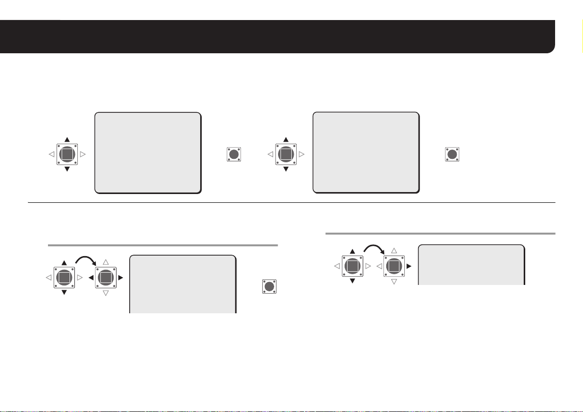
Select “IP ADDRESS”, specify the option for
1
PRESET
MENU
INT
OFF
SET y
ATW
NORM
0.45
60
HIGH
AUTO y
SET y
OFF
END
RR R
retrieving the IP address, and press the SET
button.
NETWORK SETTING
·IP ADDRESS
PORT
·IP ADDRESS
MAC ADDRESS
08-00-7B-81-12-20
FIX : Manual configuration (Default IP address: 192.168.0.2)
AUTO : Automatic configuration (DHCP)
RThe “IP ADDRESS SETTING” screen appears.
The “MAC ADDRESS” cannot be changed.
MEMO:
Confirm the setting.
FIX y
00080
OPTION
TITLE
SET SET
·NETWORK
(SET)
PRIVACY MASK
PASSWORD
ALARM
LANGUAGE
·NETWORK
PRESET
MENU
Select the item to configure, and press the Select
2
OFF
SET y
SET y
SET y
SET y
SET y
OFF
BACK
(c) button.
IP ADDRESS SETTING
·IP ADDRESS
192.168.000.002
x
R
SET
ROnly the item selected appears and “x” is displayed below the
address.
• To display all the items again, press the Select (d or c) button
repeatedly until “x” disappears.
When you select “AUTO” for the “IP ADDRESS” setting in the
MEMO:
“NETWORK SETTING” screen, the IP address cannot be
changed. Confirm the setting, and advance to step
4.
4
Page 5
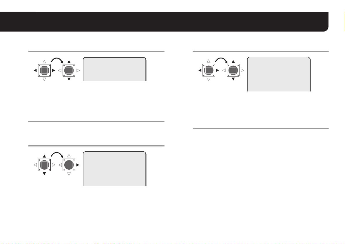
2. Configuring the Network Settings
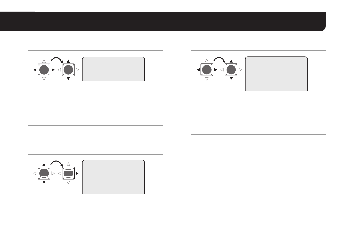
Select the digit to be changed, and specify the
3
value.
IP ADDRESS SETTING
·IP ADDRESS
192.168.000.052
x
• Repeat step 3 as required.
• When you want to change other items, return to step 2 .
Set “MENU” to “BACK” and press the SET
4
button.
RReturns to the “NETWORK SETTING” screen.
Change the port number (0-65535) if required.
5
NETWORK SETTING
IP ADDRESS
·PORT
·PORT
RDisplay “x” below the port number.
When you set the SSL option to ON, “00443” is selected for the
MEMO:
“PORT” setting.
MAC ADDRESS
08-00-7B-81-12-20
FIX y
00080
x
Select the digit to be changed, and specify the
6
value.
NETWORK SETTING
IP ADDRESS
·PORT
MAC ADDRESS
08-00-7B-81-12-20
• Repeat step 6 as required.
• When finished, press the Select (d or c) button repeatedly
until “x” disappears.
Set “MENU” to “END” and press the SET button.
7
RCloses the settings screen and returns to the normal monitoring
screen.
• If you want to return to the previous screen, select “BACK” and
press the SET button.
FIX y
00090
x
5
Page 6

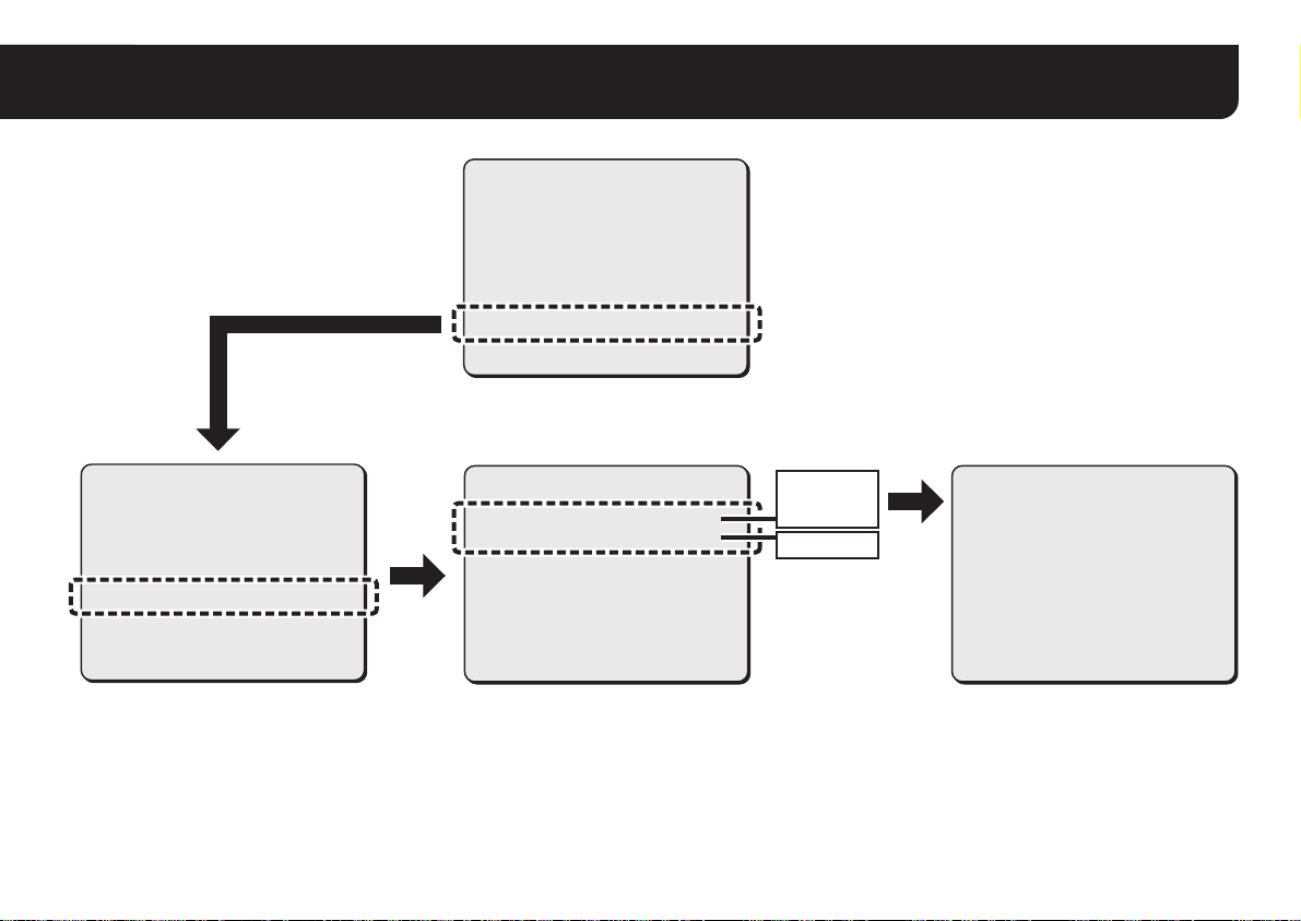
3. Flow of Camera Operation through to Network Operation
Perform the following procedures according to the detailed instructions given in the INSTRUCTION MANUAL [VA-50LAN_MANUAL] contained in
the supplied CD-ROM.
1 Accessing the camera
Enter your user name and password, and then select a language you want to display on the screen.
User name: admin
Password: admin
5
2 Displaying live video from the camera on the main screen
5
3 Configuring the administration settings
Using the [MAIN SETTINGS] screen for an administrative user, configure the detailed settings for administration.
When you access the camera for the first time, be sure to perform the settings on the [CLOCK SETTINGS] screen.
5
4 Changing the camera settings
Changes in the camera settings can be made through the network connection.
MEMO: • After you turn on the power, wait approximately one minute before network connection is established.
• If you have to configure TCP/IP settings for your PC, refer to the VA-50LAN’s INSTRUCTION MANUAL from page 4 onward.
• To view the INSTRUCTION MANUAL contained in the supplied CD-ROM, you need Adobe
been installed with it, you can download it for installation from the following web site at Adobe Systems Incorporated.
http://www.adobe.co.jp/products/acrobat/readstep2.html
®
Reader® application. If your PC has not
Refer to
6
8
11
18
6
Page 7

4. Software Setup Procedure for VA-SW3050LITE
The VA-SW3050LITE software achieves multiple monitoring by using up to 128 cameras and allows frame switchover among several selections
including 4-frame and 16-frame views.
Perform the following procedures according to the detailed instructions given in the INSTRUCTION MANUAL [VA-SW3050LITE_MANUAL]
contained in the supplied CD-ROM.
1 Installing the VA-SW3050LITE software (refer to the next page)
5
2 Starting the VA-SW3050LITE software and perform the login procedure
Double-click the “Network Recorder” shortcut icon created on the desktop.
USER ID: admin
PASSWORD: admin
5
3 Registering the camera(s) with the software
Register the camera(s) to access, and configure the camera settings such as IP address and camera title.
5
4 Displaying live video from the camera on the main screen
MEMO: After you turn on the power, wait approximately one minute before you can login.
Refer to
5
7
10
7
Page 8

Installing the VA-SW3050LITE Software
Start the installation program from the software CD, and use the interactive dialog boxes to advance the installation process.
Double-click “Setup.exe” contained in the supplied
1
CD-ROM.
The “Welcome to the InstallShield Wizard for
2
VA-SW3050LITE” dialog appears.
Click [Next].
The “License Agreement” dialog appears.
3
Select the “I accept the agreement” option and then click [Next].
The “Select Destination Location” dialog appears.
4
Click [Next].
• To change the destination folder in which you want to save the
VA-SW3050LITE software, click [Browse] and select the
desired folder. You may also type the folder name directly in the
box.
The “Select Start Menu Folder” dialog appears.
5
Click [Next].
• To change the start menu folder, click [Browse] and select the
desired folder. You may also type the folder name directly in the
box.
The “Ready to Install” dialog appears.
6
Click [Install].
RInstalling
The “Completing the VA-SW3050LITE Setup Wizard”
7
dialog appears.
Click [Finish].
RNow you have installed the VA-SW3050LITE software
successfully. You will find the “Network Recorder” short cut icon
on the desktop.
MEMO:
• Microsoft .NET Framework 1.1 is required to use the
VA-SW3050LITE software. If your PC has not been installed
with it, an automatic installation program will show you a
confirmation dialog box to start its setup process, when
you double-click “Setup”. It will be about two minutes
before the installation program finishes.
• Once the installation is finished, you may be prompted to
restart the PC. Follow the instructions that may appear on
the screen.
8
Page 9
Specifications
Power
consumption
Power source Supplied from main unit
Weight
(approx.)
Accessory
Appearance and specifications are subject to change without prior notice
or obligations.
9.5 W (with the option board installed)
Max. 23 W (with heater turned on: VA-50H, option
board)
50 g (1.8 oz)
Screw................................................................... 3
Fixer (blue/black) ........................................ each 1
Clamping core......................................................1
CD-ROM (VA-SW3050LITE)................................ 1
■ License for Software Contained in CD-ROM
• Please read carefully the terms and conditions contained in the
license agreement that appears on the screen during the software
installation process. Provided that you have agreed to all the terms
and conditions therein, you may use the software subject to the
license agreement.
• For information on the other products or services provided by third
parties which are introduced in the CD-ROM, please contact each
supplier or manufacturer.
■ Copyright notice
This instruction manual is copyrighted by SANYO Electric Co., Ltd.
No materials contained in this manual may be reproduced in any format
without the prior permission of the copyright holder.
Microsoft, Windows and Internet Explorer are registered trademarks or
trademarks of Microsoft Corporation in the United States and other
countries.
The official name for “Windows” used in this manual is Microsoft
Windows
“Windows” refers to both “Microsoft
and “Microsoft
Intel and Pentium are registered trademarks or trademarks of Intel
Corporation and its subsidiaries in the United States and other countries.
IBM and IBM PC/AT are trademarks of International Business Machines
Corporation.
Adobe Reader is a trademark of Adobe Systems Incorporated.
UPnP is a trademark of UPnP Implementers Corporation, which is
established by the UPnP Forum SC.
Java is a trademark of Sun Microsystems, Inc.
All other brands and product names in this manual are the registered
trademarks or trademarks of their respective owners.
®
Operating System. In this manual, note that the word
®
Windows® XP Operating System”.
®
Windows® 2000 Operating System”
®
9
Page 10
Screen Sequence
OPTION
TITLE
PRIVACY MASK
PASSWORD
ALARM
LANGUAGE
·NETWORK
PRESET
MENU
OFF
SET y
SET y
SET y
SET y
SET y
OFF
BACK
SYNC
BLC
IRIS
WHITE BALANCE
AGC GAIN
GAMMA
SHUTTER
APERTURE
DAY/NIGHT
·OPTION
PRESET
MENU
NETWORK SETTING
·IP ADDRESS
PORT
MAC ADDRESS
08-00-7B-81-12-20
MENU
INT
OFF
SET y
ATW
NORM
0.45
60
HIGH
AUTO y
SET y
OFF
END
FIX y
00080
BACK
AUTO
FIX
0-65535
IP ADDRESS SETTING
·IP ADDRESS
192.168.000.002
SUBNET MASK
255.255.255.000
GATEWAY
192.168.000.001
MENU
BACK
10
Page 11
INSTALLATIONSANLEITUNG
Optionskarte (Netzwerk)
Zu dieser Anleitung
Lesen Sie bitte diese Anleitung vor der Installation und Verwendung dieser Einheit sorgfältig durch
und befolgen Sie die Anweisungen für den richtigen Gebrauch.
VA-50LAN
■ Direkter Anschluss
Schließen Sie die Kamera mit einem
LAN-Kabel (Crossover-Kabel) an Ihren PC an.
PC
LAN-Netzwerkkabel
(Crossover-Kabel)
■ LAN-Anschluss
Schließen Sie die Kamera über ein
Umschalt-Hub mit LAN-Kabeln
(Patchkabeln) an das LAN-Netzwerk an.
Umschalt-Hub
LAN-Netzwerkkabel
(Patchkabel)
■ Systemanforderungen
Die Systemvoraussetzungen für den Kamerabetrieb über das Netzwerk sind wie folgt:
•PC: IBM PC/AT und kompatible Modelle
• Betriebssystem: Windows 2000/Windows XP
•CPU: Pentium III (800 MHz oder höher)
• Arbeitsspeicher: mindestens 128 MB
* Geschirmte LAN-Netzwerkkabel verwenden.
Home Edition/Windows XP
Professional
• Netzwerk-Schnittstelle: 10Base-T/100Base-TX
• Grafikkarte: Mindestens 1024 x 768 Bildpunkte
• Internet-Browser: Internet Explorer Version 6.0
Mindestens 16 Millionen Farben
oder höher
LAN
■ Internet-Anschluss
Verbinden Sie die Kamera mithilfe von
LAN-Kabeln mit einem Router oder
ADSL-Modem mit LAN-Schnittstelle.
Verwenden Sie Patch-Netzwerkkabel,
wenn Sie einen Router anschließen.
Bei Anschluss an ein ADSL-Modem oder
andere Geräte, wird auf
die Bedienungsanleitung
des angeschlossenen Geräts verwiesen.
Router oder
ADSL-Modem
Internet
English Deutsch Français Español
中文简体
日本語
Page 12
1. Installieren der Optionskarte
Nehmen Sie die Abdeckkappe und dann die Objektiveinheit ab. Bringen Sie die Abdeckkappe nach Abschluss
der Einstellungen wieder an.
• Für weitere Einzelheiten siehe INSTALLATIONSANLEITUNG der Kamera.
Schließen Sie das Steckerkabel der Optionskarte
1
CN407
COM/NET
Objektiveinheit
Fallsicherungsband
Kabelbinder
4
Distanzstück
2
Schraube
3
Hinweis: Überprüfen Sie, dass der COM-Schalter auf der
Objektiveinheit auf „N“ geschaltet ist.
2
Distanzstück
LAN-Port
1
(blau)
LAN-Netzwerkkabel
5
an den COM/NET-Anschluss auf der Rückseite
der Objektiveinheit an.
Setzen die Distanzstücke an der Optionskarte
2
in die Objektiveinheit ein (2 x).
Befestigen Sie die Optionskarte von
3
der Rückseite mithilfe der Schrauben, die mit
der Optionskarte mitgeliefert werden (3 x).
Das Fallsicherungsband entfernen und mit einer
4
Schraube zusammen mit dem mitgelieferten
Kabelbinder (blau) befestigen.
Ziehen Sie das LAN-Kabel durch die Öffnung
5
im Boden der Kameraeinheit.
Bringen Sie die Objektiveinheit wieder
6
an der Kamera an.
2
Page 13
7
LAN-Port
1. Installieren der Optionskarte
Verbinden Sie das durch die Öffnung im Boden
7
der Kameraeinheit kommende LAN-Kabel
mit dem LAN-Anschluss.
Befestigen Sie das LAN-Kabel und das
8
CN406-Kabel mit den beiden Kabelbindern (blau
und schwarz) am Gehäuse.
CN406
CN403
Kabelbinder (blau)
8
Halter
Kabelbinder (schwarz)
Hinweis:
• Führen Sie den Kabelbinder (schwarz) durch den Halter, bevor Sie das
LAN-Kabel befestigen.
• Wenn Sie die Heizung (Optionskarte, VA-50H) verwenden, vergewissern
Sie sich, dass das LAN-Kabel die Heizung nicht berührt.
• Achten Sie darauf, die an die Anschlüsse CN403 und CN406
angeschlossenen Kabel so zu verlegen, dass diese die in der
Nähe angebrachte Schaltplatine nicht berühren.
Konfigurieren Sie die Netzwerkeinstellungen
9
(siehe folgende Seite).
Vermeiden von elektromagnetischen Störungen
• Am LAN-Netzwerkkabel Den mitgelieferten Ferritkern
wie abgebildet an den
Anschlusskabel anbringen.
3
Page 14
2. Konfiguration der Netzwerkeinstellungen
Konfigurieren Sie im entsprechenden Menüfenster die Einstellungen, die für den Anschluss der Kamera an das Netzwerk
(LAN) erforderlich sind.
• Zum Aufrufen des Hauptmenüs siehe Seite 5 - 7 in der BEDIENUNGSANLEITUNG der Kamera.
• Nach dem Einschalten dauert es etwa eine Minute bis das Einstellmenü „NETZWERK“ im Fenster „OPTION“ angezeigt wird.
SYNC
BLC
IRIS
WEISSABGLEICH
AGC VERSTAERK.
GAMMA
VERSCHLUSSZEIT
BLENDE
TAG/NACHT
·OPTION
·OPTION
(EINST)
Wählen Sie „IP-ADRESSE“, wählen Sie die
1
VOREINST.
MENUE
INT
AUS
EINSTy
ATW
NORM
0.45
60
HOCH
AUTO y
EINSTy
AUS
ENDE
Option für das Abrufen der IP-Adresse und
drücken Sie die Taste SET.
NETZWERK EINST.
·IP-ADRESSE
PORT
·IP-ADRESSE
MAC-ADRESSE
08-00-7B-81-12-20
FEST : Manuelle Konfiguration (Standard-IP-Adresse:
192.168.0.2)
AUTO : Automatische Konfiguration (DHCP)
RDer Bildschirm „IP-ADRESSE EINST.“ wird angezeigt.
Die „MAC-ADRESSE“ kann nicht geändert werden.
MEMO:
Überprüfen Sie die Einstellung.
4
OPTION
BEZEICHNUNG
SET SET
RR R
·NETZWERK
(EINST)
PRIV.MASK.
KENNWORT
ALARM
SPRACHE
·NETZWERK
VOREINST.
MENUE
Wählen Sie den zu konfigurierenden Menüpunkt
2
AUS
EINSTy
EINSTy
EINSTy
EINSTy
EINSTy
AUS
ZURUECK
und drücken Sie die Auswahltaste (c).
IP-ADRESSE EINST.
·IP-ADRESSE
FESTy
00080
R
SET
RNur der gewählte Menüpunkt wird angezeigt und „x“ wird unter
der Adresse eingeblendet.
• Drücken Sie zur erneuten Anzeige aller Menüpunkte mehrmals
die Auswahltaste (d oder c) bis „x“ verschwindet.
Wenn Sie für die „IP-ADRESSE“ im Menü „NETZWERK EINST.“
MEMO:
die Option „AUTO“ auswählen, kann die IP-Adresse nicht geändert
werden. Überprüfen Sie die Einstellung und gehen Sie weiter zu
4.
Schritt
192.168.000.002
x
Page 15
2. Konfiguration der Netzwerkeinstellungen
Wählen Sie die zu ändernde Ziffer aus und legen
3
Sie den Wert fest.
IP-ADRESSE EINST.
·IP-ADRESSE
192.168.000.052
x
• Wiederholen Sie Schritt 3 nach Bedarf.
• Wenn Sie weitere Menüpunkte ändern möchten, gehen Sie
zurück zu Schritt
„MENUE“ auf „ZURUECK“ einstellen und die
4
2.
SET-Taste drücken.
RDamit wird zum Bildschirm „NETZWERK EINST.“
zurückgeschaltet.
Ändern Sie ggf. die Port-Nummer (0-65535).
5
NETZWERK EINST.
IP-ADRESSE
·PORT
·PORT
RAnzeige „x“ unter der Port-Nummer.
Wenn Sie für die Option SSL EIN wählen, wird für die Einstellung
MEMO:
„PORT“ der Wert „00443“ ausgewählt.
MAC-ADRESSE
08-00-7B-81-12-20
FESTy
00080
x
Wählen Sie die zu ändernde Ziffer aus und legen
6
Sie den Wert fest.
NETZWERK EINST.
IP-ADRESSE
·PORT
MAC-ADRESSE
08-00-7B-81-12-20
• Wiederholen Sie Schritt 6 nach Bedarf.
• Drücken Sie nach Abschluss der Einstellungen mehrmals die
Auswahltaste (d oder c) bis „x“ verschwindet.
„MENUE“ auf „ENDE“ einstellen und die
7
FESTy
00090
x
SET-Taste drücken.
RSchließt den Einstellbildschirm und schaltet zum normalen
Monitorbildschirm zurück.
• Um auf den vorhergehenden Bildschirm zurückzuschalten,
stellen Sie „ZURUECK“ ein und drücken Sie die SET-Taste.
5
Page 16
3. Ablauf der Kamerabedienung durch Netzwerkbetrieb
Gehen Sie wie im Folgenden beschrieben vor und schlagen Sie zu diesem Zweck in der detaillierten BEDIENUNGSANLEITUNG
[VA-50LAN_MANUAL] nach, die auf der mitgelieferten CD-ROM enthalten ist.
Siehe
1 Zugriff auf die Kamera
Geben Sie Benutzername und Kennwort ein und wählen Sie anschließend eine Sprache für die Anzeige auf dem
Bildschirm aus.
Benutzername: admin
Kennwort: admin
5
2 Wiedergabe von Live-Videobildern von der Kamera auf dem Hauptbildschirm
5
3 Konfiguration der Administratoreinstellungen
Konfigurieren Sie die detaillierten Einstellungen für einen Administrator im Menü [HAUPTEINSTELLUNGEN].
Vergessen Sie nicht, die Einstellungen im Menü [UHREINSTELLUNGEN] vorzunehmen, wenn Sie zum ersten Mal auf
die Kamera zugreifen.
5
4 Ändern der Kameraeinstellungen
Änderungen an den Kameraeinstellungen können über die Netzwerkverbindung vorgenommen werden.
MEMO: • Warten Sie nach dem Einschalten etwa eine Minute bis die Netzwerkverbindung hergestellt wurde.
• Wenn Sie TCP/IP-Einstellungen für Ihren PC konfigurieren müssen, schlagen Sie in der BEDIENUNGSANLEITUNG für VA-50LAN ab
Seite 4 nach.
• Zum Öffnen der BEDIENUNGSANLEITUNG auf der mitgelieferten CD-ROM benötigen Sie das Programm Adobe
Anwendung nicht auf Ihrem PC installiert ist, können Sie das Programm unter der nachstehend angegebenen Internet-Adresse bei
Adobe Systems Incorporated zur Installation herunterladen:
http://www.adobe.co.jp/products/acrobat/readstep2.html
®
Reader®. Falls diese
6
8
11
18
6
Page 17

4.
Vorgehensweise zum Einrichten der Software VA-SW3050LITE
Das Programm VA-SW3050LITE kann für die Überwachung von bis zu 128 Kameras verwendet werden und gestattet unter anderem das
Umschaltenzwischen Einzelbildern sowie die Mehrfachbildanzeige mit 4 bis 16 Bildern.
Gehen Sie wie im Folgenden beschrieben vor und schlagen Sie zu diesem Zweck in der detaillierten BEDIENUNGSANLEITUNG
[VA-SW3050LITE_MANUAL] nach, die auf der mitgelieferten CD-ROM enthalten ist.
1 Installation des Programms VA-SW3050LITE (siehe folgende Seite)
5
2 Starten des Programms VA-SW3050LITE und Anmeldevorgang
Doppelklicken Sie das auf dem Desktop erstellte Verknüpfungssymbol „Network Recorder“ an.
USER ID: admin
PASSWORD: admin
5
3 Registrieren der Kamera(s) mit der Software
Registrieren Sie die Kamera(s), auf die Sie zugreifen möchten, und konfigurieren Sie die Kameraeinstellungen
(z.B. IP-Adresse und Kamerabezeichnung).
5
4 Wiedergabe von Live-Videobildern von der Kamera auf dem Hauptbildschirm
MEMO: Warten Sie nach dem Einschalten etwa eine Minute bis die Anmeldung möglich ist.
Siehe
5
7
10
7
Page 18

Installation des Programms VA-SW3050LITE
Starten Sie das Installationsprogramm von der Software-CD und benutzen Sie die interaktiven Dialogfelder für den Installationsvorgang.
Doppelklicken Sie auf die Datei „Setup.exe“ auf der
1
mitgelieferten CD-ROM.
Das Dialogfeld „Welcome to the InstallShield Wizard
2
for VA-SW3050LITE“ wird geöffnet.
Klicken Sie auf [Next].
Das Dialogfeld „License Agreement“ erscheint.
3
Wählen Sie die Option „I accept the agreement“ und klicken Sie
anschließend auf [Next].
Das Dialogfeld „Select Destination Location“ wird
4
geöffnet.
Klicken Sie auf [Next].
• Klicken Sie zum Ändern des Zielordners, in dem das Programm
VA-SW3050LITE gespeichert werden soll, auf [Browse] und
wählen Sie den gewünschten Ordner aus. Der Ordnername
kann auch direkt in das Feld eingegeben werden.
Das Dialogfeld „Select Start Menu Folder“ wird
5
geöffnet.
Klicken Sie auf [Next].
• Klicken Sie zum Ändern des Ordners im Startmenü auf
[Browse] und wählen Sie den gewünschten Ordner. Der
Ordnername kann auch direkt in das Feld eingegeben werden.
Das Dialogfeld „Ready to Install“ wird geöffnet.
6
Klicken Sie auf [Install].
RInstallation
Das Dialogfeld „Completing the VA-SW3050LITE Setup
7
Wizard“ wird geöffnet.
Klicken Sie auf [Finish].
RDie Software VA-SW3050LITE wurde nun erfolgreich installiert.
Sie finden das Verknüpfungssymbol „Network Recorder“ auf
dem Desktop.
MEMO:
• Für die Nutzung des Programms VA-SW3050LITE wird
Microsoft .NET Framework 1.1 benötigt. Falls diese
Anwendung nicht auf Ihrem PC installiert ist, wird ein
Dialogfeld für die Bestätigung der automatischen
Installation des Programms geöffnet, um den
Installationsvorgang durch doppelklicken auf „Setup“ zu
starten. Für die Installation des Programms werden etwa
zwei Minuten benötigt.
• Nach Abschluss der Installation werden Sie ggf. zu einem
Neustart des PC’s aufgefordert. Befolgen Sie die
Anweisungen, die ggf. auf dem Bildschirm angezeigt
werden.
8
Page 19

Technische Daten
Leistungsaufnahme
Stromquelle Versorgung durch das Hauptgerät
Gewicht (ungefähr) 50 g (1,8 oz)
Zubehör
Änderungen des Aussehens und der technischen Daten ohne
Vorankündigung oder sonstige Verpflichtungen bleiben vorbehalten.
9,5 W (mit installierter Optionskarte)
Max. 23 W (bei eingeschalteter Heizung:
VA-50H, Optionskarte)
Schrauben ...................................................3
Kabelbinder (blau/schwarz).....................je 1
Ferritkerns ...................................................1
CD-ROM (VA-SW3050LITE).......................1
■ Lizenz für die auf der CD-ROM enthaltene Software
• Lesen Sie bitte sorgfältig die in der Lizenzvereinbarung enthaltenen
Bedingungen und Bestimmungen, die während dem
Installationsvorgang der Software auf dem Bildschirm angezeigt
werden. Unter der Voraussetzung, dass Sie allen hierin enthaltenen
Bedingungen und Bestimmungen zugestimmt haben, können Sie die
Software gemäß der Lizenzvereinbarung nutzen.
• Wenden Sie sich bitte für Informationen zu anderen Produkten oder
Dienstleistungen, die durch auf der CD-ROM angegebene Dritte
bereitgestellt werden, an den jeweiligen Lieferanten oder Hersteller.
■ Hinweis zum Urheberrecht
Diese Anleitung unterliegt dem Urheberrecht der SANYO Electric Co.,
Ltd.
Sämtliche in diesem Handbuch enthaltenen Materialien dürfen ohne
vorherige Genehmigung durch den Inhaber des Urheberrechts in keiner
Weise reproduziert werden.
Microsoft, Windows und Internet Explorer sind eingetragene
Warenzeichen oder Warenzeichen der Microsoft Corporation in den
USA und in anderen Ländern.
Eine offizielle Bezeichnung für „Windows“, die in diesem Handbuch
verwendet wird, ist das Betriebssystem Microsoft
beachten, dass sich in diesem Handbuch das Wort „Windows“ sowohl
auf das Betriebssystem „Microsoft
Betriebssystem „Microsoft
Intel und Pentium sind eingetragene Warenzeichen oder Warenzeichen
der Intel Corporation und ihren Tochtergesellschaften in den USA und in
anderen Ländern.
IBM und IBM PC/AT sind Warenzeichen der IBM International Business
Machines Corporation.
Adobe Reader ist ein Warenzeichen der Adobe Systems Incorporated.
UPnP ist ein Warenzeichen der UPnP Implementers Corporation,
gehalten durch das UPnP-Forum SC.
Java ist ein Warenzeichen der Sun Microsystems, Inc.
Bei allen weiteren in diesem Handbuch erwähnten Marken- und
Produktnamen handelt es sich um die Markenbezeichnungen und
registrierten Warenzeichen ihrer jeweiligen Eigentumsgesellschaften.
®
®
Windows® 2000“ als auch auf das
Windows® XP“ bezieht.
®
Windows®. Es ist zu
9
Page 20

Menüfolge
OPTION
BEZEICHNUNG
PRIV.MASK.
KENNWORT
ALARM
SPRACHE
·NETZWERK
VOREINST.
MENUE
AUS
EINSTy
EINSTy
EINSTy
EINSTy
EINSTy
AUS
ZURUECK
SYNC
BLC
IRIS
WEISSABGLEICH
AGC VERSTAERK.
GAMMA
VERSCHLUSSZEIT
BLENDE
TAG/NACHT
·OPTION
VOREINST.
MENUE
NETZWERK EINST.
·IP-ADRESSE
PORT
MMAC-ADRESSE
08-00-7B-81-12-20
MENUE
INT
AUS
EINSTy
ATW
NORM
0.45
60
HOCH
AUTO y
EINSTy
AUS
ENDE
FESTy
00080
ZURUECK
AUTO
FEST
0-65535
IP-ADRESSE EINST.
·IP-ADRESSE
192.168.000.002
SUBNETZMASKE
255.255.255.000
GATEWAY
192.168.000.001
MENUE
ZURUECK
10
Page 21

MANUEL D’INSTALLATION
Carte optionnelle (Réseau)
A propos de ce manuel
Avant d’installer et d’utiliser cette unité, veuillez lire avec attention le présent manuel
et respectez toujours les instructions d’utilisation fournies.
VA-50LAN
■ Connexion directe
Reliez la caméra à votre ordinateur
personnel en utilisant un câble LAN (de type
croisé).
Ordinateur
personnel
Câble LAN
(croisé)
■ Connexion LAN
Reliez la caméra au réseau local (LAN) via
un concentrateur de commutation en
utilisant des câbles LAN (de type droit).
Concentrateur de
commutation
Câble LAN
(droit)
LAN
■ Conditions de système requises
Les conditions de système requises pour le fonctionnement de la caméra via réseau sont les
suivantes :
Ordinateur personnel : IBM PC/AT et compatibles
•
• Système d’exploitation : Windows 2000/
• Unité centrale :
* Utilisez des câbles LAN blindés.
Windows XP Home
Edition/Windows XP
Professional
Pentium III (800 MHz ou supérieur)
• Mémoire : 128 Mo ou plus
• Interface réseau : 10Base-T/100Base-TX
• Carte d'affichage : 1024 x 768 pixels ou plus,
16 millions de couleurs ou plus
• Explorateur Web : Internet Explorer Version 6.0
ou supérieure
■ Connexion Internet
Reliez la caméra à un routeur ou un modem
ADSL avec interface LAN en utilisant des
câbles LAN.
Pour la connexion à un routeur, utilisez
un câble LAN de type droit.
Pour la connexion à un modem ADSL ou
à d’autres dispositifs, reportez-vous au
manuel d’instructions du dispositif
concerné.
Routeur ou
modem ADSL
Internet
English Deutsch Français Español
中文简体
日本語
Page 22

1. Installation de la carte optionnelle
Otez le couvercle du dôme puis l’ensemble objectif. Une fois les réglages effectués, remettez le couvercle du dôme en
place.
• Veuillez vous reporter au MANUEL D'INSTALLATION fourni avec la caméra.
Branchez le câble avec connecteur à broches de
1
CN407
COM/NET
Ensemble objectif
la carte optionnelle sur la borne COM/NET située
à l’arrière de l'ensemble objectif.
Cordon anti-chute
Elément de
4
fixation (bleu)
2
Pièce
d'écartement
Port LAN
1
Câble LAN
5
Pièce
d’écartement
2
Vis
3
Remarque : Assurez-vous que l’interrupteur COM situé sur l’ensemble
2
objectif est réglé sur « N ».
Emboîtez les pièces d'écartement de la carte
2
optionnelle dans l’ensemble objectif
(2 emplacements).
Fixez la carte optionnelle par l’arrière au moyen
3
des vis fournies avec la carte elle-même
(3 emplacements).
Enlevez le cordon anti-chute et fixez-le au moyen
4
d’une vis avec l’élément de fixation (bleu) fourni.
Faites passer le câble LAN à travers le trou situé
5
dans la partie inférieure du groupe caméra.
Replacez l’ensemble objectif sur le groupe
6
caméra.
Page 23

CN406
CN403
7
Port LAN
Elément de fixation
8
(bleu)
Elément de retenue
Elément de fixation (noir)
1. Installation de la carte optionnelle
Branchez le câble LAN sortant du trou situé dans
7
la partie inférieure du groupe caméra dans le port
LAN.
En utilisant les deux éléments de fixation (le bleu
8
et le noir), fixez le câble LAN et le câble CN406 au
boîtier.
Remarque :
• Enfilez l’élément de fixation (noir) dans l’élément de retenue avant de
fixer le câble LAN.
• Si vous utilisez le dispositif de chauffage (carte optionnelle VA-50H),
assurez-vous que le câble LAN n'est pas en contact avec le dispositif de
chauffage.
• Veillez à ce que les câbles branchés sur CN403 et sur CN406
ne touchent pas la carte de circuit imprimé située à proximité.
Configurez les réglages de réseau (Voir page
9
suivante).
Pour empêcher les interférences
électromagnétiques
• Sur le câble LAN Veillez à bien fixer le noyau
de ferrite fourni aux câble
comme le montre la figure.
3
Page 24

2. Configuration des réglages de réseau
Dans l’écran de menu, configurez les réglages requis pour la connexion de la caméra au réseau (LAN).
• Pour accéder au menu principal, reportez-vous aux pages 5 - 7 du MANUEL D’INSTRUCTIONS fourni avec la caméra.
• Après avoir mis l’unité sous tension, il faudra attendre une minute environ avant que le menu de réglage « RESEAU » apparaisse sur l’écran
«OPTION».
SYNC
BLC
IRIS
EQUIL BLANC
GAIN CAG
GAMMA
VIT OBTURATEUR
OUVERTURE
JOUR/NUIT
·OPTION
·OPTION
(REG)
Sélectionnez « ADRESSE IP », spécifiez l’option
1
PREREGLAGE
MENU
INT
ARR
REG y
ATW
NORM
0.45
60
HAUT
AUTO y
REG y
ARR
FIN
SET SET
RR R
définissant l’adresse IP et appuyez sur le bouton
SET.
REGLAGE RESEAU
·ADRESSE IP
·ADRESSE IP
PORT
ADRESSE MAC
08-00-7B-81-12-20
FIX y
00080
FIX : Configuration manuelle (Adresse IP par défaut :
192.168.0.2)
AUTO : Configuration automatique (DHCP)
RL’écran « REG.ADRESSE IP » s’affiche.
L’« ADRESSE MAC » ne peut pas être modifiée.
N.B. :
Confirmez le réglage.
4
SET
R
·RESEAU
(REG)
OPTION
TITRE
MASQUE
M/PASSE
ALARME
LANGUE
·RESEAU
PREREGLAGE
MENU
Sélectionnez l’élément à configurer et appuyez
2
ARR
REG y
REG y
REG y
REG y
REG y
ARR
RETOUR
sur le bouton de sélection (c).
REG.ADRESSE IP
·ADRESSE IP
192.168.000.002
x
RSeul l’élément sélectionné apparaît et « x » s’affiche sous
l’adresse.
• Pour afficher de nouveau tous les éléments, appuyez plusieurs
fois sur le bouton de sélection (d ou c) jusqu’à ce que « x »
disparaisse.
Lorsque vous sélectionnez « AUTO » pour le paramètre
N.B. :
« ADRESSE IP » dans l’écran « REGLAGE RESEAU », l’adresse IP
ne peut pas être modifiée. Confirmez le réglage et passez au point
4.
Page 25

2. Configuration des réglages de réseau
Sélectionnez le chiffre à modifier et spécifiez
3
une valeur.
REG.ADRESSE IP
·ADRESSE IP
192.168.000.052
x
• Répétez si nécessaire le point 3.
• Pour modifier d’autres éléments, revenez au point 2.
Réglez « MENU » sur « RETOUR » et appuyez sur
4
le bouton SET.
RL’écran « REGLAGE RESEAU » réapparaît.
Modifiez le numéro du port (0-65535)
5
si nécessaire.
REGLAGE RESEAU
ADRESSE IP
·PORT
·PORT
R« x » s’affiche sous le numéro du port.
Lorsque vous réglez l’option SSL sur MAR, « 00443 »
N.B. :
est sélectionné pour le réglage du « PORT ».
ADRESSE MAC
08-00-7B-81-12-20
FIX y
00080
x
Sélectionnez le chiffre à modifier et spécifiez
6
une valeur.
REGLAGE RESEAU
ADRESSE IP
·PORT
ADRESSE MAC
08-00-7B-81-12-20
• Répétez si nécessaire le point 6.
• Quand vous avez terminé, appuyez plusieurs fois sur le bouton
de sélection (d ou c) jusqu’à ce que « x » disparaisse.
Sélectionnez « FIN » dans « MENU » et appuyez
7
FIX y
00090
x
sur le bouton SET.
RL’écran de réglage se ferme et l’écran normal de contrôle
réapparaît.
• Pour retourner à l’écran précédent, sélectionnez « RETOUR »
et appuyez sur le bouton SET.
5
Page 26

3. Flux de fonctionnement de la caméra par l’intermédiaire d’une opération réseau
Effectuez les procédures suivantes en vous reportant aux instructions détaillées données dans le MANUEL D’INSTRUCTIONS
[VA-50LAN_MANUAL] contenu dans le CD-ROM fourni.
Reportez-vous à
1 Accès à la caméra
Entrez votre nom d’utilisateur et votre mot de passe, puis sélectionnez la langue que vous voulez afficher à l’écran.
Nom d’utilisateur : admin
Mot de passe : admin
5
2 Affichage d’une vidéo en direct de la caméra sur l’écran principal
5
3 Configuration des réglages d’administration
En utilisant l’écran [REGLAGES PRINCIPAUX] pour un utilisateur administratif, configurez les réglages détaillés relatifs à
l’administration.
Lorsque vous accédez à la caméra pour la première fois, veillez à bien effectuer les réglages sur l’écran [REGLAGES
HORLOGE].
5
4 Modification des réglages de la caméra
Vous pouvez modifier les réglages de la caméra par l’intermédiaire de la connexion réseau.
6
8
11
18
N.B. : • Après avoir mis l’unité sous tension, attendez une minute environ avant que la connexion réseau soit établie.
• Si vous avez configuré des paramètres TCP/IP pour votre ordinateur, reportez-vous à la page 4 et suivantes du MANUEL
D’INSTRUCTIONS du VA-50LAN.
• Pour visualiser le MANUEL D’INSTRUCTIONS contenu dans le CD-ROM fourni, l’application Adobe
votre ordinateur a été installé sans cette application, vous pouvez la télécharger depuis le site Web suivant d’Adobe Systems
Incorporated.
http://www.adobe.co.jp/products/acrobat/readstep2.html
6
®
Reader® vous est nécessaire. Si
Page 27

4. Procédure d’installation du logiciel VA-SW3050LITE
Le logiciel VA-SW3050LITE permet une surveillance multiple en utilisant jusqu’à 128 caméras ainsi que la commutation d’images entre
plusieurs sélections incluant des vues à 4 et 16 images.
Effectuez les procédures suivantes en vous reportant aux instructions détaillées données dans le MANUEL D’INSTRUCTIONS
[VA-SW3050LITE_MANUAL] qui est contenu dans le CD-ROM fourni.
1 Installation du logiciel VA-SW3050LITE (reportez-vous à la page suivante)
5
2 Démarrage du logiciel VA-SW3050LITE et exécution de la procédure d’ouverture de
session
Double-cliquez sur l’icône de raccourci « Network Recorder » créée sur le bureau.
USER ID: admin
PASSWORD: admin
5
3 Enregistrement de la ou des caméras avec le logiciel
Enregistrez la ou les caméras auxquelles vous voulez accéder et configurez leurs paramètres tels que Adresse IP et Titre
caméra.
5
4 Affichage d’une vidéo en direct de la caméra sur l’écran principal
N.B. : Après avoir mis l’unité sous tension, attendez une minute environ avant d’effectuer la procédure d’ouverture de session.
Reportez-vous à
5
7
10
7
Page 28

Installation du logiciel VA-SW3050LITE
Lancez le programme d’installation depuis le CD du logiciel, et utilisez les boîtes de dialogue interactives pour faire progresser le processus
d’installation.
Double-cliquez sur le fichier « Setup.exe » contenu
1
dans le CD-ROM fourni.
La boîte de dialogue « Welcome to the InstallShield
2
Wizard for VA-SW3050LITE » s’affiche.
Cliquez sur [Next].
La boîte de dialogue « License Agreement » s’affiche.
3
Sélectionnez l’option « I accept the agreement » et cliquez sur
[Next].
La boîte de dialogue « Select Destination Location »
4
s’affiche.
Cliquez sur [Next].
• Pour changer le dossier de destination dans lequel vous voulez
enregistrer le logiciel VA-SW3050LITE, cliquez sur [Browse] et
sélectionnez le dossier de votre choix. Vous pouvez aussi taper
directement le nom du dossier dans le champ.
La boîte de dialogue « Select Start Menu Folder »
5
s’affiche.
Cliquez sur [Next].
• Pour changer le dossier du menu de démarrage, cliquez sur
[Browse] et sélectionnez le dossier de votre choix. Vous pouvez
aussi taper directement le nom du dossier dans le champ.
8
La boîte de dialogue « Ready to Install » s’affiche.
6
Cliquez sur [Install].
RInstallation
La boîte de dialogue « Completing the VA-SW3050LITE
7
Setup Wizard » s’affiche.
Cliquez sur [Finish].
RL’installation du logiciel VA-SW3050LITE a été exécutée avec
succès. L’icône de raccourci « Network Recorder » doit figurer
sur votre bureau.
N.B. :
• Microsoft .NET Framework 1.1 est requis pour utiliser le
logiciel VA-SW3050LITE. Si votre ordinateur n’a pas été
installé avec, un programme d’installation automatique
affichera une boîte de dialogue vous demandant de
confirmer le démarrage du processus d’installation,
lorsque vous double-cliquez sur « Setup ». L’exécution du
programme d’installation durera deux minutes environ.
• Une fois l’installation exécutée, le programme peut vous
inviter à redémarrer l’ordinateur. Suivez les instructions
qui s’affichent éventuellement à l’écran.
Page 29

Spécifications
Consommati
on d’énergie
Source
d’alimentation
Poids
(environ)
Accessoires
L’aspect et les spécifications peuvent être modifiés sans préavis ou
obligations.
9,5 W (Avec la carte optionnelle installée)
23 W maxi (avec le dispositif de chauffage sous
tension : VA-50H, carte optionnelle)
Fournie depuis l’unité principale
50 g (1,8 oz)
Vis........................................................................3
Élément de fixation (bleu/noir) ........... 1 de chaque
Noyau de serrage.................................................1
CD-ROM (VA-SW3050LITE)................................ 1
■ Licence pour le logiciel contenu dans le CD-ROM
• Veuillez lire avec attention les termes et conditions contenus dans
l’accord de licence qui s’affiche à l’écran durant le processus
d’installation du logiciel. Pour pouvoir utiliser le logiciel faisant l’objet
de l’accord de licence, vous devez accepter tous les termes et
conditions qui y sont contenus.
• Pour obtenir des informations sur les autres produits ou services
fournis par des tiers et présentés dans le CD-ROM, veuillez contacter
chaque fournisseur ou fabricant.
■ Notice de copyright
Le copyright du présent manuel d’instructions appartient à SANYO
Electric Co., Ltd.
Aucun des matériels contenus dans ce manuel ne peut être reproduit,
dans quelque format que ce soit, sans l’autorisation préalable du
détenteur du copyright.
Microsoft, Windows et Internet Explorer sont des marques déposées ou
des marques commerciales de Microsoft Corporation aux Etats-Unis et
dans d’autres pays.
Une appellation officielle du terme « Windows » utilisé dans le présent
manuel est la suivante : système d’exploitation Microsoft
Dans le présent manuel, remarquez que le terme « Windows » utilisé se
réfère aussi bien au « système opérationnel Microsoft
2000 » qu’au « système opérationnel Microsoft
Intel et Pentium sont des marques déposées ou des marques
commerciales d’Intel Corporation et de ses filiales aux Etats-Unis et
dans d’autres pays.
IBM et IBM PC/AT sont des marques commerciales d’International
Business Machines Corporation.
Adobe Reader est une marque commerciale d’Adobe Systems
Incorporated.
UPnP est une marque commerciale d’UPnP Implementers Corporation,
qui est établie par le Comité de Direction du Forum UPnP.
Java est une marque commerciale de Sun Microsystems, Inc.
Les autres marques et noms de produit mentionnés dans le présent
manuel sont tous des marques déposées ou des marques
commerciales de leurs propriétaires respectifs.
®
Windows® XP ».
®
Windows®.
®
Windows®
9
Page 30

Séquence des écrans
OPTION
TITRE
MASQUE
M/PASSE
ALARME
LANGUE
·RESEAU
PREREGLAGE
MENU
ARR
REG y
REG y
REG y
REG y
REG y
ARR
RETOUR
SYNC
BLC
IRIS
EQUIL BLANC
GAIN CAG
GAMMA
VIT OBTURATEUR
OUVERTURE
JOUR/NUIT
·OPTION
PREREGLAGE
MENU
REGLAGE RESEAU
·ADRESSE IP
PORT
ADRESSE MAC
08-00-7B-81-12-20
MENU
INT
ARR
REG y
ATW
NORM
0.45
60
HAUT
AUTO y
REG y
ARR
FIN
FIX y
00080
RETOUR
AUTO
FIX
0-65535
REG.ADRESSE IP
·ADRESSE IP
192.168.000.002
MASQUE SOUS-RESEAU
255.255.255.000
PASSERELLE
192.168.000.001
MENU
RETOUR
10
Page 31

MANUAL DE INSTALACIÓN
Placa opcional (Red)
Acerca de este manual
Antes de instalar y de usar esta unidad leer este manual y seguir las instrucciones del mismo
para asegurar un uso correcto.
VA-50LAN
■ Conexión directa
Conectar la cámara al PC mediante el cable
LAN (tipo cruzado).
■ Conexión LAN
Conectar la cámara a la LAN a través de un
conmutador mediante cables LAN (tipo
recto).
PC
Cable LAN
Conmutador
(cruzado)
Cable LAN
(recto)
LAN
■ Requisitos del sistema
Los requisitos del sistema para el funcionamiento de la cámara a través de la red son los
siguientes:
•PC: IBM PC/AT y compatibles
•SO: Windows 2000/Windows XP Home Edition/
Windows XP Professional
•CPU: Pentium III (800 MHz o superior)
•Memoria: 128 MB o más
• Interfaz de red: 10Base-T/100Base-TX
* Usar cables apantallados LAN.
• Tarjeta de visualización:
• Programa de navegación:
1024 x 768 pixeles o superior,
16 millones de colores o superior
Internet Explorer Versión 6.0 o
superior
■ Conexión Internet
Conectar la cámara a un enrutador o
módem ADSL con interfaz LAN mediante
cables LAN.
Al conectarse a un enrutador, usar el
cable LAN recto.
Al conectarse a un módem ADSL u otros
dispositivos, consultar el manual de
instrucciones del dispositivo.
Enrutador o
módem ADSL
Internet
English Deutsch Français Español
中文简体
日本語
Page 32

1. Instalación de la placa opcional
Quitar la tapa de la cúpula y a continuación el conjunto de la lente. Volver a colocar la tapa de la cúpula una vez
finalizados los ajustes.
• Consultar el MANUAL DE INSTALACIÓN facilitado con la cámara.
Conectar el cable del conector de pines de la
1
CN407
COM/NET
Conjunto de la lente
placa opcional al terminal COM/NET situado en el
lado inverso del conjunto de la lente.
Cuerda de protección
contra caídas
Fijador (azul)
1
Espaciador
2
Tornillo
3
Nota: Asegurarse de que el interruptor COM del conjunto de la lente
está en la posición “N”.
2
2
Espaciador
Puerto LAN
4
Cable LAN
5
Colocar los espaciadores en la placa opcional
2
dentro del conjunto de la lente (2 posiciones).
Fijar la placa opcional por el lado inverso
3
mediante los tornillos suministrados con la placa
opcional (3 posiciones).
Quitar la cuerda de protección contra caídas y
4
fijarla junto con el fijador suministrado (azul)
mediante un tornillo.
Tirar del cable LAN a través del orificio de la
5
parte inferior de la unidad de la cámara.
Volver a colocar el conjunto de la lente en la
6
unidad de la cámara.
Page 33

CN406
CN403
7
Puerto LAN
8
Fijador (azul)
Retén
Fijador (negro)
1. Instalación de la placa opcional
Conectar el cable LAN que sale del orificio de la
7
parte inferior de la unidad de la cámara al puerto
LAN.
Usando ambos fijadores (azul y negro), fijar el
8
cable LAN y el cable CN406 al armario.
Nota:
• Pasar el fijador (negro) a través del retén antes de fijar el cable LAN.
• Si se usa el calentador (placa opcional VA-50H), asegurarse de que el
cable LAN no está en contacto con el calentador.
• Comprobar que los cables conectados a CN403 y CN406 se
han extendido de modo que no tocan la placa de circuito
situada en los alrededores.
Configurar los ajustes de red (ver la página
9
siguiente).
Para prevenir las interferencias
electromagnéticas
• En el cable LAN Asegurarse de fijar el núcleo
de bloqueo suministrado a
los cable como se muestra.
3
Page 34

2. Configuración de los ajustes de red
Configurar los ajustes necesarios para la conexión de la cámara a la red (LAN) en la pantalla del menú.
• Para el acceso al menú principal, ver las páginas de 5 a 7 del MANUAL DE INSTRUCCIONES suministrado con la cámara.
• Tras haber conectado la alimentación eléctrica, será necesario cerca de un minuto para que el menú de ajuste “RED” aparezca en la pantalla
“OPCION”.
SINC
BLC
IRIS
BALANCE BLANCO
GANANCIA AGC
GAMMA
VELO OBTURADOR
APERTURA
DIA/NOCHE
·OPCION
·OPCION
(AJU)
Seleccionar “DIRECCION IP”, especificar la
1
PREAJUSTES
MENU
INT
OFF
AJU y
ATW
NORM
0.45
60
ALTA
AUTO y
AJU y
OFF
FIN
SET SET
RR R
opción para recuperar la dirección IP y pulsar el
botón SET.
AJUSTES RED
·
DIRECCION IP
·DIRECCION IP
PUERTO
DIR. MAC
08-00-7B-81-12-20
FIJAy
00080
FIJA : Configuración manual (Dirección IP predefinida:
192.168.0.2)
AUTO : Configuración automática (DHCP)
RAparece la pantalla “AJUS. DIRECC. IP”.
La “DIR. MAC” no puede cambiarse.
NOTA:
Confirmar el ajuste.
4
R
SET
·RED
(AJU)
OPCION
TITULO
MASCARA PRIV
CONTRASENA
ALARMA
IDIOMA
·RED
PREAJUSTES
MENU
Seleccionar el elemento a configurar y pulsar el
2
OFF
AJU y
AJU y
AJU y
AJU y
AJU y
OFF
ATRAS
botón de selección (c).
AJUS.DIRECC.IP
·DIRECCION IP
192.168.000.002
x
RAparece sólo el elemento seleccionado y se visualiza “x”
debajo de la dirección.
• Para volver a visualizar todos los elementos, pulsar el botón de
selección (d o c) varias veces hasta que “x” desaparece.
Cuando se selecciona “AUTO” en el ajuste “DIRECCION IP” de la
NOTA:
pantalla “AJUSTES RED”, la dirección IP no puede cambiarse.
Confirmar el ajuste y continúe con el punto 4.
Page 35

2. Configuración de los ajustes de red
Seleccionar el dígito a cambiar y especificar
3
el valor.
AJUS.DIRECC.IP
·DIRECCION IP
192.168.000.052
x
• Repetir el punto 3 si es necesario.
• Si se desea cambiar otros elementos, volver al punto 2.
Colocar “MENU” en “ATRAS” y pulsar
4
el botón SET.
RSe vuelve a la pantalla “AJUSTES RED”.
Cambiar el número de puerto (0-65535) si es
5
necesario.
AJUSTES RED
DIRECCION IP
·PUERTO
·PUERTO
RSe visualiza “x” debajo del número del puerto.
Si se ajusta la opción SSL en ON, se selecciona “00443” para el
NOTA:
ajuste “PUERTO”.
DIR. MAC
08-00-7B-81-12-20
FIJAy
00080
x
Seleccionar el dígito a cambiar y especificar
6
el valor.
AJUSTES RED
DIRECCION IP
·PUERTO
DIR. MAC
08-00-7B-81-12-20
• Repetir el punto 6 si es necesario.
• Al terminar, pulsar el botón de selección (d o c) varias veces
hasta que “x” desaparece.
Colocar “MENU” en “FIN” y pulsar el botón SET.
7
RSe cierra la pantalla de ajustes y se vuelve a la pantalla normal
de monitorización.
• Si se desea volver a la pantalla anterior, seleccionar “ATRAS” y
pulsar el botón SET.
FIJAy
00090
x
5
Page 36

3. Flujo de funcionamiento de la cámara a través del funcionamiento de red
Llevar a efecto los siguientes procedimientos siguiendo las instrucciones detalladas que se proporcionan en el MANUAL DE INSTRUCCIONES
[VA-50LAN_MANUAL] contenido en el CD-ROM que se suministra.
Consultar
1 Acceso a la cámara
Escribir el nombre de usuario y la contraseña y a continuación seleccionar el idioma que se desea visualizar en la
pantalla.
Nombre de usuario:admin
Contraseña: admin
5
2 Visualización de imágenes en vivo de la cámara en la pantalla principal
5
3 Configuración de los ajustes de administración
Mediante la pantalla [AJUSTES PRINCIPALES] destinada al usuario administrativo, configurar los ajustes detallados
para la administración.
Cuando se accede a la cámara por primera vez, asegurarse de realizar los ajustes de la pantalla [AJUSTES RELOJ].
5
4 Cambio de los ajustes de la cámara
Los cambios de los ajustes de la cámara pueden realizarse a través de la conexión de red.
NOTA: • Tras haber conectado la alimentación eléctrica, esperar cerca de un minuto para que se establezca la conexión de red.
• Si se tienen que configurar los ajustes TCP/IP del ordenador, consultar el MANUAL DE INSTRUCCIONES de VA-50LAN desde la
página 4 en adelante.
• Para ver el MANUAL DE INSTRUCCIONES contenido en el CD-ROM suministrado, es necesario disponer de la aplicación Adobe
®
. Si el PC no tiene instalada esta aplicación, es posible descargarla para la instalación en el siguiente sitio web en Adobe
Reader
Systems Incorporated.
http://www.adobe.co.jp/products/acrobat/readstep2.html
6
8
11
18
®
6
Page 37

4. Procedimiento de configuración del Software para VA-SW3050LITE
Mediante el software VA-SW3050LITE se logra la monitorización múltiple usando hasta un máximo de 128 cámaras asimismo permite el
cambio de fotogramas entre varias selecciones e incluso imágenes de 4 fotogramas y 16 fotogramas.
Realizar los siguientes procedimientos siguiendo las instrucciones detalladas que se proporcionan en el MANUAL DE INSTRUCCIONES
[VA-SW3050LITE_MANUAL] contenido en el CD-ROM que se suministra.
1 Instalación del software VA-SW3050LITE (consultar la página siguiente)
5
2 Inicio del software VA-SW3050LITE y operación de inicio de sesión
Hacer doble clic en el icono de acceso directo “Network Recorder” creado en el escritorio.
USER ID: admin
PASSWORD: admin
5
3 Registro de la/s cámara/s con el software
Registrar la/s cámara/s para el acceso, y configurar los ajustes de la/s misma/s como dirección IP y el título de la
cámara.
5
4 Visualización de imágenes en vivo de la cámara en la pantalla principal
NOTA: Tras haber conectado la alimentación eléctrica, esperar cerca de un minuto para poder iniciar la sesión.
Consultar
5
7
10
7
Page 38

Instalación del software VA-SW3050LITE
Iniciar el programa de instalación del CD de software y usar los cuadros de diálogo interactivos para avanzar en el proceso de instalación.
Hacer doble clic en “Setup.exe” contenido en el
1
CD-ROM suministrado.
Aparece el cuadro de diálogo “Welcome to the
2
InstallShield Wizard for VA-SW3050LITE”.
Hacer clic en [Next].
Aparece el cuadro de diálogo “License Agreement”.
3
Elegir la opción “I accept the agreement” y a continuación hacer
clic en [Next].
Aparece el cuadro de diálogo “Select Destination
4
Location”.
Hacer clic en [Next].
• Para cambiar la carpeta de destino en el que se desea guardar
el software VA-SW3050LITE hacer clic en [Browse] y
seleccionar la carpeta deseada. Es posible además escribir el
nombre de la carpeta directamente en el cuadro.
Aparece el cuadro de diálogo “Select Start Menu
5
Folder”.
Hacer clic en [Next].
• Para cambiar la carpeta del menú de inicio, hacer clic en
[Browse] y seleccionar la carpeta deseada. Es posible además
escribir el nombre de la carpeta directamente en el cuadro.
Aparece el cuadro de diálogo “Ready to Install”.
6
Hacer clic en [Install].
RInstalación
Aparece el cuadro de diálogo “Completing the
7
VA-SW3050LITE Setup Wizard”.
Hacer clic en [Finish].
RLa instalación del software VA-SW3050LITE se ha llevado a
cabo con éxito. Se encontrará el icono de acceso directo
“Network Recorder” en el escritorio.
NOTA:
• Es necesario disponer de Microsoft .NET Framework 1.1
para poder usar el software VA-SW3050LITE. Si no está
instalado en el PC, un programa de instalación automática
mostrará un cuadro de diálogo de confirmaciónpara iniciar
el proceso de configuración del mismo, cuando se hace
doble clic en “Setup”. El programa de instalación durará
unos dos minutos.
• Al finalizar la instalación, es posible que se pida al usuario
la reinicialización del PC. Seguir las instrucciones que
puedan aparecer en la pantalla.
8
Page 39

Especificaciones
Consumo
eléctrico
Fuente
de alimentación
Peso
(aproximado)
Accesorio
El aspecto y las características técnicas pueden sufrir variaciones sin
previo aviso u obligación.
9,5 W (Con la placa opcional instalada)
Máx. 23 W (con el calentador activado: VA-50H,
placa opcional)
Suministrada por la unidad principal
50 g (1,8 onzas)
Tornillo ............................................................ 3
Fijador (azul/negro) ............................... cada 1
Núcleo de bloqueo .......................................... 1
CD-ROM (VA-SW3050LITE) .......................... 1
■ Licencia para software contenida en CD-ROM
• Por favor, leer atentamente los términos y condiciones contenidos en
el Acuerdo de Licencia que aparece en la pantalla durante el proceso
de instalación del software. El software al que se refiere el acuerdo
de licencia puede usarse con la condición de que se hayan aceptado
los términos y condiciones establecidos en el mismo.
• Para información acerca de otros productos o servicios suministrados
por terceras partes, que se han incluido en el CD-ROM, por favor
contactar con el proveedor o fabricante correspondiente.
■ Aviso de Copyright
Este manual de instrucciones es propiedad intelectual de SANYO
Electric Co., Ltd.
Los materiales contenidos en este manual no pueden reproducirse con
ningún medio sin la previa y expresa autorización del propietario.
Microsoft, Windows e Internet Explorer son marcas o marcas
registradas de Microsoft Corporation en los Estados Unidos y en otros
países.
Un nombre oficial para “Windows” usado en este manual es Microsoft
Windows
“Windows” se refiere a los sistemas operativos “Microsoft
2000 Operating System” y “Microsoft
Intel y Pentium son marcas o marcas registradas de Intel Corporation y
sus filiales en los Estados Unidos y en otros países.
IBM e IBM PC/AT son marcas de IBM International Business Machines
Corporation.
Adobe Reader es una marca de Adobe Systems Incorporated.
UPnP es una marca de UPnP Implementers Corporation, creada por la
junta rectora del Forum UPnP.
Java es una marca de Sun Microsystems, Inc.
Las demás marcas y nombres de productos citados en este manual son
marcas registradas o marcas de sus respectivos propietarios.
®
Operating System. Notar que en este manual la palabra
®
Windows® XP Operating System”.
®
Windows®
®
9
Page 40

Secuencia de pantalla
OPCION
TITULO
MASCARA PRIV
CONTRASENA
ALARMA
IDIOMA
·RED
PREAJUSTES
MENU
OFF
AJU y
AJU y
AJU y
AJU y
AJU y
OFF
ATRAS
SINC
BLC
IRIS
BALANCE BLANCO
GANANCIA AGC
GAMMA
VELO OBTURADOR
APERTURA
DIA/NOCHE
·OPCION
PREAJUSTES
MENU
AJUSTES RED
·DIRECCION IP
PUERTO
DIR. MAC
08-00-7B-81-12-20
MENU
INT
OFF
AJU y
ATW
NORM
0.45
60
ALTA
AUTO y
AJU y
OFF
FIN
FIJAy
00080
ATRAS
AUTO
FIJA
0-65535
AJUS.DIRECC.IP
·DIRECCION IP
192.168.000.002
MASCARA SUBRED
255.255.255.000
GATEWAY
192.168.000.001
MENU
ATRAS
10
Page 41

安装手册
选项板 (网络)
关于本手册
在安装和使用本装置之前,请仔细阅读本手册,并始终遵照本手册中的说明正确使用。
VA-50LAN
■ 直接连接
使用 LAN 电缆 (交叉型)将摄像机连接到
您的 PC 上。
PC
LAN 电缆
(交叉型)
■ 系统要求
通过网络操作摄像机的系统要求如下:
•PC: IBM PC/AT及兼容机
• 操作系统: Windows 2000/Windows XP Home
Edition/Windows XP Professional
•CPU: Pentium III (800MHz或更高)
• 内存:128MB或以上
* 使用屏蔽的 LAN 电缆。
■ LAN连接
使用 LAN 电缆 (直线型)通过交换集线器
将摄像机连接到 LAN。
交换集线器
LAN 电缆
(直线型)
LAN
• 网络接口: 10Base-T/100Base-TX
1024 x 768
• 显卡:
•Web浏览器:Internet Explorer 6.0或更高版本
像素或更高,
16 M
色或更高
■ Internet连接
使用 LAN 电缆通过 LAN 接口将摄像机连接
到路由器或 ADSL 调制解调器。
当连接到路由器时,请使用直线型 LAN
电缆。
当连接到 ADSL 调制解调器或其他设备
时,请参阅该设备的说明手册。
路由器或
ADSL
调制解调器
Internet
English Deutsch Français Español
中文简体
日本語
Page 42

1. 安装选项板
先后取下球罩和镜头组件。 完成设定后,请将球罩还原。
• 请参阅摄像机随附的安装手册。
CN407
COM/NET
镜头组件
将选项板管脚连接器电缆连接到镜头组件背面的
1
COM/NET端子。
将选项板上的垫圈放入镜头组件 (2处)。
2
1
垫圈
2
螺钉
3
注:确认镜头组件上的 COM 开关处于 “N”位置。
2
2
垫圈
LAN端口
4
固定器 (蓝色)
LAN电缆
防脱落挂绳
5
使用选项板随附的螺钉从背面固定选项板
3
(3处)。
卸下防脱落挂绳,然后用螺钉将其与随附的固定器
4
(蓝色)一起固定。
通过摄像机装置底部的孔拉出LAN电缆。
5
将镜头组件重新安装到摄像机装置上。
6
Page 43

CN406
CN403
7
LAN端口
8
固定器 (蓝色)
座圈
固定器 (黑色)
1. 安装选项板
将从摄像机装置底部的孔中拉出的LAN电缆连接到
7
LAN端口。
使用固定器 (蓝色和黑色)将LAN电缆和CN406电
8
缆固定到盒上。
注:
• 固定 LAN 电缆之前,请将固定器 (黑色)穿过座圈。
• 当使用加热器 (VA - 5 0 H ,选项板)时,请确保 LAN 电缆未接触
加热器。
• 请务必卷起连接CN403 和 CN406的电缆,以防其接触到放置在附
近的电路板。
配置网络设定 (请参见下一页)。
9
防止电磁干扰
•LAN电缆上 请务必按图示将随附的卡榫屏蔽
环连接到电缆上。
3
Page 44

2. 配置网络设定
在菜单屏幕中配置将摄像机连接到网络 (LAN) 所需的设定。
• 有关访问主菜单的信息,请参见摄像机随附的说明手册第 5 - 7 页。
• 打开电源后,“NETWORK”设定菜单出现在 “OPTION”屏幕上大约需要一分钟时间。
SYNC
BLC
IRIS
WHITE BALANCE
AGC GAIN
GAMMA
SHUTTER
APERTURE
DAY/NIGHT
·OPTION
·OPTION
(SET)
选择 “IP ADDRESS”,指定用于检索IP地址的选
1
PRESET
MENU
INT
OFF
SET y
ATW
NORM
0.45
60
HIGH
AUTO y
SET y
OFF
END
RR R
项,然后按SET按钮。
NETWORK SETTING
·IP ADDRESS
·IP ADDRESS
PORT
MAC ADDRESS
08-00-7B-81-12-20
FIX y
00080
FIX : 手动配置 (缺省 IP 地址:192.168.0.2)
AUTO : 自动配置 (DHCP)
R“IP ADDRESS SETTING”屏幕随即出现。
备注:“MAC ADDRESS”无法更改。
请确认设置。
4
OPTION
TITLE
SET SET
·NETWORK
(SET)
PRIVACY MASK
PASSWORD
ALARM
LANGUAGE
·NETWORK
PRESET
MENU
选择要配置的项目,然后按 “选择 (c)”按钮。
2
SET
OFF
SET y
SET y
SET y
SET y
SET y
OFF
BACK
IP ADDRESS SETTING
·IP ADDRESS
192.168.000.002
x
R
R仅出现选定的项目,并且地址下面显示 “x”。
• 要重新显示所有项目,请反复按 “选择 (d 或 c)”按钮,直
到“
x”消失。
备注: 在“NETWORK SETTING”屏幕中为 “IP ADDRESS”设定
选择 “AUT O”时,无法更改 IP 地址。 确认设定,然后进入
步骤 4。
Page 45

2. 配置网络设定
选择要更改的数字并指定值。
3
IP ADDRESS SETTING
·IP ADDRESS
192.168.000.052
x
• 根据需要重复步骤 3。
• 当希望更改其他项目时,请返回到步骤2。
将“MENU”设定为 “BACK”,然后按SET按钮。
4
R返回到 “NETWORK SETTING”屏幕。
必要时更改端口号(0-65535)。
5
NETWORK SETTING
IP ADDRESS
·PORT
·PORT
R端口号下面显示 “x”。
备注: 将 SSL 选项设定为 ON 时,为 “PORT”设定选择 “00443”。
MAC ADDRESS
08-00-7B-81-12-20
FIX y
00080
x
选择要更改的数字并指定值。
6
NETWORK SETTING
IP ADDRESS
·PORT
MAC ADDRESS
08-00-7B-81-12-20
• 根据需要重复步骤 6。
• 完成后,反复按 “选择”按钮 (d 或 c), 直 到 “
将“MENU”设定为 “END”,然后按SET按钮。
7
R关闭设定屏幕,返回正常监控屏幕。
• 如果希望返回前一屏幕,请选择 “BACK”然后按 SET 按钮。
FIX y
00090
x
x”消失。
5
Page 46

3. 摄像机操作到网络操作流程
参阅随附光盘中包含的说明手册 [VA-50LAN_MANUAL],并按其中给出的详细说明执行以下步骤。
1 访问摄像机
输入您的用户名和密码,然后选择您要在屏幕上显示的语言。
用户名: admin
密码: admin
5
2 在主屏幕上显示来自摄像机的实况视频 8
5
3 配置管理设置
使用管理员用户的[MAIN SETTINGS]屏幕,配置详细的管理设置。
在第一次访问摄像机时,请务必在[CLOCK SETTINGS]屏幕上进行设置。
5
4 更改摄像机设置
通过网络连接可以更改摄像机设置。
备注: • 打开电源后,需要等待大约一分钟时间,然后才能建立网络连接。
• 如果必须为您的 PC 配置 TCP/IP 设定,请参阅 VA - 5 0 L A N 说明手册从第 4 页开始的说明。
• 要查看随附光盘中包含的说明手册,您需要安装有 Adobe
Systems Incorporated 的以下网站下载并进行安装。
http://www.adobe.co.jp/products/acrobat/readstep2.html
®
Reader®应用程序。如果您的 PC 上没有安装此应用程序,则您可以从 Adobe
参阅
6
11
18
6
Page 47

4. VA-SW3050LITE 的软件设置过程
VA-SW3050LITE 软件可以通过使用最多 128 个摄像机来完成多个监控,并且允许在包括 4 帧和 16 帧视图的多个选项之间进行帧转换。
参阅随附光盘中包含的说明手册 [VA-SW3050LITE_MANUAL],并按其中给出的详细说明执行以下步骤。
1 安装VA-SW3050LITE软件 (请参阅下一页)
5
2 启动VA-SW3050LITE软件并执行登录过程
双击在桌面上创建的 “Network Recorder”快捷方式图标。
USER ID: admin
PASSWORD: admin
5
3 通过此软件注册摄像机
注册要访问的摄像机,然后配置摄像机设定,如IP地址和摄像机标题。
5
4 在主屏幕上显示来自摄像机的实况视频 10
备注: 打开电源后,需要等待大约一分钟时间,然后才能登录。
参阅
5
7
7
Page 48

安装 VA-SW3050LITE 软件
从软件光盘启动安装程序,使用交互对话框进入安装过程。
双击随附光盘中包含的 “Setup.exe”。
1
“Welcome to the InstallShield Wizard for
2
VA-SW3050LITE”对话框随即出现。
单击 [Next]。
“License Agreement”对话框随即出现。
3
选择 “I accept the agreement”选项,然后单击 [Next]。
“Select Destination Location”对话框随即出现。
4
单击 [Next]。
• 要更改您希望保存VA-SW3050LITE软件的目标文件夹,请单击
[Browse],然后选择所需文件夹。您也可以直接在框中键入文件
夹名称。
“Select Start Menu Folder”对话框随即出现。
5
单击 [Next]。
• 要更改开始菜单文件夹,请单击[Browse],然后选择所需文件
夹。您也可以直接在框中键入文件夹名称。
“Ready to Install”对话框随即出现。
6
单击 [Install]。
R安装
“Completing the VA-SW3050LITE Setup Wizard”对话
7
框随即出现。
单击 [Finish]。
R至此您已经成功安装了 VA-SW3050LITE 软件。
您将会在桌面上看到 “Network Recorder”快捷方式图标。
备注:
• 要使用VA-SW3050LITE软件,必须有Microsoft .NET
Framework 1.1。如果您的PC上没有安装此软件,当您双击
“Setup”时,自动安装程序将向您显示一个确认对话框,以开
始其安装过程。完成安装程序大约需要两分钟时间。
• 完成安装后,可能会提示您重新启动PC。请遵照屏幕上可能出
现的说明操作。
8
Page 49

规格
功耗
电源
重量 (大约)
附件
产品外观和规格如有变更,恕不另行通告,也不承担责任。
■ 光盘中包含的软件许可协议
• 在软件安装过程中,请仔细阅读屏幕上出现的许可协议中包含
的条件和条款。只要您在此同意所有条件和条款,您即可依许
可协议的规定使用软件。
• 有关由光盘中介绍的第三方提供的其它产品或服务的信息,请
与每个供应商或制造商联系。
9.5W (安装有选项板)
最高23W (加热器打开时: VA -5 0 H,选项板)
主装置供应
50 g (1.8 oz)
螺钉 . . . . . . . . . . . . . . . . . . . . . . . . . . . . . . . . . . . 3
固定器 (蓝色/黑色). . . . . . . . . . . . . . . . . . . . . 各1
卡榫屏蔽环 . . . . . . . . . . . . . . . . . . . . . . . . . . . . . 1
光盘 (VA-SW3050LITE) . . . . . . . . . . . . . . . . 1
■ 版权通告
本说明手册版权归SANYO Electric Co., Ltd所有。
未经版权所有者的事先许可,不得以任何形式复制本手册中所包
含的所有材料。
Microsoft、 Windows和Internet Explorer是Microsoft Corporation在
美国和其他国家 (地区)的注册商标或商标。
本手册中使用的 “Windows”的官方名称为Microsoft
Operating System。 请注意,本手册中 “Windows”一词指的是
“Microsoft
Windows
Intel和Pentium是Intel Corporation及其子公司在美国和其他国家
(地区)的注册商标或商标。
IBM和IBM PC/AT是International Business Machines Corporation的
商标。
Adobe Reader是Adobe Systems Incorporated的商标。
UPnP是UPnP Implementers Corporation (由UPnP Forum SC创立)
的商标。
Java是Sun Microsystems, Inc.的商标。
本手册中的所有其他品牌和产品名称均是其各自所有者的注册商
标或商标。
®
Windows® 2000 Operating System”和 “Microsoft®
®
XP Operating System”。
®
Wind ows®
9
Page 50

屏幕顺序
OPTION
TITLE
PRIVACY MASK
PASSWORD
ALARM
LANGUAGE
·NETWORK
PRESET
MENU
OFF
SET y
SET y
SET y
SET y
SET y
OFF
BACK
SYNC
BLC
IRIS
WHITE BALANCE
AGC GAIN
GAMMA
SHUTTER
APERTURE
DAY/NIGHT
·OPTION
PRESET
MENU
NETWORK SETTING
·IP ADDRESS
PORT
MAC ADDRESS
08-00-7B-81-12-20
MENU
INT
OFF
SET y
ATW
NORM
0.45
60
HIGH
AUTO y
SET y
OFF
END
FIX y
00080
BACK
AUTO
FIX
0-65535
IP ADDRESS SETTING
·IP ADDRESS
192.168.000.002
SUBNET MASK
255.255.255.000
GATEWAY
192.168.000.001
MENU
BACK
10
Page 51

設置説明書
オプションボード(ネットワーク)
本書について
ご使用前にこの設置説明書をよくお読みのうえ、正しくお使いください。
VA-50LAN
■ 基本接続
カメラとパソコン間を LAN ケーブル(ク
ロスタイプ)で接続します。
パソコン
LAN ケーブル
(クロスタイプ)
■ LAN接続
スイッチングハブなどを使って LAN とカ
メラを LAN ケーブル(ストレートタイプ)
で接続します。
LAN ケーブル
(ストレートタイプ)
■ システム環境
ネットワーク操作に必要なシステム環境は次のとおりです。
• PC:IBMPC/AT とその互換機
• OS:Windows2000/WindowsXPHome
Edition/WindowsXPProfessional
• CPU:PentiumⅢ(800MHz 以上 )
• メモリー :128MB 以上
※ LAN ケーブルは、シールドタイプをご使用ください。
• インターフェイス:10Base-T/100Base-TX
• ディスプレイカード:1024×768ピクセル以上、
• ブラウザ:InternetExplorerVer.6.0 以上
スイッチングハブ
LAN
1600万色以上
■ インターネット接続
English Deutsch Français Español
カメラとルーターまたは LAN 接続の
ADSL モデムなどを LAN ケーブルで接続
します。
ルーターに接続する場合は、ストレート
タイプの LAN ケーブルを使用してくだ
さい。
ADSL モデムや、その他の機器に接続
する場合は、接続する機器の取扱説明書
をご覧ください。
ルーターまたは
ADSL モデム
中文简体
インターネット
日本語
Page 52

1.取り付け方
ドームカバーをはずし、レンズ基板をとりはずしてください。設定が完了したら、ドームカバーを取り付けてください。
• カメラ本体に付属の設置説明書をご参照ください。
オプションボードのピンコネクタをレンズ基板の裏
1
面COM/NET端子に接続する
オプションボードのスペーサーをレンズ基板に差し
2
込む(2箇所)
オプションボードの裏面から付属のネジで固定する
3
(3箇所)
落下防止コードを取りはずし、付属のフィクサー
4
(青)と一緒にネジで固定する
カメラユニットの底穴からLANケーブルを通す
5
スペーサー
2
ネジ
3
CN407
COM/NET
レンズ基板
2
スペーサー
LANソケット
1
フィクサー(青)
4
LANケーブル
落下防止コード
5
注意 :レンズ基板の COM スイッチがNになっていることをご確認
ください。
2
レンズ基板をカメラユニットに取り付ける
6
Page 53

CN406
CN403
7
LANソケット
フィクサー(青)
8
フィクサー(黒)
ラッチ
1.取り付け方
底穴から通したLANケーブルをLANソケットに接続
7
する
付属のフィクサー(青、黒)を使い、LANケーブル
8
とCN406ケーブルを固定する
注意 :
• フィクサー ( 黒 ) はラッチに通して固定してください。
• ヒーター(VA-50H;オプションボード)をご使用の場合は、
LAN ケーブルがヒーターに触れないよう形成してください。
• CN403、CN406 に接続しているケーブルは周囲の基板に触
れないよう整形してください。
ネットワークの設定をおこなう(次ページ参照)
9
不要電波の放射を軽減するために…
• LAN ケーブル 図のように付属のコアをケー
ブルに取り付けてください。
3
Page 54

2.ネットワークの設定をおこなう
カメラをネットワーク (LAN) に接続するために必要な項目をメニュー画面で設定してください。
• メインメニューへのアクセス方法は、カメラ本体に付属の取扱説明書 5-7 ページをご参照ください。
• 電源を入れてから、約 1 分で設定可能になります。
SYNC
BLC
IRIS
WHITE BALANCE
AGC GAIN
GAMMA
SHUTTER
APERTURE
DAY/NIGHT
·OPTION
·OPTION
(SET)
IPADDRESSを選び、取得方法を指定しSET
1
ボタンを押す
·IP ADDRESS
PRESET
MENU
NETWORK SETTING
·IP ADDRESS
PORT
MAC ADDRESS
08-00-7B-81-12-20
INT
OFF
SET y
ATW
NORM
0.45
60
HIGH
AUTO y
SET y
OFF
END
SET SET
RR R
FIX y
00080
FIX : 手動設定(初期値:192.168.0.2)
AUTO : 自動取得(DHCP)
RIPADDRESSSETTING 画面を表示します。
メモ :MAC ADDRESSは変更できません。
設定内容をご確認ください。
·NETWORK
SET
R
(SET)
OPTION
TITLE
PRIVACY MASK
PASSWORD
ALARM
LANGUAGE
·NETWORK
PRESET
MENU
変更が必要な項目を選び、セレクト(c)ボタンを
2
OFF
SET y
SET y
SET y
SET y
SET y
OFF
BACK
押す
IP ADDRESS SETTING
·IP ADDRESS
192.168.000.002
x
R選んだ項目だけを表示し、アドレスの下にxを表示しま
す。
• 再度、全項目を表示するときはxが消えるまで、セレクト
(d または c)ボタンを押してください。
メモ : NETWORKSETTING 画面でAUTOを指定した場
合は、変更できません。内容を確認した後、手順 4 へ
進んでください。
4
Page 55

2.ネットワークの設定をおこなう
変更する数字を選び、変更する
3
IP ADDRESS SETTING
·IP ADDRESS
192.168.000.052
x
• 必要に応じて手順 3 を繰り返してください。
• 他の項目を変更する場合は、手順 2 に戻ってください。
MENUのBACKを選び、SETボタンを押す
4
RNETOWORKSETTING 画面に戻ります。
必要であれば、ポート番号を変更する
5
(0-65535)
NETWORK SETTING
IP ADDRESS
·PORT
·PORT
Rポート番号の下にxを表示します。
メモ : SSL を ON にすると、00443になります。
MAC ADDRESS
08-00-7B-81-12-20
FIX y
00080
x
変更する数字を選び、変更する
6
NETWORK SETTING
IP ADDRESS
·PORT
MAC ADDRESS
08-00-7B-81-12-20
• 必要に応じて手順 6 を繰り返してください。
• 変更後はxが消えるまでセレクト(d または c)ボタンを
押してください。
MENUのENDを選び、SETボタンを押す
7
R設定画面が終了し、通常のモニター画面になります。
• 前画面に戻るときは、BACKのまま SET ボタンを押してく
ださい。
FIX y
00090
x
5
Page 56

3.ネットワーク操作までの流れ
付属の CD-ROM 内の取扱説明書 [VA-50LANMANUAL] を参照しながら操作を進めてください。
1 カメラにアクセスする
ユーザー名とパスワードを入力して、画面の表示言語を選んでください。
ユーザー名:admin
パスワード:admin
5
2 カメラのライブ映像をメイン画面に表示する 8
5
3 メニュー画面で設定する
管理ユーザー用のメニュー画面で、操作条件などを設定します。
カメラに初めてアクセスしたときは、CLOCKSETTING画面の設定をおこなってください。
5
参照ページ
6
11
4 カメラの設定を変更する
カメラ側の設定をネットワーク操作で変更できます。
メモ: • 電源を入れてから約 1 分でカメラへのアクセスが可能になります。
• パソコンの TCP/IP 設定が必要な場合は、4 ページをご参照ください。
• CD-ROM 内の「取扱説明書」をご利用いただくには、Adobe
ストールされていない場合は、Adobe 社の下記 Web サイトからダウンロードし、インストールしてください。
http://www.adobe.co.jp/products/acrobat/readstep2.html
6
18
®
Reader®が必要です。お使いのパソコンに Adobe®Reader®がイン
Page 57

4. 本ソフトウェア (VA-SW3050LITE) をご利用になるまでの流れ
複数台のカメラで監視(最大 128 台)したり、4 画面や 16 画面に切り換えができる監視用ソフトウェアです。
付属の CD-ROM 内の取扱説明書 [VA-SW3050LITEMANUAL] を参照しながら操作を進めてください。
1 本ソフトウェアをインストールする(次ページ参照)
5
参照ページ
2 本ソフトウェアを起動してログインする
デスクトップにできたショートカットアイコンNetwork Recorderをダブルクリックしてください。
ユーザー ID: admin
パスワード: admin
5
3 カメラを登録する
接続するカメラを登録して、IPアドレスやカメラタイトルなどを設定してください。
5
4 カメラのライブ映像をメイン画面に表示する 10
メモ:電源を入れてから約1分でログインが可能になります。
5
7
7
Page 58

本ソフトウェア (VA-SW3050LITE) をインストールする
画面との会話形式でインストールをおこなってください。
付属のCD-ROM内のSetup.exeをダブルク
1
リックする
「VA-SW3050LITEセットアップウィザードの
2
開始」
[ 次へ (N)>] をクリックする
「使用許諾契約書の同意」
3
同意するを選んで、[ 次へ (N)>]をクリックする
「インストール先の指定」
4
[ 次へ (N)>] をクリックする
• インストール先のフォルダを変更する場合は、[ 参照 (r)] をク
リックしてフォルダを選ぶか、ボックスに直接入力して変更
してください。
「プログラムグループの指定」
5
[ 次へ (N)>] をクリックする
• スタートメニューのフォルダを変更する場合は、[ 参照 (r)]を
クリックしてフォルダを選ぶか、ボックスに直接入力して変
更してください。
「インストール準備完了」
6
[ インストール (I)] をクリックする
Rインストールを開始します。
「VA-SW3050セットアップウィザードの完了」
7
[ 完了 (F)] をクリックする
Rインストール完了です。
デスクトップ上に "NetworkRecorder" のショートカット
アイコンができます。
メモ:
・ 本ソフトウェアには、Microsoft.NETFramework1.1
が必要です。
ご使用のパソコンに Microsoft.NETFramework1.1 が
インストールされていない場合は、Setupをダブルクリッ
クしたとき、動作確認のダイアログを表示し、自動的にイン
ストールを開始します。(約 2 分)
・ インストール完了後、パソコンの再起動を促すメッセージが
出た場合は、パソコンを再起動してください。
8
Page 59

仕様
9.5W(本体取付け時)
消費電力
電源 本体から給電
質量 ( 約 ) 50g(1.8oz)
付属品
外観及び仕様は、お断りなしに変更する場合がありますのでご了承く
ださい。
最大23W(ヒーター ON時:VA-50H、オプ
ションボード)
ネジ .......................................................................... 3
フィクサー(青 / 黒)........................................ 各1
コア .......................................................................... 1
CD-ROM(VA-SW3050LITE) ......................... 1
■ CD-ROMの使用許諾について
• 本 CD-ROMに収納されているソフトウェアのインストールにあたっ
ては、インストール字に表示されるソフトウェアの使用許諾契約内
容をご確認のうえ、同意された内容において使用することができま
す。
• 本 CD-ROM で紹介する他社製品およびサービス内容につきまして
は、供給メーカーにお問い合わせください。
■ 著作権について
この取扱説明書は三洋電機株式会社の著作物です。この説明書の内容
の一部、またはすべてを無断転載することは固くお断りします。
Microsoft、Windows、InternetExplorerは、Microsoft
Corporationの米国およびその他の国における登録商標もしくは商標
です。
Windowsの正式名称は、MicrosoftWindowsOperatingSystem
です。本文中では、MicrosoftWindows2000Operating
System,MicrosoftWindowsXPOperatingSystemをWindows
と表記しています。ご了承ください。
IntelならびにPentiumはIntelCorporationとその系列会社の米国お
よびその他の国における登録商標もしくは商標です。
IBMならびにIBMPC/ATは、InternationalBusinessMachinesの
商標です。
AdobeReaderは、AdobeSystemsIncorporated(アドビシステ
ムズ社)の商標です。
UPnPは、UPnPForumSCが設立したUPnPImplementers
Corporationの商標です。
Javaは、SunMicrosystemsInc.の商標です。
この取扱説明書で使用されているその他のすべてのブランドや商品名
はそれぞれの会社の登録商標もしくは商標です。
9
Page 60

設定画面一覧
OPTION
TITLE
PRIVACY MASK
PASSWORD
ALARM
LANGUAGE
·NETWORK
PRESET
MENU
Printed on recycled paper
Gedruckt auf Recyclingpapier
Imprimé sur du papier recyclé
SYNC
BLC
IRIS
WHITE BALANCE
AGC GAIN
GAMMA
SHUTTER
APERTURE
DAY/NIGHT
·OPTION
PRESET
MENU
NETWORK SETTING
OFF
SET y
SET y
SET y
SET y
SET y
OFF
BACK
·IP ADDRESS
PORT
MAC ADDRESS
08-00-7B-81-12-20
MENU
Impreso en papel reciclado
使用再生纸印刷
この取扱説明書は、再生紙を使用しています
INT
OFF
SET y
ATW
NORM
0.45
60
HIGH
AUTO y
SET y
OFF
END
FIX y
00080
BACK
AUTO
FIX
0-65535
IP ADDRESS SETTING
·IP ADDRESS
192.168.000.002
SUBNET MASK
255.255.255.000
GATEWAY
192.168.000.001
MENU
BACK
1AC6P1P3016-L9EAU/WA (0206KP-SY)
SANYO Electric Co., Ltd.
Printed in Japan
 Loading...