

Page 1
INSTRUCTION MANUAL
Option Board (Communications)
About this manual
Please read this manual before installing and using this unit, and always follow the instructions in it for proper use.
VA-20ST
(A)
5
4
(D)
(Red: UTP*)
2
(White:
Coaxial)
(A)
(B)
1
6
YN
S4003
COM
3
(C)
CN407
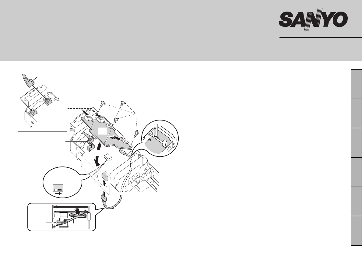
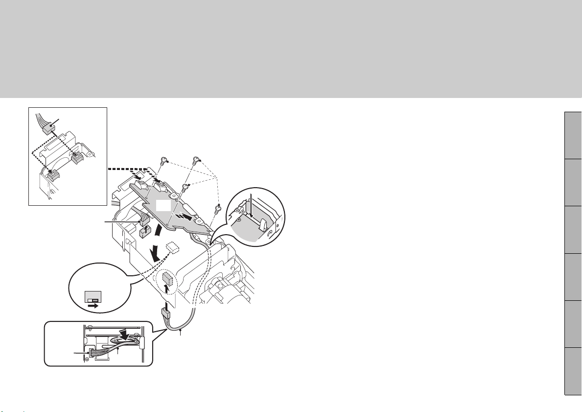
(*): This option board can output video signals through a UTP (Unshield Twist Pair)
cable. Use cable that is equivalent to or higher than LAN cable Category 5.
(C)
Remove the camera cover and then dismount the
1
camera unit.
• Please refer to the Installation Manual supplied with the
camera.
Remove the pin connector cable (A).
2
Passing the pin connector cable (C) on the option
3
board (B) through the gap of the circuit board,
connect it to the CN407 terminal on the bottom
side.
• Form the cable on the bottom side so that it doesn’t sag.
Diagonally inserting the option board, attach in
4
the direction of Arrow 1 and affix with the
supplied screws (D).
Connect the pin connector cable (A) that was
5
removed in 2 to the option board (B).
• When using a coaxial cable : Connect to CN604 (white)
• When using a UTP* cable : Connect to CN605 (red)
Turn the S4003 COM switch on the bottom side of
6
the circuit board to “Y”.
Connect the system devices (see page 4).
7
Following installation, configure the
8
communication settings (next page).
English Deutsch Français Español
中文简体
日本語
Page 2
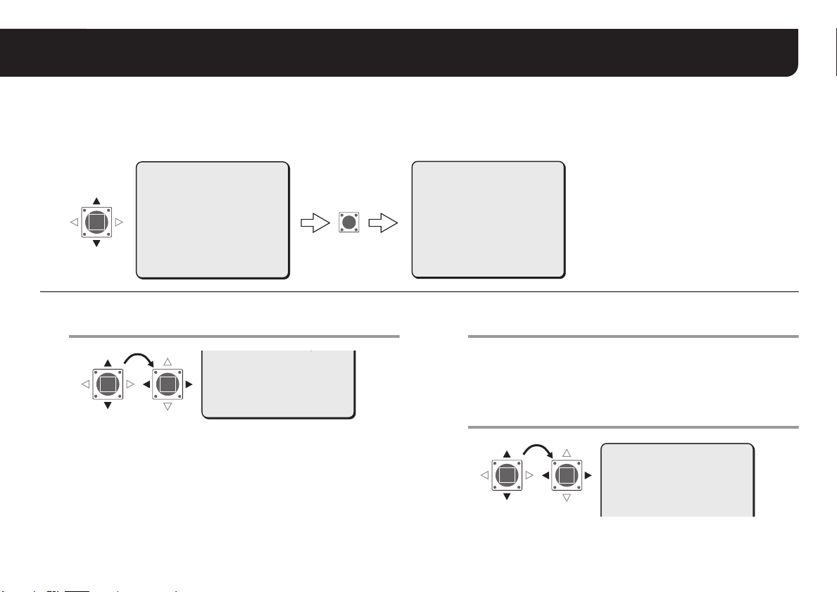
Configuring the Communication Settings
SET
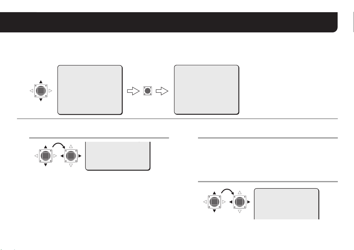
For you to be able to control this camera using the control device (such as system controller or camera control unit) you have
connected, you need to configure the communication settings through the menu screen. You may also output the alarm
signals to a communication line.
• For accessing the Main menu, see pages 5 - 7 on the INSTRUCTION MANUAL supplied with the camera.
SYNC
BLC
IRIS
WHITE BALANCE
AGC GAIN
GAMMA
SHUTTER
APERTURE
DAY/NIGHT
·OPTION
·OPTION
(SET)
Select “CONTROL” and specify the protocol for
1
PRESET
MENU
INT
OFF
SET y
ATW
NORM
0.45
60
HIGH
AUTO y
SET y
OFF
END
controlling the camera.
ALARM
LANGUAGE
·CONTROL
ADDRESS
ALARM LINE OUT
PRESET
MENU
·CONTROL
COAX : Coaxial superposition (SANYO: using coaxial cable)
• SSP, Hi-speed SSP and PELCO-C are supported.
Switching among the three is automatic.
485S : RS-485 (SANYO)
• Both SSP and Hi-speed SSP are supported. Switching
between the two is automatic.
485P : RS-485 (PELCO-D)
SET y
SET y
COAX y
1
OFF
OFF
BACK
2
SET
OPTION
·TITLE
PRIVACY MASK
PASSWORD
ALARM
LANGUAGE
CONTROL
ADDRESS
ALARM LINE OUT
PRESET
MENU
For advanced settings (485S or 485P), press the
2
SET button.
RThe “CONTROL SETTING” screen appears.
• Advance to step 5 if you have selected “COAX”.
Select “BAUD RATE” and specify the
3
communication speed.
·BAUD RATE
• Select from: 19200, 9600, 4800, 2400
OFF
SET y
SET y
SET y
SET y
COAX y
1
OFF
OFF
BACK
CONTROL SETTING
·BAUD RATE
TERMINATE
19200
OFF
Page 3
Configuring the Communication Settings
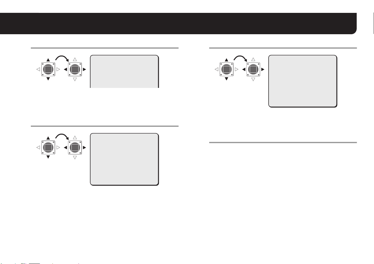
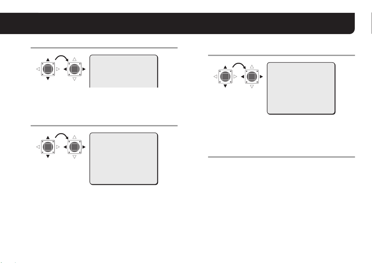
Set “TERMINATE” to “ON” or “OFF”.
4
CONTROL SETTING
BAUD RATE
·TERMINATE
19200
ON
·TERMINATE
ON : Camera is the cabling termination
OFF : No termination
Select “ADDRESS” and specify an address for
5
the camera (0 - 127).
OPTION
·ADDRESS
TITLE
PRIVACY MASK
PASSWORD
ALARM
LANGUAGE
CONTROL
·ADDRESS
ALARM LINE OUT
PRESET
MENU
OFF
SET y
SET y
SET y
SET y
COAX y
1
OFF
OFF
BACK
Set “ALARM LINE OUT” to “ON” or “OFF”.
6
OPTION
·
ALARM LINE OUT
TITLE
PRIVACY MASK
PASSWORD
ALARM
LANGUAGE
CONTROL
ADDRESS
·ALARM LINE OUT
PRESET
MENU
OFF
SET y
SET y
SET y
SET y
COAX y
1
ON
OFF
BACK
ON : Output alarm signals to communication line
OFF : No output
Set “MENU” to “END” and press the SET button.
7
RCloses the settings screen and returns to the normal monitoring
screen.
• If you want to return to the previous screen, select “BACK” and
press the SET button.
3
Page 4
■ Screen Sequence
SYNC
BLC
IRIS
WHITE BALANCE
AGC GAIN
GAMMA
SHUTTER
APERTURE
DAY/NIGHT
·OPTION
PRESET
MENU
INT
OFF
SET y
ATW
NORM
0.45
60
HIGH
AUTO y
SET y
OFF
END
OPTION
·TITLE
PRIVACY MASK
PASSWORD
ALARM
LANGUAGE
CONTROL
ADDRESS
ALARM LINE OUT
PRESET
MENU
OFF
SET y
SET y
SET y
SET y
COAX y
1
OFF
OFF
BACK
485S
485P
COAX
0 – 127
OFF/ON
CONTROL SETTING
·BAUD RATE
TERMINATE
MENU
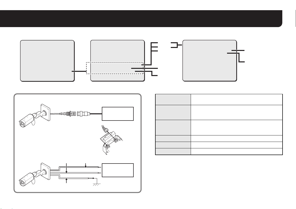
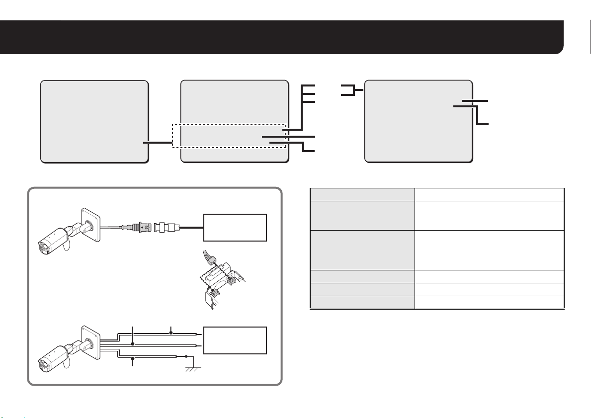
■ Connections ■ Specifications
■ When using coaxial cable
(*)
BNC type
(*): This option board can output video signals
through a UTP (Unshield Twist Pair) cable.
■ When using RS-485
RS485 (B):
Orange/Black
Brown
RS485 (A):
Gray
System device
(White: Coaxial)
(Red: UTP*)
System device
Communication
protocol
Video out
Power
consumption
Power source Supplied from main unit
Weight (approx.) 22.5 g (0.8 oz)
Accessory Screw x4
Appearance and specifications are subject to change without prior notice
or obligations.
19200
OFF
19200/9600/
4800/2400
OFF/ON
BACK
RS-485 / Coaxial control
Coaxial cable / UTP* cable
(*): Use cable that is equivalent to or higher than LAN
cable Category 5.
6.0 W (when installed on the main unit)
Max. 13.0 W with heater turned on (option board:
VA-50H)
4
Page 5
BEDIENUNGSANLEITUNG
Optionskarte (Kommunikation)
Zu dieser Anleitung
Lesen Sie bitte diese Anleitung vor der Installation und Verwendung dieser Einheit sorgfältig durch und
befolgen Sie die Anweisungen für den richtigen Gebrauch.
Entfernen Sie die Kameraabdeckung und nehmen Sie
(A)
(Weiß:
Koaxial)
(Rot: UTP*)
2
5
(A)
6
YN
S4003
COM
4
(D)
(B)
1
1
die Kameraeinheit ab.
• Siehe die Installationsanleitung der Kamera für weitere
Einzelheiten.
Ziehen Sie das Steckerkabel (A) ab.
2
Führen Sie das Steckerkabel (C) der Optionskarte (B)
3
durch den Spalt der Schaltplatine und schließen Sie es
am Anschluss CN407 auf der Unterseite an.
• Ordnen Sie das Kabel an der Unterseite so an, dass es nicht
durchhängt.
Die Optionskarte diagonal einführen, in Richtung des
4
Pfeils 1 anbringen und mit den beigefügten
Schrauben (D) befestigen.
Schließen Sie das (zuvor in Schritt 2 abgezogene)
5
Steckerkabel (A) an die Optionskarte (B) an.
• Bei Verwendung eines Koaxialkabels:
• Bei Verwendung eines UTP*-Kabels:
3
Stellen Sie den S4003 COM-Schalter auf der Unterseite
6
(C)
CN407
(*): Diese Optionskarte kann das Videosignal über ein UTP-Kabel ausgeben
(Unshield Twist Pair = Nicht abgeschirmtes verdrilltes Leiterpaar). Verwenden
Sie ein LAN-Kabel, das der Kategorie 5 oder höher entspricht.
(C)
der Schaltplatine auf „Y“.
Schließen Sie die Systemgeräte an (siehe Seite 4).
7
Nach erfolgter Installation nehmen Sie die
8
Kommunikationseinstellungen vor (siehe nächste
Seite).
VA-20ST
An CN604 (weiß) anschließen
An CN605 (rot) anschließen
English Deutsch Français Español
中文简体
日本語
1
Page 6
Kommunikationseinstellungen vornehmen
EINST
Um diese Kamera mit dem angeschlossenen Steuergerät (z.B. Systemsteuergerät oder Kamerasteuergerät) bedienen zu
können, müssen Sie zuvor die Kommunikationseinstellungen über den Menübildschirm konfigurieren. Sie können auch die
Alarmsignale auf eine Kommunikationsleitung ausgeben.
• Zum Aufrufen des Hauptmenüs siehe Seite 5 - 7 in der BEDIENUNGSANLEITUNG der Kamera.
OPTION
·BEZEICHNUNG
PRIV.MASK.
KENNWORT
ALARM
SPRACHE
STEUERUNG
ADRESSE
LEITUNG AUSG.
VOREINST.
MENUE
AUS
EINSTy
EINSTy
EINSTy
EINSTy
COAX y
1
AUS
AUS
ZURUECK
·OPTION
(EINST)
SYNC
BLC
IRIS
WEISSABGLEICH
AGC VERSTAERK.
GAMMA
VERSCHLUSSZEIT
BLENDE
TAG/NACHT
·OPTION
VOREINST.
MENUE
INT
AUS
EINSTy
ATW
NORM
0.45
60
HOCH
AUTO y
EINSTy
AUS
ENDE
SET
Wählen sie „STEUERUNG“ aus und geben Sie
1
das Protokoll für die Steuerung der Kamera an.
ALARM
SPRACHE
·STEUERUNG
ADRESSE
LEITUNG AUSG.
VOREINST.
MENUE
·CONTROL
COAX : Koaxiale Überlagerung (SANYO: Verwendung eines
Koaxialkabels)
• Es werden SSP, Hi-speed SSP und PELCO-C
unterstützt. Die Umschaltung zwischen den drei erfolgt
automatisch.
485S : RS-485 (SANYO)
• Es wird sowohl SSP als auch Hi-speed SSP unterstützt.
Die Umschaltung zwischen den beiden erfolgt
automatisch.
485P : RS-485 (PELCO-D)
EINSTy
EINSTy
COAX y
1
AUS
AUS
ZURUECK
2
Drücken Sie zum Aufrufen der erweiterten
2
Einstellungen (485S oder 485P) die SET-Taste.
RDer Bildschirm „STEUERUNG EINST.“ wird angezeigt.
• Gehen Sie weiter zu Schritt 5, falls Sie „COAX“ gewählt
haben.
Wählen Sie „BAUDRATE“ und geben Sie die
3
Übertragungsgeschwindigkeit an.
STEUERUNG EINST.
·BAUDRATE
BEENDEN
·BAUDRATE
• Wählen Sie aus: 19200, 9600, 4800, 2400
19200
AUS
Page 7
Kommunikationseinstellungen vornehmen
Stellen Sie „BEENDEN“ auf „EIN“ oder „AUS“ ein.
4
STEUERUNG EINST.
BAUDRATE
·BEENDEN
19200
EIN
·BEENDEN
EIN : Die Kamera ist der Abschluss
AUS : Kein Abschluss
Wählen Sie „ADRESSE“ und geben Sie eine
5
Adresse für die Kamera an (0 - 127).
OPTION
·ADRESSE
BEZEICHNUNG
PRIV.MASK.
KENNWORT
ALARM
SPRACHE
STEUERUNG
·ADRESSE
LEITUNG AUSG.
VOREINST.
MENUE
AUS
EINSTy
EINSTy
EINSTy
EINSTy
COAX y
1
AUS
AUS
ZURUECK
Stellen Sie „LEITUNG AUSG.“ auf „EIN“ oder
6
„AUS“ ein.
OPTION
BEZEICHNUNG
PRIV.MASK.
KENNWORT
ALARM
·
LEITUNG AUSG.
SPRACHE
STEUERUNG
ADRESSE
·LEITUNG AUSG.
VOREINST.
MENUE
EIN : Alarmsignalausgabe auf Kommunikationsleitung
AUS : Keine Ausgabe
„MENUE“ auf „ENDE“ einstellen und die
7
SET-Taste drücken.
RSchließt den Einstellbildschirm und schaltet zum normalen
Monitorbildschirm zurück.
• Um auf den vorhergehenden Bildschirm zurückzuschalten,
stellen Sie „ZURUECK“ ein und drücken Sie die SET-Taste.
AUS
EINSTy
EINSTy
EINSTy
EINSTy
COAX y
1
EIN
AUS
ZURUECK
3
Page 8
■ Bildschirmfolge
SYNC
BLC
IRIS
WEISSABGLEICH
AGC VERSTAERK.
GAMMA
VERSCHLUSSZEIT
BLENDE
TAG/NACHT
·OPTION
VOREINST.
MENUE
INT
AUS
EINSTy
ATW
NORM
0.45
60
HOCH
AUTO y
EINSTy
AUS
ENDE
OPTION
·BEZEICHNUNG
PRIV.MASK.
KENNWORT
ALARM
SPRACHE
STEUERUNG
ADRESSE
LEITUNG AUSG.
VOREINST.
MENUE
AUS
EINSTy
EINSTy
EINSTy
EINSTy
COAX y
1
AUS
AUS
ZURUECK
485S
485P
COAX
0 – 127
AUS/EIN
STEUERUNG EINST.
·BAUDRATE
BEENDEN
MENUE
■ Anschlüsse ■ Technische Daten
■ Bei Verwendung eines Koaxialkabels
(*)
BNC
(*): Diese Optionskarte kann das Videosignal über
ein UTP-Kabel ausgeben (Unshielded Twisted
Pair = Nicht abgeschirmtes verdrilltes
Leiterpaar).
■ Bei Verwendung von RS-485
RS485 (B):
Orange/Schwarz
RS485 (A):
Grau
Braun
Systemgerät
(Weiß: Koaxial)
(Rot: UTP*)
Systemgerät
Kommunikationsprotokoll RS-485 / Koaxial
Video-Ausgang
Leistungsaufnahme
Stromquelle Versorgung durch das Hauptgerät
Gewicht (ungefähr) 22,5 g (0,8 oz)
Zubehör Schraube x4
Änderungen des Aussehens und der technischen Daten des Produktes
ohne Vorankündigung und Verpflichtung bleiben vorbehalten.
19200
AUS
19200/9600/
4800/2400
AUS/EIN
ZURUECK
Koaxialkabel / UTP*-Kabel
(*): Verwenden Sie ein LAN-Kabel, das der
Kategorie 5 oder höher entspricht.
6,0 W (bei Installation auf dem
Hauptgerät)
Max. 13,0 W bei eingeschalteter
Heizung (Optionskarte: VA-50H)
4
Page 9

MANUEL D’INSTRUCTIONS
Carte optionnelle (Communications)
À propos de ce manuel
Avant d’installer et d’utiliser cet appareil, veuillez lire avec attention le présent manuel et respectez toujours
les instructions fournies pour sa bonne utilisation.
Otez la protection de la caméra, puis démontez le
(A)
5
(Blanc:
Coaxial)
(Rouge: UTP*)
2
(B)
(A)
1
4
(D)
6
YN
S4003
COM
3
(C)
CN407
(*) :Cette carte optionnelle peut transmettre des signaux vidéo via un câble UTP
(Unshield Twist Pair - paire torsadée non blindée). Utilisez un câble équivalent
ou supérieur à un câble LAN de catégorie 5.
(C)
1
groupe caméra.
• Veuillez vous reporter au Manuel d’installation fourni avec la
caméra.
Enlevez le câble avec connecteur à broches (A).
2
En faisant passer le câble avec connecteur à
3
broches (C) de la carte optionnelle (B) à travers
l’espace de la carte de circuit imprimé, branchez-le
sur la borne CN407 située côté inférieur.
• Placez le câble côté inférieur de façon à ce qu’il ne pende pas.
Insérez la carte optionnelle diagonalement,
4
appuyez dans la direction de la flèche 1 et
fixez-la avec les vis (D) fournies.
Rebranchez le câble avec connecteur à broches
5
(A), précédemment enlevé au point 2, sur la
carte optionnelle (B).
• Si vous utilisez un câble coaxial : branchez-le sur CN604 (blanc)
• Si vous utilisez un câble UTP* : branchez-le sur CN605 (rouge)
Réglez l’interrupteur S4003 COM situé sur le côté
6
inférieur de la carte de circuit imprimé sur « Y ».
Branchez les dispositifs de système (voir page 4).
7
Après l’installation, configurez les réglages de
8
communication (page suivante).
VA-20ST
English Deutsch Français Español
中文简体
日本語
1
Page 10

Configuration des réglages de communication
/SS
REG y
Pour que vous puissiez commander la caméra via le dispositif de commande (tel qu’un contrôleur de système ou une
télécommande pour caméra) que vous avez branché, vous devez configurer les réglages de communication par l’intermédiaire
de l’écran de menu. Vous pouvez aussi transmettre les signaux d’alarme sur une ligne de communication.
• Pour accéder au menu principal, reportez-vous aux pages 5 - 7 du MANUEL D’INSTRUCTIONS fourni avec la caméra.
1
2
·OPTION
(REG)
SYNC
BLC
IRIS
EQUIL BLANC
GAIN CAG
GAMMA
VIT OBTURATEUR
OUVERTURE
JOUR/NUIT
·OPTION
PREREGLAGE
MENU
INT
ARR
REG y
ATW
NORM
0.45
60
HAUT
AUTO y
REG y
ARR
FIN
SET
Sélectionnez « COMMANDE » et spécifiez le
protocole de commande de la caméra.
ALARME
LANGUE
·COMMANDE
ADRESSE
SORTIE LIGNE
PREREGLAGE
·COMMANDE
MENU
COAX : Superposition coaxiale (SANYO : via un câble coaxial)
• Les protocoles SSP, SSP grande vitesse et PELCO-C
sont pris en charge. La commutation entre les trois est
automatique.
485S : RS-485 (SANYO)
• Les protocoles SSP et SSP grande vitesse sont pris en
charge. La commutation entre les deux est
automatique.
485P : RS-485 (PELCO-D)
REG y
REG y
COAX y
1
ARR
ARR
RETOUR
OPTION
·TITRE
MASQUE
M/PASSE
ALARME
LANGUE
COMMANDE
ADRESSE
SORTIE LIGNE
PREREGLAGE
MENU
Pour des réglages avancés (485S ou 485P),
2
appuyez sur le bouton SET.
RL’écran « REGLAGE COMMANDE » s’affiche.
• Passez au point 5 si vous avez sélectionné « COAX ».
Sélectionnez « VIT. DE TRANS. » et spécifiez la
3
vitesse de communication.
·VIT.DE TRANS.
• Sélectionnez une des
valeurs suivantes : 19200, 9600, 4800, 2400
ARR
REG y
REG y
REG y
REG y
COAX y
1
ARR
ARR
RETOUR
REGLAGE COMMANDE
·VIT.DE TRANS.
TERMINAISON
19200
ARR
Page 11

Configuration des réglages de communication
Réglez « TERMINAISON » sur « MAR » ou
4
« ARR ».
REGLAGE COMMANDE
VIT.DE TRANS.
·TERMINAISON
·TERMINAISON
MAR : La caméra est la terminaison de câblage
ARR : Pas de terminaison
Sélectionnez « ADRESSE » et spécifiez une
5
adresse pour la caméra (0 - 127).
OPTION
TITRE
MASQUE
M/PASSE
ALARME
·ADRESSE
LANGUE
COMMANDE
·ADRESSE
SORTIE LIGNE
PREREGLAGE
MENU
19200
MAR
ARR
REG y
REG y
REG y
REG y
COAX y
1
ARR
ARR
RETOUR
Réglez « SORTIE LIGNE » sur « MAR » ou
6
« ARR ».
OPTION
·
SORTIE LIGNE
TITRE
MASQUE
M/PASSE
ALARME
LANGUE
COMMANDE
ADRESSE
·SORTIE LIGNE
PREREGLAGE
MENU
ARR
REG y
REG y
REG y
REG y
COAX y
1
MAR
ARR
RETOUR
MAR : Sortie des signaux d’alarme sur une ligne de
communication
ARR : Pas de sortie
Sélectionnez « FIN » dans « MENU » et appuyez
7
sur le bouton SET.
RL’écran de réglage se ferme et l’écran normal de contrôle
réapparaît.
• Pour retourner à l’écran précédent, sélectionnez « RETOUR »
et appuyez sur le bouton SET.
3
Page 12

■ Séquence des écrans
SYNC
BLC
IRIS
EQUIL BLANC
GAIN CAG
GAMMA
VIT OBTURATEUR
OUVERTURE
JOUR/NUIT
·OPTION
PREREGLAGE
MENU
INT
ARR
REG y
ATW
NORM
0.45
60
HAUT
AUTO y
REG y
ARR
FIN
OPTION
·TITRE
MASQUE
M/PASSE
ALARME
LANGUE
COMMANDE
ADRESSE
SORTIE LIGNE
PREREGLAGE
MENU
ARR
REG y
REG y
REG y
REG y
COAX y
1
ARR
ARR
RETOUR
485S
485P
COAX
0 – 127
ARR/MAR
REGLAGE COMMANDE
·VIT.DE TRANS.
TERMINAISON
MENU
■ Branchements ■ Spécifications
■ Avec un câble coaxial
(*)
Type BNC
(*) : Cette carte optionnelle peut transmettre des
signaux vidéo via un câble UTP (Unshield Twist
Pair - paire torsadée non blindée).
■ Avec RS-485
RS485 (B):
Orange/Noir
Marron
RS485 (A):
Gris
Dispositif de
système
(Blanc: Coaxial)
(Rouge: UTP*)
Dispositif de
système
Protocole de
communication
Sortie vidéo
Consommation
d’énergie
Source
d’alimentation
Poids (environ) 22,5 g (0,8 oz)
Accessoire Vis x4
Les caractéristiques et les spécifications peuvent être modifiées à tout
moment et sans préavis.
19200
ARR
19200/9600/
4800/2400
ARR/MAR
RETOUR
Commande RS-485 / Coaxial
Câble coaxial / Câble UTP*
(*) : Utilisez un câble équivalent ou supérieur à un câble
LAN de catégorie 5.
6,0 W (quand installée sur l’unité principale)
13,0 W maxi avec dispositif de chauffage activé
(Carte en option: VA-50H)
Fournie depuis l’unité principale
4
Page 13

MANUAL DE INSTRUCCIONES
Placa opcional (comunicaciones)
Acerca de este manual
Antes de instalar y usar esta unidad lea este manual y siga las instrucciones del mismo para asegurar
un uso correcto.
Quitar la carcasa de la cámara y a continuación
(A)
5
(Blanco:
Coaxial)
(Rojo: UTP*)
2
(B)
(A)
1
4
(D)
6
YN
S4003
COM
3
(C)
CN407
(*): Esta placa opcional puede producir señales de vídeo a través de un cable UTP
(par trenzado sin blindaje). Usar un cable equivalente o superior al cable LAN
categoría 5.
(C)
1
desmontar la unidad de la cámara.
• Consultar el Manual de instalación facilitado con la cámara.
Extraer el cable del conector de pines (A).
2
Pasando el cable del conector de pines (C) de la
3
placa opcional (B) a través de la abertura de la
placa de circuito, conectarlo al terminal CN407
de la parte inferior.
• Formar el cable del lado inferior de modo que no se combe.
Insertando diagonalmente la placa opcional,
4
montar en la dirección de la flecha 1 y fijar con
los tornillos que se incluyen (D).
Conectar el cable del conector de pines (A) que
5
se extrajo en el punto 2 en la placa opcional (B).
• Si se usa un cable coaxial : conectar en CN604 (blanco)
• Si se usa un cable UTP* : conectar en CN605 (rojo)
Colocar el conmutador S4003 COM de la parte
6
inferior de la placa de circuito en “Y”.
Conectar los dispositivos del sistema
7
(ver la página 4).
Después de la instalación, configurar los ajustes
8
de comunicación (página siguiente).
VA-20ST
English Deutsch Français Español
中文简体
日本語
1
Page 14

Configuración de los ajustes de comunicación
AJU
Para poder controlar esta cámara utilizando el dispositivo de control (como un controlador de sistema o una unidad de control
de cámara) que se haya conectado, es necesario configurar los ajustes de comunicación mediante la pantalla de menú.
También se pueden enviar las señales de alarma a una línea de comunicación.
• Para entrar en el menú principal, consultar las páginas 5 - 7 del MANUAL DE INSTRUCCIONES suministrado con la cámara.
SINC
BLC
IRIS
BALANCE BLANCO
GANANCIA AGC
GAMMA
VELO OBTURADOR
APERTURA
DIA/NOCHE
·OPCION
·OPCION
(AJU)
Seleccionar “CONTROL” y especificar el
1
PREAJUSTES
MENU
INT
OFF
AJU y
ATW
NORM
0.45
60
ALTA
AUTO y
AJU y
OFF
FIN
protocolo para el control de cámara.
ALARMA
IDIOMA
·CONTROL
DIRECCION
SAL.LIN.ALARMAS
PREAJUSTES
MENU
·CONTROL
COAX : Convolución coaxial (SANYO: usando el cable coaxial)
• Se admiten SSP, SSP Alta velocidad y PELCO-C.
La conmutación entre los tres es automática.
485S : RS-485 (SANYO)
• Se admite tanto SSP como SSP Alta velocidad.
La conmutación entre los dos es automática.
485P : RS-485 (PELCO-D)
AJU y
AJU y
COAX y
1
OFF
OFF
ATRAS
2
SET
OPCION
·TITULO
MASCARA PRIV
CONTRASENA
ALARMA
IDIOMA
CONTROL
DIRECCION
SAL.LIN.ALARMAS
PREAJUSTES
MENU
Para los ajustes avanzados (485S o 485P), pulsar
2
el botón SET.
RSe visualiza la pantalla “AJUSTE CONTROL”.
• Pasar al paso 5 si se ha seleccionado “COAX”.
Seleccionar “TASA DE BAUDIOS" y especificar la
3
velocidad de comunicación.
·
TASA DE BAUDIOS
• Seleccionar entre: 19200, 9600, 4800, 2400
OFF
AJU y
AJU y
AJU y
AJU y
COAX y
1
OFF
OFF
ATRAS
AJUSTE CONTROL
·TASA DE BAUDIOS
TERMINAL
19200
OFF
Page 15

Configuración de los ajustes de comunicación
Ajustar “TERMINAL” en “ON” u “OFF”.
4
AJUSTE CONTROL
TASA DE BAUDIOS
·TERMINAL
·TERMINAL
ON : La cámara es la terminación de cables
OFF : Ninguna terminación
Seleccionar “DIRECCION” y especificar una
5
dirección para la cámara (0 - 127).
OPCION
TITULO
MASCARA PRIV
CONTRASENA
ALARMA
·DIRECCION
IDIOMA
CONTROL
·DIRECCION
SAL.LIN.ALARMAS
PREAJUSTES
MENU
19200
ON
OFF
AJU y
AJU y
AJU y
AJU y
COAX y
1
OFF
OFF
ATRAS
Ajustar “SAL. LIN. ALARMAS” en “ON” u “OFF”.
6
OPCION
·
SAL.LIN.ALARMAS
TITULO
MASCARA PRIV
CONTRASENA
ALARMA
IDIOMA
CONTROL
DIRECCION
·SAL.LIN.ALARMAS
PREAJUSTES
MENU
OFF
AJU y
AJU y
AJU y
AJU y
COAX y
1
ON
OFF
ATRAS
ON : Salida de señales de alarma a la línea de comunicación
OFF : Ninguna salida
Ajustar “MENU” en “FIN” y pulsar el botón SET.
7
RSe cierra la pantalla de ajustes y se vuelve a la pantalla de
monitorización normal.
• Si se desea volver a la pantalla anterior, seleccionar “ATRAS" y
pulsar el botón SET.
3
Page 16

■ Secuencia de pantallas
SINC
BLC
IRIS
BALANCE BLANCO
GANANCIA AGC
GAMMA
VELO OBTURADOR
APERTURA
DIA/NOCHE
·OPCION
PREAJUSTES
MENU
INT
OFF
AJU y
ATW
NORM
0.45
60
ALTA
AUTO y
AJU y
OFF
FIN
OPCION
·TITULO
MASCARA PRIV
CONTRASENA
ALARMA
IDIOMA
CONTROL
DIRECCION
SAL.LIN.ALARMAS
PREAJUSTES
MENU
OFF
AJU y
AJU y
AJU y
AJU y
COAX y
1
OFF
OFF
ATRAS
485S
485P
COAX
0 – 127
OFF/ON
AJUSTE CONTROL
·TASA DE BAUDIOS
TERMINAL
MENU
■ Conexiones ■ Especificaciones
■ Si se usa un cable coaxial
(*)
Tipo BNC
(*): Esta placa opcional puede producir señales de
vídeo a través de un cable UTP (par trenzado sin
blindaje).
■ Si se usa RS-485
RS485 (B):
Anaranjado/Negro
Marrón
RS485 (A):
Gris
Dispositivo de
sistema
(Blanco:
Coaxial
(Rojo: UTP*)
Dispositivo de
sistema
)
Protocolo de
comunicación
RS-485 / Control coaxial
Cable coaxial / Cable UTP*
Salida de vídeo
Consumo
eléctrico
Fuente de
alimentación
(*): Usar un cable equivalente o superior al cable LAN
6,0 W (si se instala en la unidad principal)
Máx. 13,0 W con el calentador encendido (placa
opcional: VA-50H)
Suministrada por la unidad principal
Peso (aprox.) 22,5 g (0,8 onzas)
Accesorio Tornillo x4
El aspecto y las características técnicas pueden sufrir variaciones sin
previo aviso u obligación.
categoría 5.
19200
OFF
ATRAS
19200/9600/
4800/2400
OFF/ON
4
Page 17

说明手册
选项板 (通信)
关于本手册
在安装和使用此装置之前,请阅读此手册,并务必遵守其中的说明,以正确使用此装置。
VA-20ST
(A)
5
(白色 :
同轴电缆)
(红色 : UTP*)
2
(B)
(A)
1
4
(D)
6
YN
S4003
COM
3
(C)
CN407
(*): 该选项板可以通过 UTP (非屏蔽双绞线)输出视频信号。应使用等效于或优于
Category 5 LAN 的电缆。
(C)
取下摄像机罩,然后拆下摄像机装置。
1
• 请参阅摄像机随附的安装手册。
取下针式接头电缆 (A)。
2
将选项板 (B)上的针式接头电缆 (C)穿过电路板
3
的缝隙,将它连接到底部端子CN407上。
• 将电缆沿着底部成形放置以避免其下垂。
按对角线方向插入选项板,沿着箭头1的方向安装,
4
然后用随附的螺钉 (D)将其固定。
将在步骤2中取下的针式接头电缆 (A)连接到选项
5
板(B)。
• 使用同轴电缆时 :连接到 CN604 (白色)
• 使用 UTP* 电缆时 :连接到 CN605 (红色)
将电路板底部上的S4003 COM开关转到 “Y”。
6
连接系统设备 (请参见第4页)。
7
安装之后,配置通信设置 (请参见下一页)。
8
English Deutsch Français Español
中文简体
日本語
1
Page 18

配置通信设置
SET
为了使您能够使用已连接的控制设备 (如系统控制器或摄像机控制器)控制此摄像机,您需要通过菜单屏幕配置通信设置。 您还可以将
报警信号输出到通信线路。
• 有关访问主菜单的信息,请参见摄像机随附的说明手册的第 5 至 7 页。
SYNC
BLC
IRIS
WHITE BALANCE
AGC GAIN
GAMMA
SHUTTER
APERTURE
DAY/NIGHT
·OPTION
·OPTION
(SET)
选择 “CONTROL”指定用于控制摄像机的协议。
1
PRESET
MENU
·CONTROL
INT
OFF
SET y
ATW
NORM
0.45
60
HIGH
AUTO y
SET y
OFF
END
ALARM
LANGUAGE
·CONTROL
ADDRESS
ALARM LINE OUT
PRESET
MENU
SET y
SET y
COAX y
1
OFF
OFF
BACK
COAX:同轴卷绕 (SANYO:使用同轴电缆)
• 同时支持 SSP, 高速 SSP 和 PELCO-C。三者之间的切换自
动进行。
485S :RS-485 (SANYO)
• 同时支持 SSP 和高速 SSP。 两者之间的切换自动进行。
485P :RS-485 (PELCO-D)
SET
OPTION
·TITLE
PRIVACY MASK
PASSWORD
ALARM
LANGUAGE
CONTROL
ADDRESS
ALARM LINE OUT
PRESET
MENU
要进行高级设置 (485S或485P),请按SET按钮。
2
R显示 “CONTROL SETTING”屏幕。
• 如果您已经选择 “COAX”,请前进到步骤 5 。
选择 “BAUD RATE”并指定通信速度。
3
·BAUD RATE
• 选择项:
OFF
SET y
SET y
SET y
SET y
COAX y
1
OFF
OFF
BACK
19200, 9600, 4800, 2400
CONTROL SETTING
·BAUD RATE
TERMINATE
19200
OFF
2
Page 19

配置通信设置
将“TERMINATE”设置为 “ON”或 “OFF”。
4
CONTROL SETTING
BAUD RATE
·TERMINATE
·TERMINATE
ON :摄像机为电缆终端
OFF :无终端
5
选择 “
ADDRESS
·ADDRESS
”为摄像机指定一个地址
OPTION
TITLE
PRIVACY MASK
PASSWORD
ALARM
LANGUAGE
CONTROL
·ADDRESS
ALARM LINE OUT
PRESET
MENU
19200
ON
(0 - 127)
OFF
SET y
SET y
SET y
SET y
COAX y
1
OFF
OFF
BACK
。
将“
6
ALARM LINE OUT
·
ALARM LINE OUT
”设置为 “ON”或 “
OPTION
TITLE
PRIVACY MASK
PASSWORD
ALARM
LANGUAGE
CONTROL
ADDRESS
·ALARM LINE OUT
PRESET
MENU
OFF
SET y
SET y
SET y
SET y
COAX y
1
ON
OFF
BACK
ON :将报警信号输出到通信线路
OFF :无输出
将“MENU”设置为 “END”,然后按SET按钮。
7
R关闭设置屏幕,返回正常监控屏幕。
• 如果希望返回前一屏幕,请选择 “BACK”然后按 SET 按钮。
OFF”。
3
Page 20

■ 屏幕序列
SYNC
BLC
IRIS
WHITE BALANCE
AGC GAIN
GAMMA
SHUTTER
APERTURE
DAY/NIGHT
·OPTION
PRESET
MENU
INT
OFF
SET y
ATW
NORM
0.45
60
HIGH
AUTO y
SET y
OFF
END
OPTION
·TITLE
PRIVACY MASK
PASSWORD
ALARM
LANGUAGE
CONTROL
ADDRESS
ALARM LINE OUT
PRESET
MENU
OFF
SET y
SET y
SET y
SET y
COAX y
1
OFF
OFF
BACK
485S
485P
COAX
0 – 127
OFF/ON
■ 连接 ■ 规格
■ 当使用同轴电缆时
(*)
BNC 类型
(*): 该选项板可以通过 UTP (非屏蔽双绞线)输出
视频信号。
■ 当使用 RS-485 时
RS485 (B):
橙色 / 黑色
RS485 (A):
灰色
棕色
系统设备
(白色 : 同轴电缆)
(红色 : UTP*)
系统设备
公用
通信协议 RS-485 / 同轴控制
视频输出
功耗
电源 由主机提供
重量(大约
附件 螺钉 x4
产品外观和规格如有变更,恕不另行通告。
CONTROL SETTING
·BAUD RATE
TERMINATE
MENU
19200
OFF
BACK
同轴电缆 / UTP*电缆
(*): 应使用等效于或优于 Category 5 LAN 的电缆。
6.0 W (当安装在主机上时)
最大值13.0 W 打开加热器 (选项板:VA - 5 0 H )
22.5 g (0.8 oz)
)
19200/9600/
4800/2400
OFF/ON
4
Page 21

取扱説明書
オプションボード(通信)
本書について
ご使用前にこの取扱説明書をよくお読みのうえ、正しくお使いください。
(A)
5
(白:同軸)
(赤:UTP*)
2
(B)
(A)
1
4
(D)
6
YN
S4003
COM
3
(C)
CN407
(C)
VA-20ST
カメラカバーと本体を取りはずしてください。
1
• カメラ本体に付属の設置説明書をご参照ください。
コネクター(A)をはずす
2
オプションボード(B)のコネクター(C)をメイン
3
基板のすき間から通し下側CN407端子に接続する
• 下側に出ているケーブルは浮き上がらないように整形してく
ださい。
オプションボードを斜めに差し込みながら矢印1の
4
方向に装着し、付属のネジ(D)で固定する
2で取りはずしたコネクター(A)をオプション
5
ボード(B)に接続する
• 同軸ケーブルを使用する場合:CN604(白)
• UTP* ケーブルを使用する場合:CN605(赤)
メイン基板の下側S4003COMスイッチをY
6
にする
システム機器を接続する(裏表紙参照)
7
設置が完了したら、通信条件を設定する(次ページ)
8
English Deutsch Français Español
中文简体
日本語
(*): 本ボードは、UTP(UnshieldTwistPair)ケーブルでも映像信号を出力する
ことができます。LAN ケーブル Category5 相当以上をご使用ください。
1
Page 22

通信条件を設定する
SET
接続したシステム機器(システムコントローラーやカメラコントロールユニットなど)で本機をコントロールする場合、通信条件を
メニュー画面で設定してください。また、通信ラインへアラーム信号を出力することもできます。
• メインメニューへのアクセス方法は、カメラ本体に付属の INSTRUCTIONMANUAL5-7 ページをご参照ください。
SYNC
BLC
IRIS
WHITE BALANCE
AGC GAIN
GAMMA
SHUTTER
APERTURE
DAY/NIGHT
·OPTION
·OPTION
(SET)
CONTROLを選んで、カメラをコントロールす
1
PRESET
MENU
INT
OFF
SET y
ATW
NORM
0.45
60
HIGH
AUTO y
SET y
OFF
END
SET
るプロトコルを設定する
ALARM
LANGUAGE
·CONTROL
ADDRESS
ALARM LINE OUT
PRESET
MENU
·CONTROL
COAX : 同軸重畳(SANYO;同軸ケーブル使用 )
• SSP/Hi-speedSSP/PELCO-C の 3 種類に対応。
切換は自動。
485S : RS-485(SANYO)
• SSP/Hi-speedSSP の 2 種類に対応。切換は自動。
485P : RS-485(PELCO-D)
SET y
SET y
COAX y
1
OFF
OFF
BACK
OPTION
·TITLE
PRIVACY MASK
PASSWORD
ALARM
LANGUAGE
CONTROL
ADDRESS
ALARM LINE OUT
PRESET
MENU
詳細設定をする場合は、SETボタンを押す
2
RCONTROLSETTING画面になります。
• "COAX" に設定した場合は、ステップ 5 にすすんでください。
BAUDRATEを選んで、通信速度を設定する
3
·BAUD RATE
• 19200,9600,4800,2400
OFF
SET y
SET y
SET y
SET y
COAX y
1
OFF
OFF
BACK
CONTROL SETTING
·BAUD RATE
TERMINATE
19200
OFF
2
Page 23

通信条件を設定する
TERMINATEをONまたはOFFに設定
4
する
CONTROL SETTING
BAUD RATE
·TERMINATE
19200
ON
·TERMINATE
ON : 本機を配線の終端にする
OFF : 終端にしない
ADDRESSを選んで、カメラのアドレスを設定
5
する
OPTION
·ADDRESS
TITLE
PRIVACY MASK
PASSWORD
ALARM
LANGUAGE
CONTROL
·ADDRESS
ALARM LINE OUT
PRESET
MENU
OFF
SET y
SET y
SET y
SET y
COAX y
1
OFF
OFF
BACK
ALARMLINEOUTをONまたはOFF
6
に設定する
OPTION
·
ALARM LINE OUT
TITLE
PRIVACY MASK
PASSWORD
ALARM
LANGUAGE
CONTROL
ADDRESS
·ALARM LINE OUT
PRESET
MENU
OFF
SET y
SET y
SET y
SET y
COAX y
1
ON
OFF
BACK
ON : 通信ラインへ、アラーム信号を出力する
OFF : 出力しない
MENUをENDに設定してからSETボタン
7
を押す
R設定画面から抜けて通常のモニター画面になります。
• 前画面に戻りたいときは、BACKのまま SET ボタンを押し
てください。
3
Page 24

■ 設定画面一覧
/
SYNC
BLC
IRIS
WHITE BALANCE
AGC GAIN
GAMMA
SHUTTER
APERTURE
DAY/NIGHT
·OPTION
PRESET
MENU
INT
OFF
SET y
ATW
NORM
0.45
60
HIGH
AUTO y
SET y
OFF
END
■ 接続
■ 同軸ケーブルを使用する場合
(*)
システム機器
BNCタイプ
OPTION
·TITLE
PRIVACY MASK
PASSWORD
ALARM
LANGUAGE
CONTROL
ADDRESS
ALARM LINE OUT
PRESET
MENU
OFF
SET y
SET y
SET y
SET y
COAX y
1
OFF
OFF
BACK
485S
485P
COAX
0 – 127
OFF/ON
CONTROL SETTING
·BAUD RATE
TERMINATE
MENU
19200
OFF
BACK
■ 仕様
通信方式 RS-485/同軸制御
ビデオ出力
消費電力
電源 本体から給電
質量(約) 22.5g(0.8oz)
付属品 ネジ×4
外観および仕様は、お断りなしに変更する場合がありますのでご了承
ください。
Printed on recycled paper
Gedruckt auf Recyclingpapier
Imprimé sur du papier recyclé
1AC6P1P3056-L9EAY/WA (0306KP-SY)
同軸ケーブル/UTP*ケーブル
(*): LAN ケーブル Category5 相当以上をご使用ください。
6.0W(本体取付け時)
最大13.0W ヒーター ON時
(オプションボード:VA-50H)
Impreso en papel reciclado
使用再生纸印刷
この取扱説明書は、再生紙を使用しています
19200/9600
4800/2400
OFF/ON
(*): 本ボードは、UTP(UnshieldTwistPair)ケー
ブルでも映像信号を出力することができます。
■ RS-485 を使用する場合
RS485(B):
オレンジ/黒
RS485(A):
グレー
茶色
SANYO Electric Co., Ltd.
Printed in Japan
(白:同軸)
(赤:UTP*)
システム機器
 Loading...