

Page 1
BASIC SERVICE TECHNICAL
piw
INFORMATION
FILENO.
Siiio
Video Cassette Recorder
V95 IMECHANISM
PALSECAM NTSC
Contents
1. MAINTAINING AND CHECKING
--
--
L
THE MECHANISM
1-1. REGULARCHECKSAND
MAINTENANCE ITEMS ...................2
1-2. SERVICETOOLS ..............................3
2. AN OVERVIEW OF THE
MECHANISM
2-1. NAMES OF THE MAIN PARTS .......4
2-2. AN OVERVIEW OF THE
MECHANISM MODES .....................6
3. DIS-ASSEMBLING THE MAIN
PARTS OF THE MECHANISM
3-1. HOW TO MAKE THE MECHANISM
MOVE ...............................................8
3-2. MECHANISM UNIT .........................9
3-3. CASSETTEDRIVEMECHANISM ....9
3-4. CLEANERROLLER
ASSEMBLY .................................... 11
3-5. CYLINDER(DRUM) ........................12
3-6. FEHEAD AND ACE HEAD.............I4
3-7. CAPSTAN MOTOR ........................15
3-8. LOADING MOTOR ASSEMBLY
AND WORM GEARASSEMBLY ...16
3-9. PINCH ROLLERPRESSURE
MECHANISM .................................16
3-10. L GUIDE LEVERASSEMBLY AND
LOAD LEVERASSEMBLY .............18
3-11. BT LEVERASSEMBLY ..................18
3-12. REELDRIVEMECHANISM ............19
3-13. BRAKES .........................................20
3-14. GUIDES ..........................................22
3-15. WHEEL GEAR2, MAIN CAM AND
MODE SWITCH ..............................23
3-16. CRESCENTSLIDE ..........................24
3-17. S LOAD GEAR,T LOAD GEAR,
S LOAD LEVERASSEMBLY AND
T LOAD LEVERASSEMBLY ..........25
3-18. TAPE SENSORS, REELSENSOR
AND EPSW LEVER .......................26
4. MECHANISM CHECKS AND
ADJUSTMENTS
4-1. REELTABLETORQUE CHECK......27
4-2. ADJUSTING THE BT LEVER
ASSEMBLY POSITION AND
CHECKINGTHE BACKTENSION
TORQUE IN PLAYMODE ..............27
4-3. TAPE PATH ADJUSTMENT ..........28
VMECHANISM
REFERENCE No. MM531433
Page 2
1. MAINTAINING AND CHECKING THE MECHANISM
1-1.
REGULAR CHECKS AND
MAINTENANCE ITEMS
To obtain full function and maximum performance from
the set, and to stop it getting dirty or scratched, we
recommend that you carry out the following maintenance
procedures and regular checks. The maintenance checks
described in the following section should also be carried
out without fail after carrying out any repairs to the set. to a depth of Icm and then taken out.
NOTE: OIL AND GREASE
● Always use the specified brands of oil and grease. if you
use a grease with the wrong viscosity, for example, this
can lead to all sorts of problems. Be careful to keep the
oil and grease free of dust and foreign bodies.
● A “drop” of oil is the amount of oil remaining on the tip
of a rod with a diameter of 1.5mm after it is dipped in oil
1-1-1. REGULAR CHECKS
Hours of use (H)
Part maintained
Tape guide
ACE head, full erase head
Tape path
system environment in which the part
Drive Reel belt
system
Performance
checks
Cylinder (drum)
Cleaner roller assembly
Pinch roller
Reel table
Relay gear, Pulley shaft, Gaar shaft
Loading motor
Back tension o Q o 0
Brake system
FWD, REW, PLAY torque,
REV torque
500 1000 1500 2000 2500 3000 3500 4000 4500 5000
o 0 0’ 0 0 0 0 0 0 0
o 0 0 0 0 0 0 0 0 0
o
0 0 0 0 0 0 0 0 0 enormously, depending on the
(0) (0) (0) (0) (0) (0) (0) (0) (0) is used.
0 0
0
0
o 0 0 0 0 0 0 0 0 0
o
o 0 0 0 0 0 0 0 0 0
A A
0 0
Q
o Q
OA
o
o
A A A
0
0 0 0
o 0
OA
0
OClean
The life of parts varies
0
~Check
Remarks
o
0
Pleyback tension torque:
~ 30 to 50g/cm
FWD: 600g/cm or over
REW: 600g/cm or over
PLAY (SP mode):
~ 80 to 140g/cm
REV: 120 to 220g/cm
AOi
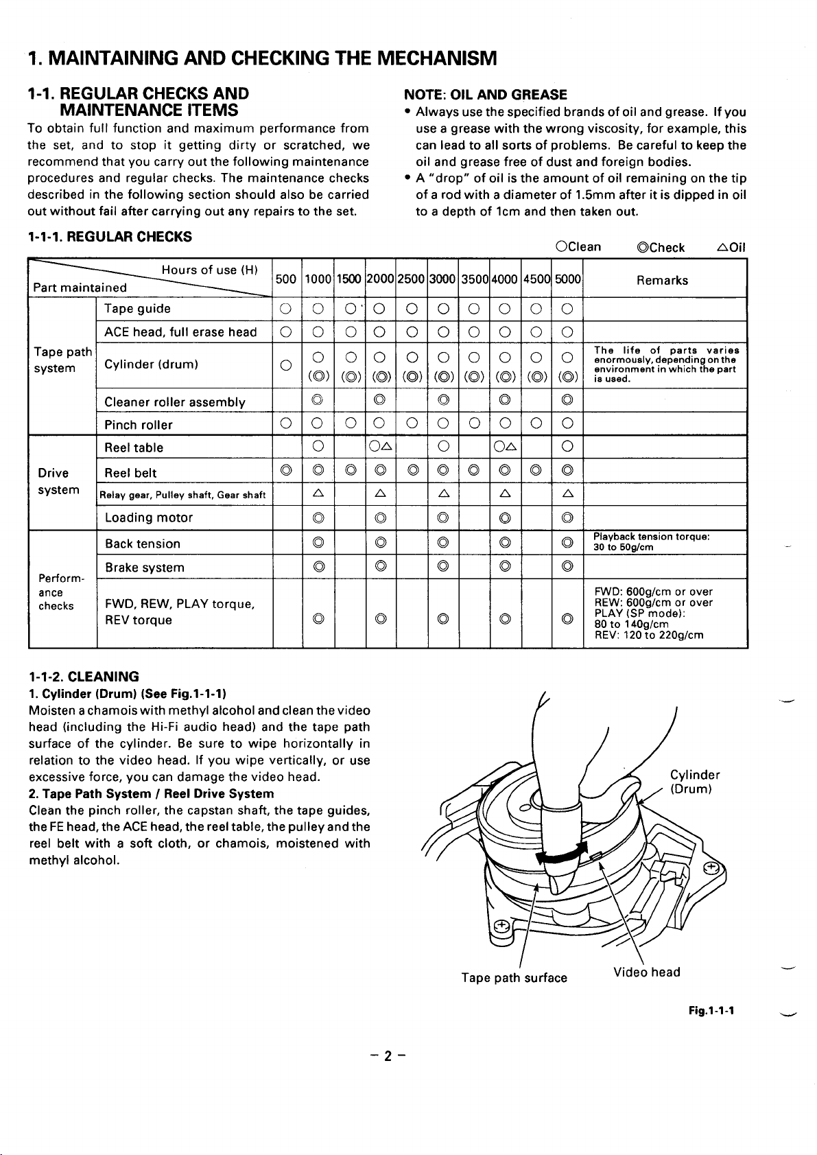
1-1-2. CLEANING
1. Cylinder (Drum) (See Fig.1-l-1)
Moisten a chamois with methyl alcohol and clean the video
head (including the Hi-Fi audio head) and the tape path
surface of the cylinder. Be sure to wipe horizontally in
relation to the video head. If you wipe vertically, or use
excessive force, you can damage the video head.
2. Tape Path System / Reel Drive System
Clean the pinch roller, the capstan shaft, the tape guides,
the FE head, the ACE head, the reel table, the pulley and the
reel belt with a soft cloth, or chamois, moistened with
methyl alcohol.
-2-
Tape path’ surface
.—
Video head
Fig.1-1-1 -
Page 3
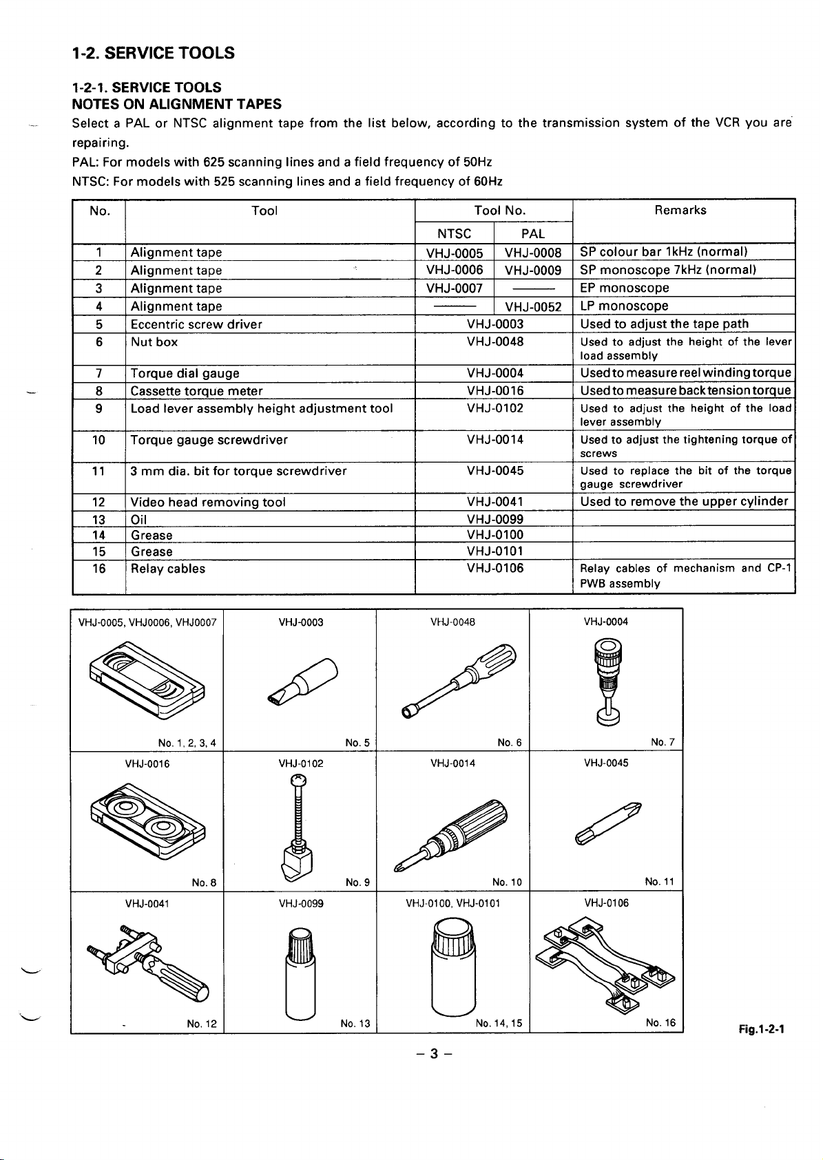
1-2. SERVICE TOOLS
1-2-1. SERVICE TOOLS
NOTES ON ALIGNMENT TAPES
..
Select a PAL or NTSC alignment tape from the list below,
repairing.
PAL: For models with 625 scanning lines and a field frequency of 50Hz
NTSC: For models with 525 scanning lines and a field frequency of 60Hz
according
to the transmission
system Ot the VCH you are
. . . ---
No.
I
1 Alignment tape
2 Aiianment taDe VHJ-0006
3 I Alignment tape
4 Alignment tape
Eccentric screw driver
5
Nut box
6
Torque dial gauge
7
8 Cassette torque meter VHJ-0016
Load lever assembly height adjustment tool
9
10 Torque gauge screwdriver VHJ-0014
11
3 mm dia. bit for torque screwdriver VHJ-0045 Used to replace the bit of the torque
I
12 Video head removing tool
13 Oil VHJ-0099
14
Grease VHJ-0100
15
Grease VHJ-0101
16 Relay cables
Tool Tool No. Remarks
NTSC
VHJ-0005
VHJ-0007 I — I EP monoscope
VHJ-0003
VHJ-0048
VHJ-OO04
VHJ-0102
I
VHJ-0041
VHJ-0106 Relay cables of mechanism and CP-1
I
PAL
VHJ-0008 SP colour bar lkHz (normal)
VHJ-0009 SP monoscoDe 7kHz (normal)
VHJ-0052
LP monoscope
Used to adjust the tape path
Used to adjust the height of the lever
load assembly
Used tomeasurereel winding torque
Used to measure backtensiontorque
Used to adjust the height of the load
lever assembly
Used to adjust the tightening torque of
screws
gauge screwdriver
I
Used to remove the upper cylinder
PWB assembly
VHJ-0005,VHJOO06,VHJOO07 VHJ-0003 VHJ-0048 VHJ-0004
a
No.1,2,3,4
VHJ-0016
+8
VHJ-0041 VHJ-0099 VHJ-0100, VHJ-0101 VHJ-O1O6
_
No. 12 No, 13
&
No.5
VHJ-0102 VHJ-0014 VHJ-0045
~ N
!!!
410
/
No. 6
‘lNo.
l!!!!!
No. 14,15
%
!
No. 7
No. 16
Fig.1-2-l
–3-
Page 4
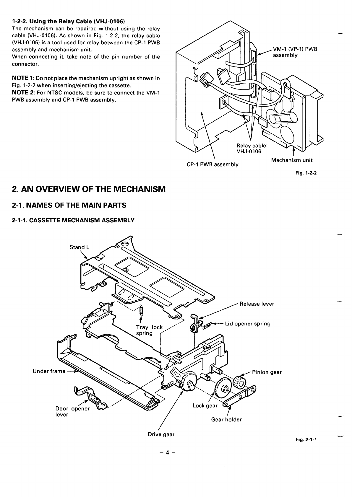
1-2-2. Using the Relay Cable (VHJ-0106)
The mechanism can be repaired without using the relay
cable (VHJ-0106). As shown in Fig. 1-2-2, the relay cable
(VHJ-O1O6) is a tool used for relay between the CP-I PWB
assembly and mechanism unit.
When connecting it, take note of the pin number of the
connector.
NOTE 1: Do not place the mechanism upright as shown in
Fig. 1-2-2 when inserting/ejecting the cassette.
NOTE 2: For NTSC models, be sure to connect the VM-I
PWB assembly and CP-I PWB assembly.
\
2. AN OVERVIEW OF THE MECHANISM
2-1. NAMES OF THE MAIN PARTS
2-1-1. CASSEITE MECHANISM ASSEMBLY
A
\
CP-I PWB assembly
Mechanism unit
Fig. 1-2-2
e lever
pring
Under fl
nion gear
—-
Gear holder
/
Drive gear
Fig. 2-1-1 —
–4–
Page 5
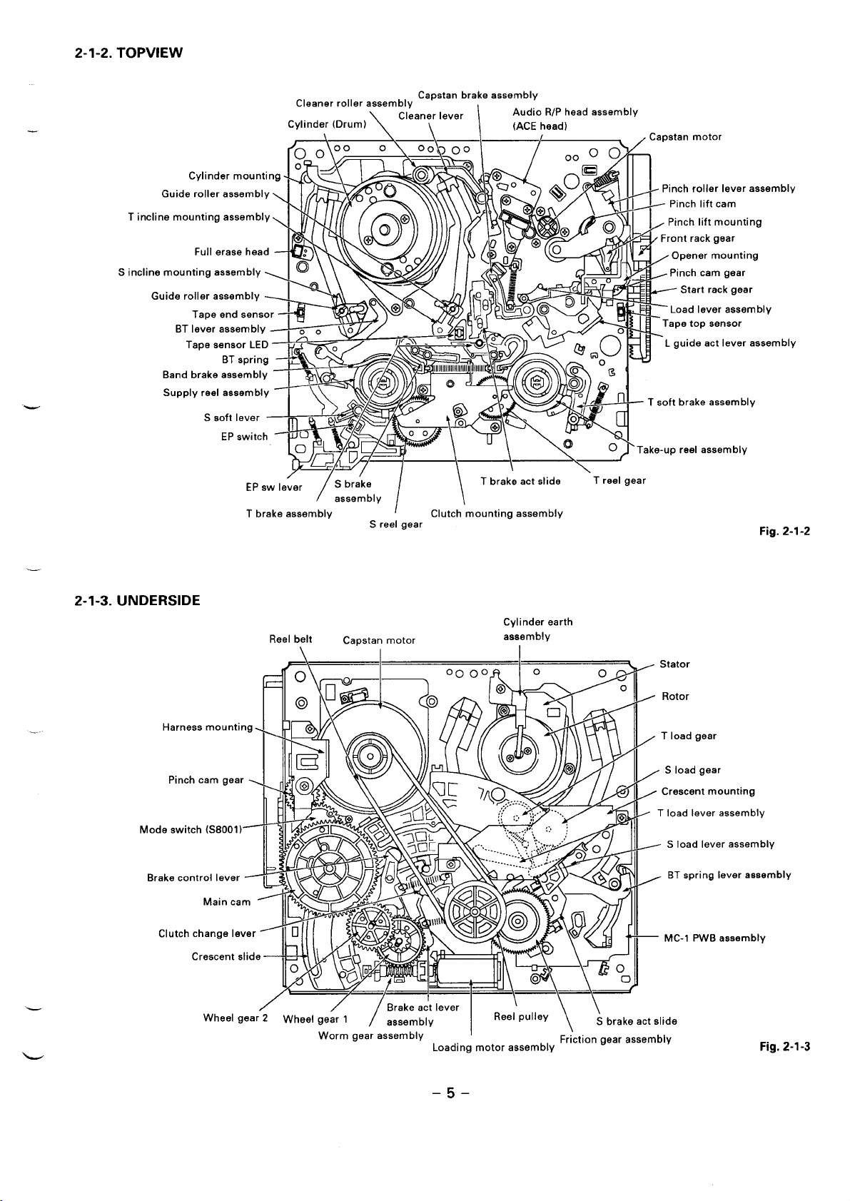
2-1-2. TOPVIEW
T in
S incl
Claaner roller aaaembly
Cylinder (Drum)
/ /Sbr;ke I
EP aw lever
T brake asaembly
/ aaaembly
Cleaner lever
\\
.— ,.— ,
/
S reel gear
Capstan brake assembly
Audio R/P head aasembly
(ACEhead)
I
\ Tbrake act slide ‘Treel gear
\
Clutch mounting assembly
. .
embly
Y
embly
Fig. 2-1-2
2-1-3. UNDERSIDE
Harneaa mounting
Pinch cam gear
Mode switch (S8001 )
Brake control lever ~~~~)
Clutch chanrae Ievar
Cylinder earth
Reel belt
Capatan
motor
aaaembly
Al 1
II@ \YY
LX
Main cam >
N AA (
II
h
o
c-c_enta,ide----!b4lLXil73
Whael gear 2 Wheel gear 1
/
/
Worm gear assembly
/Brake ac’t lever I i \ \
/ aeaembly
Loading motor assembly
Reel pulley
I
, Stator
= Rotor
/ T load gear
z S load gear
> Crescent mounting
, T load lever eeaembly
-- S load lever aasembly
, BT spring lever assembly
— MC-1 PWB aaaambly
S brake act slide
\
Friction gear aasembly
Fig. 2-1-3
-5-
Page 6
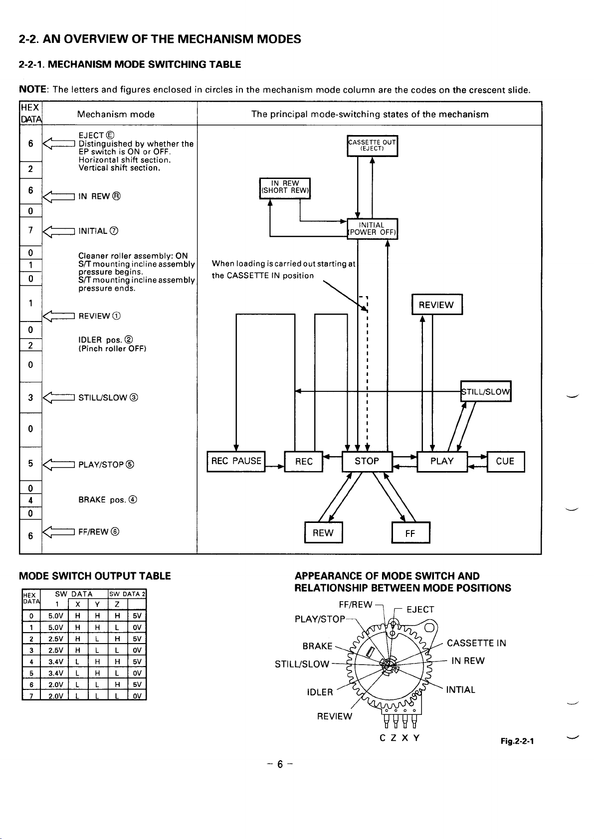
2-2. AN OVERVIEW OF THE MECHANISM MODES
2-2-1. MECHANISM MODE SWITCHING TABLE
NOTE: The letters and figures enclosed in circles in the mechanism mode column are the codes on the crescent slide.
MODE SWITCH OUTPUT TABLE
HEX
DATA
SW DATA
1 x ‘f z
5.OV H H H 5V
o
1 5.OV H H L Ov
2.5V H L H 5V
2
2.5V H L L Ov
3
4 3.4V L H H 5V
5 3.4V L H L Ov
6 2.OV L L H 5V
7 2.OV L L L Ov
SW DATA2
APPEARANCE OF MODE SWITCH AND
RELATIONSHIP BETWEEN MODE POSITIONS
FF/REvv ~ ~ EJECT
STIL
CZXY
-6-
E
IN
Fig.z-z-l -
Page 7
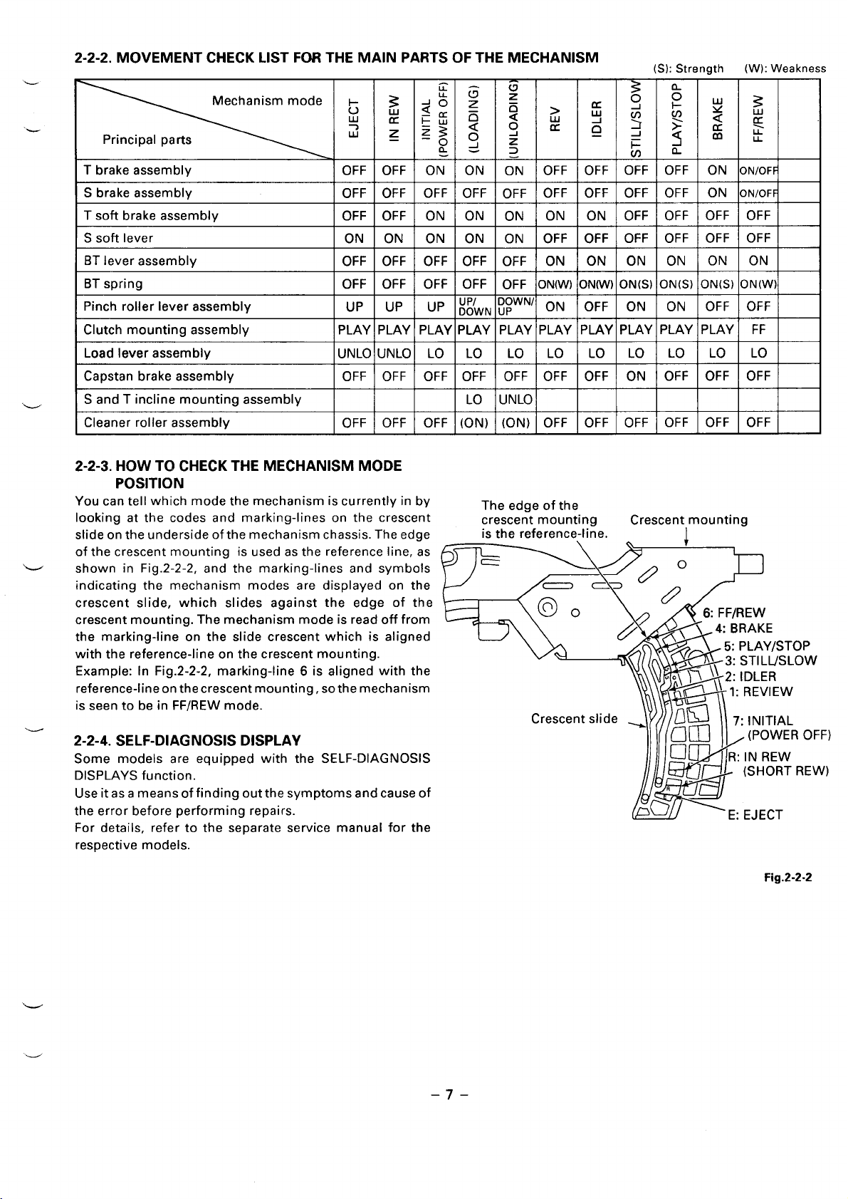
(S): Strength (W): Weakness
L
g
Mechanism mode
Principal parts
T brake assembly
S brake assembly
T soft brake assembly
S soft lever
BT lever assembly
BT spring
Pinch roller lever assembly
Clutch mounting assembly PLAY PLAY PLAY PLAY PLAY PLAY PLAY PLAY PLAY PLAY FF
Load lever assembly
Capstan brake assembly
S and T incline mounting assembly
Cleaner roller assembly
L
2-2-3. HOW TO CHECK THE MECHANISM MODE
POSITION
You can tell which mode the mechanism is currently in by
looking at the codes and marking-lines on the crescent
slide ontheunderside of the mechanism chassis. The edae
of the crescent mounting is used as the reference line, as
v
-
shown in Fig.2-2-2, and the marking-lines and symbols
indicating the mechanism modes are displayed on the
crescent slide, which slides against the edge of the
crescent mounting. The mechanism mode is read off from
the marking-line on the slide crescent which is aligned
with the reference-line on the crescent mounting.
Example: In Fig.2-2-2, marking-line 6 is aligned with the
reference-l ineonthecrescent mounting, sothe mechanism
is seen to be in FF/REW mode.
2-2-4. SELF-DIAGNOSIS DISPLAY
Some models are equipped with the SELF-DIAGNOSIS
DISPLAYS function.
Useitas ameansoffinding outthesymptoms andcauseof
the error before performing repairs.
For details, refer to the separate service manual for the
respective models.
;
7 ~
w
OFF OFF ON ON ON OFF OFF OFF
OFF OFF OFF OFF OFF OFF OFF OFF
OFF OFF ON ON ON ON ON OFF OFF OFF OFF
ON ON ON ON ON OFF OFF OFF
OFF OFF OFF OFF OFF ON
OFF OFF OFF OFF OFF ON(W) ON(W) ON(S) ON(S) ON(S) ON(W)
UP UP
UNLO UNLO LO LO LO LO LO LO LO LO LO
OFF OFF OFF OFF OFF OFF OFF ON
OFF OFF OFF (ON) (ON) OFF OFF OFF
$
K
z
J
~fi
g3 o
g’
5
~
: J
- “ _
up ;;tWN
LO UNLO
The edge of the
crescent mounting
is the reference-line.
~ R
cc
z
3
DOWNI ON
UP
ON ON ON ON ON
OFF ON ON OFF OFF
3
q p w ~
J
: $ : :
Q
i=
(n
OFF ON ONIOFF
OFF ON ONIOFF
OFF OFF OFF
OFF OFF OFF
OFF OFF OFF
Crescentlmounting
-1
L
z
UJ
m
LL
)
–7–
Fig.2-2-2
Page 8

3. DISASSEMBLING THE MAIN PARTS
OF THE MECHANISM
POINTS TO NOTE
●
When fitting the parts of the mechanism, refer to the
“Assembly Notes”,
assembly order.
●
Dis-assembly and assembly should be carried out in
EJECT mode unless a movement mode is explicitly
specified. EJECT mode is the state in which the cassette
tape has been ejected.
●
Clamps are used to prevent parts coming loose. When
removing a clamp, be careful not to force it, as this can
result in damage.
3-1. HOW TO MAKE THE MECHANISM
MOVE
In order to check a movement such as front loading, front
unloading, tape loading, tape unloading, raising/lowering
and pressing the pinch roller, you will need to operate the
loading motor. There are two methods of operating the
loading motor, and these are explained in sections 3-1-1
and 3-1-2. The above movements can also be performed
without operating the loading motor, by following the
method explained in section 3-1-3.
3-1-1. HOW TO OPERATE THE LOADING MOTOR
USING A DC VOLTAGE SUPPLY
(See Fig.3-l-1)
1) Remove the power plug from the socket.
2) Remove ~he top cover, front cabinet assembly and
bottom cover.
3) Supply a DC voltage in the range 5V between the
MOTOR (+) wire and the MOTOR (-) wire on the CP-I
PWB assembly. To make the loading motor rotate in
the PLAY or FF/REW direction, the positive terminal
should be connected to the MOTOR (+) wire, and the
negative terminal to the MOTOR (–) wire. To make it
rotate in the EJECT direction, connect the positive
terminal to the MOTOR (-) wire, and the negative
terminal to the MOTOR (+) wire.
When rotating the loading motor inthe EJECT direction
with a tape slacken, stop the rotation of the loading
motor before beginning front unloading.
Rotate the capstan motor with your hand, wind the
slacked part of the tape, and rotate the loading motor
in the EJECT direction again.
NOTE 1: When carrying out front loading, release the lock
by pressing down the tray lock lever@ and the lid opener
lever @ of the cassette mechanism assembly (shown in
Fig.3-2-2) in the direction of the arrow.
NOTE 2: When the loading motor stops rotating, following
the completion of an operation such as tape loading or
front unloading, switch off the DC voltage supply.
and proceed in the reverse of dis-
Bottom side
Motor (+) wire
Motor (-) wire
3-1-2. OPERATING THE LOADING MOTOR BY THE
MANUAL METHOD (See Fig.3-l-2)
1) Refer to section 3-2 and install the mechanism unit.
2) Using your finger, turn the loading motor located at
the rear of the mechanism unit. For EJECT, turn the
loading motor in the direction of the arrow on the
loading motor. For PLAY or FF/REW, turn it in the
opposite direction.
When rotating the loading motor in the EJECT direction
with a tape slacken, stop the rotation of the loading
motor before beginning front unloading.
Rotate the capstan motor with your hand, wind the
slacked part of the tape, and rotate the loading motor _
in the EJECT direction again.
When carrying out front loading, release the lock
by pressing down the tray lock lever @ and the lid
opener lever @ of the cassette mechanism assembly
(shown in Fig.3-2-2).
The arrow which showtha direction of EJECT
Front side
Fig.3-l-l
a
t
Fig.3-l-2
Loading motor
3-1-3. MAKING THE MECHANISM MOVE USING
THE MANUAL METHOD
1) Refer to section 3-2 and remove the mechanism unit.
2) Refer to section 3-15 and remove the gear wheel 2.
3) If you turn the main cam anticlockwise, the mechanism
will switch to a mode such as PLAY or FF/REW. To
switch from FF/REW mode to EJECT mode, turn the
main cam clockwise.
d
L
–8–
Page 9
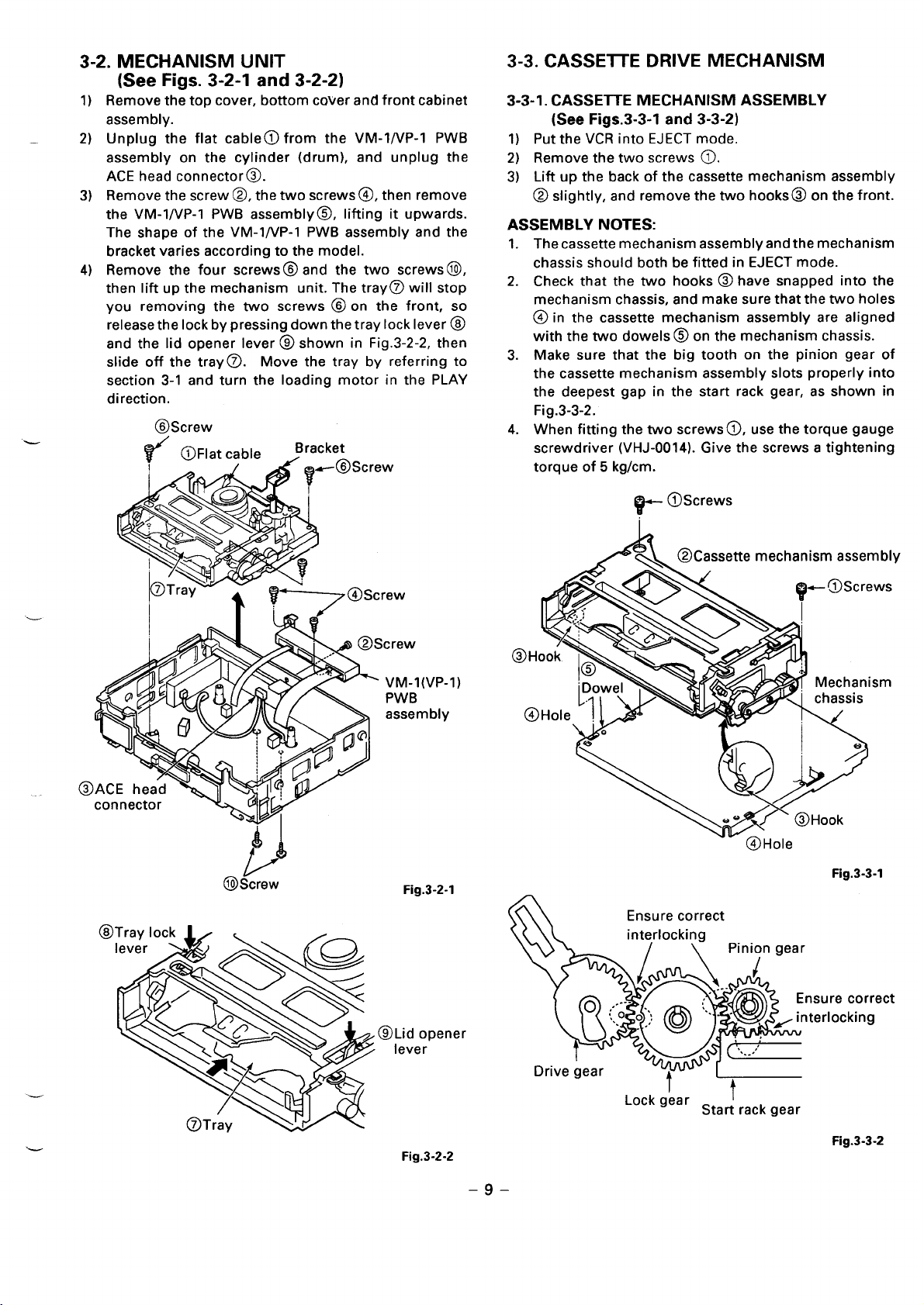
3-2. MECHANISM UNIT
(See Figs. 3-2-1 and 3-2-2)
Remove the top cover, bottom cover and front cabinet
1)
assembly.
2)
—
Unplug the flat cable@l from the VM-1/VP-l PWB
assembly on the cylinder (drum), and unplug the
ACE head connector@.
3)
Remove the screw @, the two screws@, then remove
the VM-1/VP-l PWB assembly@, lifting it upwards.
The shape of the VM-1/VP-l PWB assembly and the
bracket varies according to the model.
4)
Remove the four screws@ and the two screws@,
then lift up the mechanism unit. The tray@ will stop
you removing the two screws @ on the front, so
release the Iockbypressing down the tray lock lever @
and the lid opener lever @ shown in Fig.3-2-2, then
slide off the tray~.
section 3-1 and turn the loading motor in the PLAY
direction.
@Screw
IFI ““Iat cable
<0
Move the tray by referring to
Bracket
I A ~e@Screw
3-3. CASSEITE DRIVE MECHANISM
3-3-1. CASSEITE MECHANISM ASSEMBLY
(See Figs.3-3-l and 3-3-2)
1) Put the VCR into EJECT mode.
2) Remove the two screws @).
3) Lift up the back of the cassette mechanism assembly
@ slightly, and remove the two hooks@ on the front.
ASSEMBLY NOTES:
1.
The cassette mechanism assembly and the mechanism
chassis should both be fitted in EJECT mode.
2.
Check that the two hooks @ have snapped into the
mechanism chassis, and make sure that the two holes
@in the cassette mechanism assembly are aligned
with the two dowels @ on the mechanism chassis.
Make sure that the big tooth on the pinion gear of
3.
the cassette mechanism assembly slots properly into
the deepest gap in the start rack gear, as shown in
Fig.3-3-2.
4.
When fitting the two screws@, use the torque gauge
screwdriver (VHJ-0014). Give the screws a tightening
torque of 5 kg/cm.
~ @Screws
@
A“
1A
‘k
.“Yi
#
.
..-’
.. ,
@Screw
VM-I(VP-1)
PWB
assembly
Y
Mechanism
chassis
f@Hole
Fig.3-3-l
Fig.3-2-l
sure correct
erlocking
Lock gear
-
Fig.3-2-2
–9–
I
Start rack gear
Fig.3-3-2
Page 10
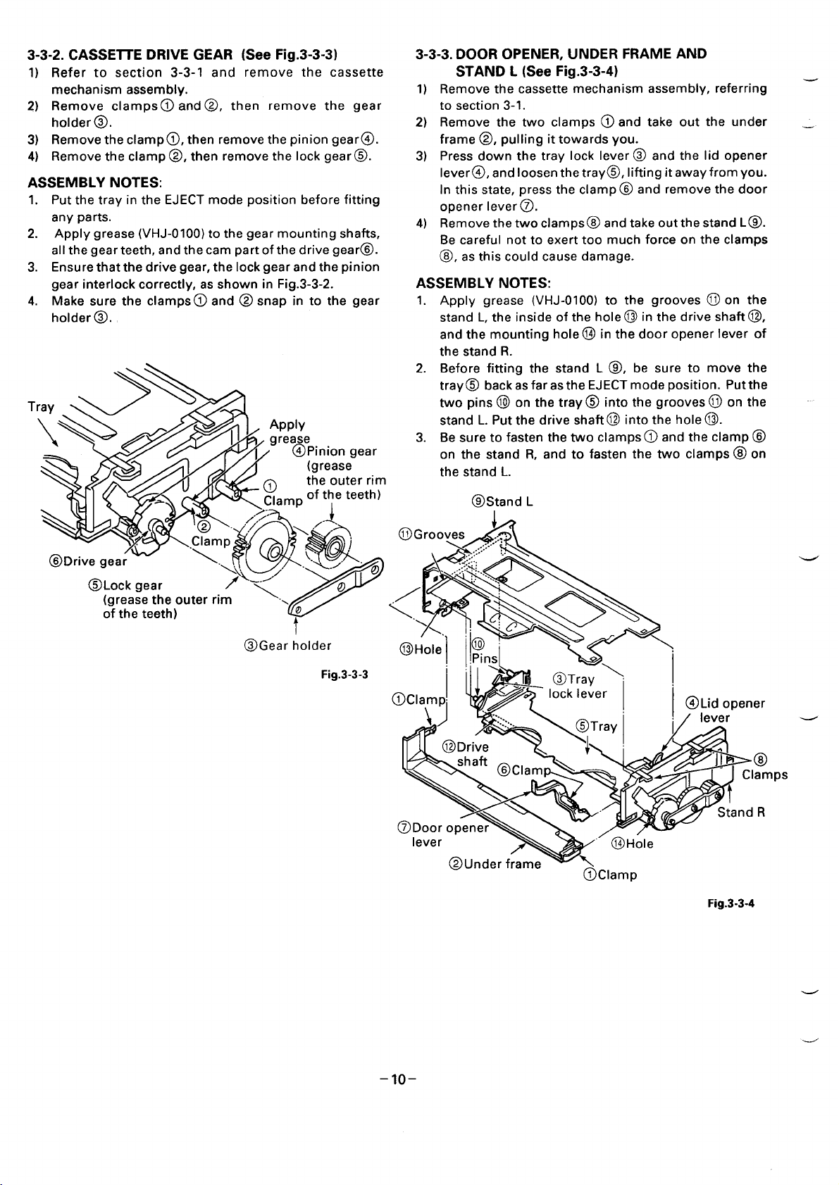
3-3-2. CASSEITE DRIVE GEAR (See Fig.3-3-3)
1) Refer to section 3-3-1 and remove the cassette
mechanism assembly.
2) Remove clampso and @, then remove the gear
holder @.
3) Remove the clampo, then remove the pinion gear@.
4) Remove the clamp@, then remove the lock gear@.
ASSEMBLY NOTES:
1. Put the tray in the EJECT mode position before fitting
any parts.
2. Apply grease (VHJ-0100) to the gear mounting shafts,
allthe gear teeth, and the cam part of the drive gear@.
3. Ensure that the drive gear, the lock gear and the pinion
gear interlock correctly, as shown in Fig.3-3-2.
4. Make sure the clamps@) and @ snap in to the gear
holder @.
T
$)$@
“ I , %J~epiniongear
q
A
- Q._R of the teeth)
.
(grease
the outer rim
3-3-3. DOOR OPENER, UNDER FRAME AND
STAND L (See Fig.3-3-4)
Remove the cassette mechanism assembly, referring —
1)
to section 3-1.
Remove the two clamps @ and take out the under _
2)
frame @, pulling it towards you.
Press down the tray lock lever @ and the lid opener
3)
lever@, and loosen the tray@, lifting it away from you.
In this state, press the clampo and remove the door
opener Iever@.
4)
Remove the two clamps@ and take out the stand L@.
Be careful not to exert too much force on the clamps
@, as this could cause damage.
ASSEMBLY NOTES:
1. Apply grease (VHJ-0100) to the grooves @ on the
stand L, the inside of the hole@ in the drive shaft@,
and the mounting hole@ in the door opener lever of
the stand R.
2. Before fitting the stand L o, be sure to move the
tray@ back as far as the EJECT mode position. Put the
two pins @l on the tray@ into the grooves@ on the
stand L. Put the drive shaft@ into the hole@.
3. Be sure to fasten the two clamps@ and the clamp@
on the stand R, and to fasten the two clamps @ on
the stand L.
@.tand L
@Gear holder
Fig.3-3-3
@Hole
@ !-
Pinsl
er
@
amps
R
@Clamp
Fig.3-3-4
–lo–
Page 11
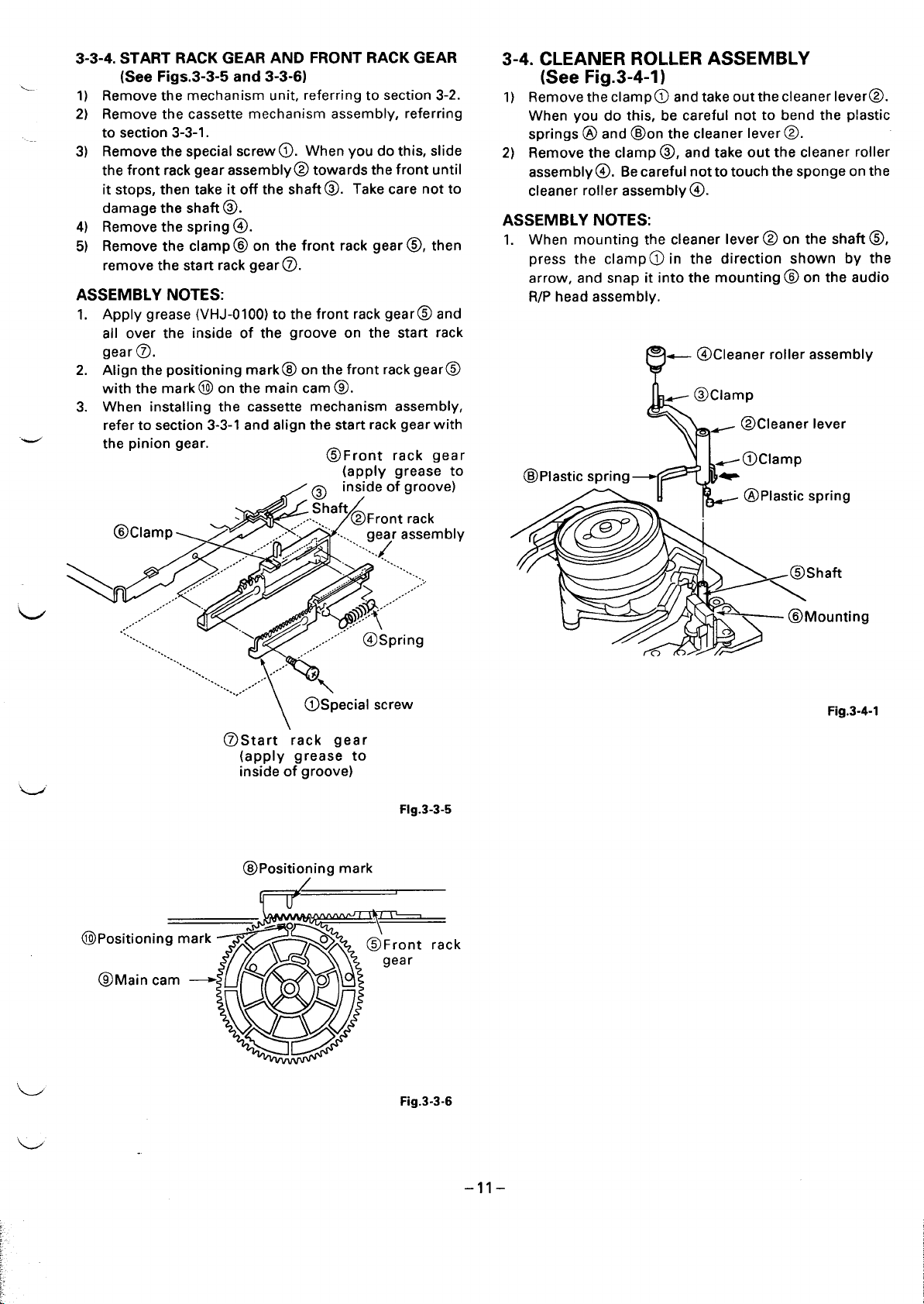
3-3-4. START RACK GEAR AND FRONT RACK GEAR
‘Mounting
.-
\
*A
(SeeFigs.3-3-5 and 3-3-61
1)
Remove the mechanism unit, referring to section 3-2.
2)
Remove the cassette mechanism assembly, referring
to section 3-3-1.
Remove the special screw o. When you do this, slide
3)
the front rack gear assembly@ towards the front until
it stops, then take it off the shafto. Take care not to
damage the shaft@.
4)
Remove the spring @.
Remove the clamp@ on the front rack gear@, then
5)
remove the start rack gear @.
ASSEMBLY NOTES:
Apply grease (VHJ-0100) to the front rack gear@ and
1.
all over the inside of the groove on the start rack
gearo.
2.
Align the positioning mark@ on the front rack gear@
with the mark @ on the main cam ~.
When installing the cassette mechanism assembly,
3.
refer to section 3-3-1 and align the start rack gear with
the pinion gear.
@Clamp
/ .....’”--’’”-””
,..,
,,,
.,-
...
...”
.....
...
%.
‘%..
....>
,*
/ -,+x, ‘-;’:..
,.., .- ‘-
,,~
,.-,-
.\
~fl&/ ,...”’-” @Spring
...
...
.... ,., ”
..-”
p
... .,. -’
.,.
\
@Start “rack gear
~apply grease to
mslde of groove)
@Front rack gear
!ap.ply grease to
y @ Ins;de of groove)
; Shaft
J
.,..,.
>.,”
/ .-
,.,
,.
@Front rack
““’~.(
‘y ,. -%..
,..-
““””‘“2 ,...””’;;
$@’”
‘ 1
,..
gear assembly
‘Y
@Special screw
..
3-4. CLEANER ROLLER ASSEMBLY
(See Fig.3-4-1)
1) Remove the clamp@ and take out the cleaner lever@.
When you do this, be careful not to bend the p!astic
springs @ and @on the cleaner lever@.
2) Remove the clamp o, and take out the cleaner roller
assembly@. Becarefui nottotouch the sponge on the
cleaner roller assembly@.
ASSEMBLY NOTES:
1. When mounting the cleaner lever@ on the shaft@,
press the clamp@ in the direction shown by the
arrow, and snap it into the mounting @ on the audio
RIP head assembly.
- 4 Cleaner roller assembly
o
~
- @Clamp
- @Cleaner lever
~@ Clamp
@Plastic spring -
3-
*7i?\
_ @Plastic spring
Shaft
Fig.3-4-l
@Positioning mark
@lMain cam
Flg.3-3-5
@Positio~ing mark
Fig.3-3-6
–11–
.,,
F.
Page 12

3-5. CYLINDER (DRUM)
eA@ROundhO’
3-5-1. UPPER CYLINDER ASSEMBLY
(UPPER DRUM) (See Figs. 3-5-1,3-5-2,3-5-3,
3-5-4)
There are two types of cylinders, one that can be
disassembled into the upper cylinder (upper drum) and
lower cylinder (lower drum) and one that cannot. For that
typethatcannot, replace thecylinder assembly asawhole.
Remove the two screws @ (See Fig.3-5-1).
1)
2)
First, tighten the handle@ of the video head
removing tool (VHJ-0041), then screw the two long
screws @ evenly into the two screw holes @ in the
upper cylinder assembly (upper drum) @) (See Fig.
3-5-2).
Hold the tool (VHJ-0041) so that the upper cylinder
3)
assembly (upper drum) @ does not rotate, and at the
same time, turn the handle@ clockwise, and remove
the upper cylinder assembly (upper drum)@.
4)
Remove the tool (VHJ-0041) from the upper cylinder
assembly @.
@Screws
ASSEMBLY NOTES:
1. When carrying out assembly, the CH-I head on the
upper cylinder assembly (upper drum)@ and the lower
cylinder assembly (lower drum) @ must be aligned.
The CH-1 head on the upper cylinder assembly@ bears _
a code@ such as 2N2S-V, 2N4N, or 4H6N, as shown in
Fig.3-5-3. The CH-I on the lower cylinder assembly@
has a round hole o, as shown in Fig.3-5-4. Assemble
the parts so that the round hole @l is next to the code
@on the upper cylinder assembly.
2. Be careful not to scratch the tape path surface of the
cylinder. After replacing the cylinder, clean the tape
path surface of the cylinder.
3. After replacing the upper cylinder assembly, dothetape
path adjustment as instructed in section 4-3 and do the
switching position adjustment of the servo circuit.
@Upper cylinder assembly
(upper drum)
.---------------
I
@Handle
@
Screw
holes
& ~ ‘vHJ-004’)
1
I
m
/
‘~
‘@’
k
*DJ]
Fig.3-5-l
!- Video head removing tool
@ Upper cylinder assembly
(upper drum)
@ Lower cylinder assembly
(lower drum)
[EXCEPTFOR2-HEADMONAURALMODELS]
[2-HEAD MONAURAL MODELS ONLYI
@ Round
y%
0’
a$
A
W/ ‘ Screw holes
@Lower cylinder
- assembly
Fig.3-5-3 _
(lower drum)
Lower cylinder
assembly
(lower drum)
w
Fig.3-5-2
–12-
Fig.3-5-4
d
Page 13

3-5-2. CYLINDER (DRUM) UNIT (See Fig.3-5-5)
1) Put the mechanism into EJECT mode.
2) Refer to section 3-2 and remove the VM-1/VP-l PWB
assembly
3) Refer to section 3-4 and remove the cleaner lever.
4) Remove the two screwso and take off the bracket @.
The bracket shape varies according to the model.
5) Remove the three screws@. Taking care not to
scratch or soil the tape path surface of the cylinder
(drum), lift the mounting cylinder@ slightly, and
keeping it raised.
ASSEMBLY NOTES:
Apply grease (VHJ-0100) to the rails (front and rear) of
1.
the cylinder mounting@ (grease the parts which come
in contact with the S and Tincline mounting assembly).
2.
Align the two dowels@ on the mounting cylinder
@ with the two holeso on the mechanism chassis.
Check that connector is inserted in the CP-I PWB
assembly.
After assembly, clean the tape path surface of the
3.
L
cylinder (drum).
4.
After replacing the cylinder unit, do the tape path
adjustment as instructed in section 4-3, and do the
switching position adjustment of the servo circuit.
@lScrew
./ \ @Bracket (shaDe varies
e5\-
“model)
3-5-3. CYLINDER MOTOR (ROTOR AND STATOR)
(See Fig.3-5-6)
1) Refer to section 3-5-2 and remove the cylinder unit.
2) If you have removed the mechanism unit, remove the
screw @ and remove the cylinder earth assembly@.
3) Remove the two screws@, the rotor@ and the
spacer @.
4) Remove the three screws@ and the stator @.
ASSEMBLY NOTES:
When fitting the rotor@, align the long hole~ -beside
1.
the triangular mark on the rotor@ - with the hole @
in the rotor disk.
2.
When fitting the screws@ and @, use the torque
gauge screwdriver (VHJ-0014). give the screws
tightening torque of 3 kglcm.
Align the dowel (@ on the cylinder earth assembly@
3.
with the hole @ in the chassis.
if you have removed the cylinder unit, after assembly,
4.
do the tape path adjustment as instructed in section
4-3, and do the switching position adjustment of the
servo circuit.
@Screws
/9
@Rot~
@
&
@lLong hole (used for
alignment when fitting
the rotor)
A
‘>
Triangularmark
a
*YV J
I I_= mounting
L
L
@Cyiinder
Fig.3-5-5
Wspacer ~!
~Ho,e6s:=// ‘@Ho’e
when fitting the rotor)
–13-
/
~@Dow$
@Screws
to r
@Cylinder
1
earth
assembly
Fig.3-5-6
Page 14

3-5-4. CYLINDER ASSEMBLY (See Fig.3-5-7)
1) Refer to sections 3-5-2 and 3-5-3, and remove the
cylinder unit, the rotor, and the stator.
2) Remove the three screws@ and the cylinder
assembly @.
ASSEMBLY NOTES:
1. Be careful not to scratch or soil the top of the cylinder.
After fitting the cylinder, clean the surface.
2. Align the cylinder assembly@ with the two dowels@
on the cylinder mounting @.
3. After fitting the cylinder assembly, do the tape path
adjustment as instructed in section 4-3 and do the
switching position adjustment of the servo circuit.
,------------------------------------------ ,
R/P head assembly
cad)
@Hole
m“
o
IGI
,-----------......-------------.........
@Dowels
@cy
mo
3-6. FE HEAD AND ACE HEAD
\
u \
\,
~—
J
@Cylinder
assembly
rews
Fig.3-5-7
Fig.3-6-l
3-6-2. FULL ERASE HEAD (See Fig.3-6-2)
1) Unplug the connector from the full erase heado.
2) Remove the screw@ and the full erase heado.
ASSEMBLY NOTE:
1. After assembly, clean the full erase head~.
@Screw
@Full erase head
-.
3-6-1. AUDIO R/P HEAD ASSEMBLY (ACE HEAD)
(See Fig.3-6-1)
1) Unplug the connector from the audio R/P head
assembly (ACE head).
2) Remove the two screws@ and the audio RIP head
assembly (ACE head) @.
ASSEMBLY NOTES:
Align the holeo on the audio R/P head assembly
1.
(ACE head) with the pin@ on the chassis unit.
After assembly, check that the clamp@ on the cleaner
2.
roller assembly has snapped into the mounting of
the audio R/P head assembly (ACE head) @.
After assembly, clean the surface of the head with a
3.
soft cloth or chamois.
After assembly, refer to section 4-3, and adjust the
4.
head height, the azimuth and the tracking (X) position.
I
Fig.3-6-2
–14–
Page 15

3-7. CAPSTAN MOTOR
3-7-1. CAPSTAN MOTOR (See Fig.3-7-l )
1) Refer to section 3-2, then remove the mechanism unit.
2) Remove the two screws@, then remove the harness
mounting 0.
3) Remove the reel belt~.
4) Remove the three screws@ and the capstan motor@.
ASSEMBLY NOTES:
1. Check that connector@ is inserted in the CP-I PWB
assembly.
2. When fitting the three screwso, use the torque
gauge screwdriver (VHJ-0014). Give the screws a
tightening torque of 3.5 kglcm.
3. After assembly, clean the capstan shaft with a soft
cloth or chamois.
@Screws
3-7-2. CAPSTAN BRAKE ASSEMBLY (See Fig.3-7-2)
1) Remove the spring o.
2) Remove the clamp@, then remove the capstan brake
assembly o.
@Spring
,/
—
CaDstan shaft
@Reei belt
\
‘1
I&
<.
\~ (@Capstan
Fig.3-7-2
@;creks
Fig. 3-7-1
–15–
Page 16

3-8. LOADING MOTOR ASSEMBLY AND
WORM GEAR ASSEMBLY
(SeeF@.s-8-1)
1)
Refer to section 3-2 and remove the mechanism unit.
Remove the soldering on the lead wires@ of the
2)
loading motorassemblyfrom the MC-1 PWBassembly.
When you do this, be careful not to let the soldering
iron touch any other parts.
Press the clamp @, and remove the loading motor
3)
assembly@l and the damper@. Be careful not to exert
too much force on the clamp@.
Remove the worm gear assembly@. To maintain
4)
performance, do not dis-assemble the worm gear
assembly @.
ASSEMBLY NOTES:
Apply grease (VHJ-0010) to the teeth of the worm gear
1.
assembly.
2.
Check that the clamps@ and @ are securing the
loading motor assembly.
Check the polarity of the lead wires@ (the orange
3.
wire is the positive terminal, and the gray wire is the
negative terminal). After soldering the lead wires@,
adjust them so that they do not touch the friction gear
assembly.
3-9. PINCH ROLLER PRESSURE
MECHANISM
3-9-1. PINCH ROLLER LEVER ASSEMBLY
(See Fig.3-9-1)
Remove the clamp o, then remove the pinch lift
1)
mounting @.
Remove the spring o, then remove the pinch roller
2)
lever assembly@ offthepinch lift mounting@. Before
you do this, align the Indentation@ on the pinch roller
lever assembly@ with the clamp@ on the pinch lift
mounting @.
ASSEMBLY NOTE:
1. Be careful to keep the surface of the pinch roller free
of dust and dirt.
@Pinch roller lever
assembly
@lndent~tion
@Spring
I
@Worm gear assembly
p
Apply
‘~rease
@Damper
\
\, ~
]
~ N
@Loading motor assembly
@Lead wires
@
Clamps
Ii [\
L
_@ Clamp
.
/
\
‘> Orange:
positive
Gray:
negative
Fig.3-8-l
@Clamp
h’
A
lift mounting
.----...,l= @ClamP
,,-
(
.
--- r,
Fig.3-9-l
–16-
Page 17

3-9-2. PINCH LIIT CAM AND PINCH CAM GEAR
(See Figs.3-9-2 and 3-9-3)
Refer to section 3-2 and remove the mechanism unit.
1)
When you do this, make sure the mechanism is in
EJECT mode.
2)
Refer to section 3-9-1 and remove the pinch roller
lever assembly.
After removing thescrewo, undo thethreeclamps@,
3)
then remove the opener mounting o.
4)
Remove the clamp @ and the pinch lift cam@.
5)
Remove the pinch cam gear @.
ASSEMBLY NOTES:
1. Apply grease (VHJ-0100) around the shafto, all over
the teeth @ of the pinch cam gear ~, all over the
teeth of the pinch lift cam@, all over the cam grooves
@, and all over the “V Part@” of the opener mounting
@. APPIY 9rease WHJ-0101) to the outside of the
shaft @ and all over the top cam @ of the pinch cam
gear@.
u
2. Check that the positioning mark@ on the mode
switch@ isalignedwith the arrow@) on the MC-1 PWB
assembly, as shown in Fig:3-9-3. Then align the
triangular mark @ on the pinch cam gear@ with the
arrow @ on the MC-1 PWB assembly. After that,
align the round hole @ on the pinch lift cam @ with
the indentation @ on the pinch cam gear@,
If you have carried out the above alignments and the
pinch roller will still not move up and down or perform
the pressing movement correctly, refer to section
3-15 and check the alignment of the gear wheels 1
and 2, the main cam, and the mode switch.
@Triang.larmark , ~~ @Ro.nd hole
Q)
@Mode switch
2°
•*~~ on mode switch
(__’#dentati~
0
1
11Arrow on MC-1 PWB
assembly
@positioning marks
@Pinch lift cam
/
@)Pinch cam gear
Fig.3-9-3
00
m
u
cam
@
L
<.
Fig.3-9-2
–17–
Page 18

3-10. L GUIDE LEVER ASSEMBLY AND
LOAD LEVER ASSEMBLY
(SeeF@s.3-10-1)
1)
Refertosection 3-3 and remove the cassette mechanism
assembly.
Refer to sections 3-9-1 and 3-9-2 ,then remove the pinch
2)
roller lever assembly and the opener mounting.
After removing the washer @, remove the L guide
3)
act lever assembly@.
4)
Remove the special nut@, then remove the load lever
assembly @ and the L guide lever spring@.
ASSEMBLY NOTES:
Apply grease (VHJ-0100) to the toothed area@ of the
1)
L guide act lever assembly@ and around the shafts
@and@,
Refer to section 4-3 and adjust the height of the load
2)
lever assembly.
Hook the L guide lever spring@ into the stopper @
3)
and load lever assembly@ shown in Fig. A.
Put the pin @ of the L guide act lever assembly into
4)
the cam groove @ of the crescent slide.
@L guide lever spring
3-n, BT LEVER ASSEMBLY (See Fig.3-11-1)
Refer to section 3-2 and remove the mechanism unit.
1)
2)
Refer to section 3-3-1 and remove the cassette —
mechanism assembly.
Remove the BT spring@.
3)
4)
Remove the clamp@ on the underside of the –
mechanism chassis, then remove the BT lever
assembly @.
Remove the clamp @ on the band brake assembly@.
5)
Then, as shown in Fig. A, align the other end of the
band brake assembly with the protruding parts of the
BT lever assembly@ before removing it.
ASSEMBLY NOTES:
When fitting the BTleverassembly@, be careful not to
1.
bend the stopper@
assemblyo out of shape by knocking it against them.
Hookthe long hook of the BTspring@ into the BTlever
2.
assembly@, as shown in Fig. B.
After assembly, make sure that the mountings on
3.
both ends of the band brake assembly@ are
positioned as shown in Fig. C.
Afier assembly, refer to section 4-2-1, and make the
4.
appropriate adjustment.
or the S incline mounting
(@Special nut
@Load lever%
assembly
@L guide lever spring ~
assem:b&
@L guide
act lever
@pin ‘>
@Cam groov
Fig. A
‘7 o
‘\
%
e
@Load lever assembly
o
~
i
e
@Shaft
@Stopper
/
Fig.3-10-l
Prot
part
Fig.3-l 1-1
–18–
.-
Page 19

3-12. REEL DRIVE MECHANISM
3-12-1. REEL BELT, REEL PULLEY, FRICTION GEAR
ASSEMBLY AND CLUTCH CHANGE LEVER
(See Fig.3-12-1)
1)
Refer to section 3-2 and remove the mechanism unit.
Remove the reel belto from the reel pulley@.
2)
Take off the washer@ and remove the reel pulley@.
3)
4)
Take off the washer @ and remove the friction gear
assembly @.
Remove the clutch change spring @.
5)
6)
remove the clamp@ gripping the top of the
mechanism chassis, then remove the clutch change
Iever@.
Part A
,,--,
,79
@Hole “ ~“
%.R
A—
WScrews
+x’
1
+
i
$,
0
@Hole
v
_ @Clutch
mounting
assembly
ASSEMBLY NOTES:
1. After cleaning the shaftso and@, apply a drop of oil
(VHJ-0099) to each.
2. Be careful not to get any grease on the reel belto.
@Clutch
spring
@Clam
n gear
bly
@Shaft
Fig.3-12-2
3-12-3. S SOtT LEVER, SUPPLY REEL ASSEMBLY
AND S REEL GEAR (See Fig.3-12-3)
1) Remove the S soft spring @).
2) Remove the clamp@, then remove the S soft Iever@).
3) Refertosection 3-12-2 and remove theciutch mounting
assembly.
4) Refer to section 3-11 and remove the band brake
assembly, then remove the supply reel assembly @
and the S reel gear@.
ASSEMBLY NOTES:
1. After cleaning the shafts@ and o, apply a drop of oil
(VHJ-0099) to each.
2. After assembly, clean the side of the supply reel
assembly @.
OS soft lever
@Supply reel
assembly
Fig.3-12-l
3-12-2. CLUTCH MOUNTING ASSEMBLY
(See Fig.3-12-2)
1) Refer to section 3-3-1 and remove the cassette
mechanism assembly.
2) Refer to section 3-12-1 and remove the reel pulley.
3) Remove the two screws @, then remove the clutch
mounting assembly @.
ASSEMBLY NOTES:
1. Align the two holes @ with the shafts @l and @. Be
careful not to press part A of the clutch mounting
assembly @ against the band brake assembly.
2. After assembly, make sure that the clamp on the
clutch change lever has snapped into the chassis.
–19-
m soft
spring
@Clamp
\
I
@S reel
gear
aft
Fig.3-12-3
Page 20

3-12-4. T SOFT BRAKE ASSEMBLY, TAKE UP REEL
ASSEMBLY, T REEL GEAR (See Fig.3-12-4)
1) Remove the T soft spring@.
2) Remove the clamp @ , then remove the T soft brake
assembly @.
3) Refer tosection3-12-2 and remove the clutch mounting
assembly.
4) Pressing the T brake assembly@ in the direction of the
arrow, remove the take up reel assembly@ and the T
reel gear 6.
ASSEMBLY NOTE:
1. After cleaning the shaftso and @), apply a drop of oil
(VHJ-0099) to each.
3-13. BRAKES
3-13-1. S BRAKE ASSEMBLY, T BRAKE ASSEMBLY,
T BRAKE ACT SLIDE (See Fig.3-13-l )
1) Refer to section 3-3-1 and remove the cassette _
mechanism assembly.
2) Remove the two clamps o, then remove the T brake
act slide @. (Note: You can remove the S brake
assembly @ and the T brake assembly @ without
removing the T brake act slide @.)
3) Remove the brake spring o.
4) Remove the two clamps @) simultaneously, then
remove the T brake assembly@.
5) Remove the clamp@, then remove the S brake
assembly @.
@T reel gear
@T brake
assembly,
J&.
o
b
\l
Take up reel
assembly
@lT soft brake
I
sembly
T soft
spring
Fig.3-12-4
ASSEMBLY NOTES:
1. Apply grease (VHJ-0100) to the shafts@ and@.
2. When fitting the T brake act slide@, align the mark@)
with the shafto.
@Mark @T,brake act slide
-.
@Brake spring ‘clamp
/’; \
d
Il.
Clamp
@T brake
assembly
OS brak~
assembly
-20-
Fig.3-13-l
Page 21

3-13-2. BRAKE CONTROL LEVER AND BRAKE ACT 3-13-3. S BRAKE ACT SLIDE AND BT SPRING LEVER
@~tiYF>’”@
LEVER ASSEMBLY (See Fig.3-13-2)
Refer to section 3-2 and remove the mechanism unit.
1)
2)
Refer to section 3-15 and remove the wheel gear 2.
Refer to sections 3-12-1, then remove the reel belt and
3)
the reel pulley.
4)
Remove the clamp@), then remove the wheel gear I@.
Remove the clutch change spring @.
5)
Remove the clamps @) and@, then remove the brake
6)
control lever@. Remove the clamp@ on the topside
of the mechanism chassis.
7)
Remove the brake return spring @.
Refer to section 3-8 and remove the worm gear
8)
assembly.
Remove the clamp@ and clamp @, then remove the
9)
brake act lever assembly@. To maintain the
performance of the brake act Ieverassembly@, do not
disassemble it.
ASSEMBLY
Apply grease (VHJ-0100) to the shafts@ and @), to the
4
1.
teeth of the wheel gear 1 @, and to the pin @ of the
brake control lever@.
2.
Put the pin@ of the brake control lever@ into the cam
groove @ of the crescent slide.
3.
Before fitting the wheel gear 1 @, align the hole @
with the hole @ on the mechanism chassis.
4.
Refer to section 3-15 and align the wheel gear 2.
NOTES:
1)
2)
3)
4)
5)
ASSEMBLY NOTES:
1. Apply grease (VHJ-0100) to the shaft@ shown in Fig.
2. After mounting the BTspring lever assembly@ on the
3. Make sure that the clamps @,@ and@ have snapped
ASSEMBLY (See Figs.3-13-3 and 3-13-4)
Refer to section 3-16 and remove the crescent slide.
Refer to section 3-12-1 and remove the friction gear
assembly.
Slide the S brake act slide @ in the direction of the
arrow @, then remove it.
Refer to section 3-11 and remove the BT spring.
Press the BT spring lever assembly@ until it touches
the pin @, then remove it.
3-13-3, and to the BT spring lever assembly@ and
the S brake act slideo shown in Fig.3-13-4.
Shaft @), hook the BT spring onto the clamp@ and
press it until it touches the pin@.
into the S brake act slide @). Align the arrow @ on
the S brake act slide o with the arrow @ on the
mechanism chassis.
@Arrow on mechanism chassis
I ~ @BT spring
_ @Whe
gear
@Pin
Fig.3-13-2
rn
%
/
ft
Fig.3-13-3
4
Apply grease
OS brake
act
slide
@BT spring
- lever
assembly
-21-
Apply grease
Fig.3-13-4
Page 22

3-14. GUIDES
3-14-1. GUIDE ROLLER ASSEMBLY (See Fig.3-14-1)
1) Unscrew the two screws @). When you do this, be
careful not to damage the cylinder or the video head.
2) Remove the two guide roller assemblies@ by
unscrewing them anticlockwise.
ASSEMBLY NOTES:
1. Tighten the two screws @ to a torque of 600 g/cm.
After tightening, apply a screw-locking glue.
2. After replacing the parts, be sure to clean the guide
roller and carry out tape path adjustment as described
in section 4-3.
@:&fre
assembly
3-14-2. S AND T INCLINE MOUNTING ASSEMBLIES
(See Fig.3-14-2)
1)
Refer to section 3-2 and remove the mechanism unit.
2)
Refer to section 3-5-2 and remove the cylinder unit.
3)
Refer to section 3-1 and rotate the loading motor in
the PLAY direction until tape loading is completed.
4)
Shift the S incline mounting assemblyo slightly, in
the direction of the arrow@, then remove it from the
S load lever assembly@.
5)
Shiftthe Tincline mounting assembly~ slightly, in the
direction of the arrow @, then remove it from the T
load lever assembly@.
ASSEMBLY NOTES:
1. Apply grease (VHJ-0100) to the rail (top, underside
and sides) on the mechanism chassis.
2. When fitting the S and T incline mounting assemblies@) and@ into the rail, turn the loading motor
manually in the EJECT direction. When tape unloading begins, watch out in case the S and T incline
mounting assemblies and @ get caught in the rail.
3. After replacing the parts, clean the cylinder and the
roller guide, then adjust the tape path as described in
section 4-3.
assembly
Fig.3-14-l
/“
OS incline mounting
assembly
‘yy;g
Pl!i!!!
Apply grease to the ~ 0
top, underside and ~
sides of the rail.
&
I
t:
tsl
/
ha @)
%
B
“If
l’”
@T load lever
assembly
Fig.3-14-2
–22-
_,
-
Page 23

3-15. WHEEL GEAR 2, MAIN CAM AND
MODE SWITCH
(SeeFigs.3-15-l andS-15-2)
1)
Refer to section 3-2 and remove the mechanism unit.
When you do this, make sure the mechanism is in
EJECT mode.
2)
Refer to section 3-7-1, then remove the harness
mounting.
Remove theclamp@, then remove the wheel gear 2@.
3)
Remove the washer@, then remove the main cam @.
4)
After unscrewing the screw o, remove the soldering
5)
from the terminal of the mode switch@.
Remove the clamp@, then remove the mode
6)
switch @.
@---
@Washer
@Clamp
ASSEMBLY NOTES:
Apply grease (VHJ-0100) to the shafts ~, @ and @,
1.
to the teeth of the main cam@, and to the all over the
cam groove of main cam@.
2.
When fitting the mode switch@, align it in@@) order
as shown in Fig.3-15-2. The alignment of the part@
is shown in Fig. A. Position the teeth of the
mode switch @ so that the sixth tooth space left of
part @ is aligned with the triangular mark on the
pinch cam gear @. After aligning part @, refer to
section 3-9-2 and check the positioning of the mode
switch, the pinch cam gear and the pinch lift cam.
Beforehand, remove the soldering from the soldered
3.
part of the MC-1 PWB assembly, in order to prevent
the mode switch @ being warped. Solder the mode
switch @ after tightening the screw @ (See Fig.
3-15-1).
4.
Align the hole in the crescent siide@ with the hole in
the mechanism chassis, as shown at point@ in Fig.3-
15-2 (refer to section 3-16 and seethe holes@ and@ in
Fig.3-16-1).
When fitting the main cam@, position the mode
5.
switch @ and the front rack gear@ as shown at points
@ and@ respectively in Fig.3-15-2.
When fitting the gear wheel 2@, position the main
6.
cam @l and the wheel gear 1 @ as shown at points
@ and@ respectively in Fig.3-15-2.
@Front
gear
@Cresce
ft
aft
\
_l_f/-’/s, /
\\
. . .
~1
1
y
Fig.3-15-l
Marks on mode
switch @
–23–
, ,~) ‘~ main cam@)
W Tooth tip on
T’
b \Y @Wheel gear 1
Fig.3-15-2
gear 2
Page 24

3-16. CRESCENT SLIDE
(See Figs.3-16-l and 3-16-2)
1)
Refer to section 3-2 and remove the mechanism unit.
When you do this, make sure the mechanism is in
EJECT mode.
2)
Refer to section 3-3-1 and remove the cassette
mechanism assembly.
Refer to section 3-7-2 and remove the capstan brake
3)
assembly.
4)
Refer to section 3-12-4 and remove the T soft brake
assembly.
5)
Refer tosection3-13-l and remove the Tbrake act slide.
6)
Refer to section 3-12-1, then remove the reel belt and
the reel pulley.
7)
Refertosection 3-15, then remove the wheel gear2 and
the main cam.
Refer to section 3-13-2, then remove the wheel gear 1
8)
and the brake control lever.
Remove the two screws~, then remove the crescent
9)
mounting @.
10)
Remove the clampso and @, then raise the right
end of the crescent slide @ slightly. Slide the crescent
slide @ to the right until it comes away from the
clamp @, then remove it.
ASSEMBLY NOTES:
1.
Apply grease (VHJ-O1OO) to the points @,@,@ and
@in Fig.3-16-1, and to the crescent slide @ shown in
Fig.3-16-2.
2.
Before fitting the crescent slide @, refer to section 3-
13-3 and align the arrow on the S brake act slide with
the arrow on the mechanism chassis. Then refer to
Fig.3-17-3 and check that the S load gear andthe Tload
gear have completed tape unloading.
When assembling the parts, raise the right side of
3.
the crescent slide @ slightly, and keeping it in this
position, slot the left side into the clamp@, then
align the hole@ with the hole @ in the mechanism
chassis. When you do this, check that the hole~ is
aligned with the pin@ on the BT spring lever
assembly, and that the hole@ is aligned with the
pin @ on the S brake act slide, before pressing the
crescent slide @ into place. Check that the clamps
@,@ and @ are engaged.
4.
After assembly, check that each lever and each brake
is working properly.
@Crescent slide ,
Apply grease to the areas shown in 0
~ _>
●The places marked bydotsshould be greased
particularly generously.
Grease the teeth
cent
nting
e
Fig.3-16-l
Crescent
slide
Fig.3-16-2
–24-
Page 25

3-17. S LOAD GEAR, T LOAD GEAR,
S LOAD LEVER ASSEMBLY AND
T LOAD LEVER ASSEMBLY
(T side)
Apply
grease here
(see Figs.3-17-1,3-17-2and 3-17-3)
1)
Refer to section 3-16 and remove the crescent slide.
2)
Refer to section 3-14-2 and remove the S and T incline
mounting assemblies.
Remove the clamp o, then remove the components:
3)
the S load gear@, the S load spring@ and the S load
lever assembly@. When you do this, be careful not to
damage the clamp @, which can be damaged easily.
Again, be careful when you disassemble the
components, as the S load spring@ will spring out.
4)
Remove the following components: the T load
gear @, the T load spring @, and the T load lever
assembly @. Be careful when you disassemble the
components, as the T load spring@ will spring out.
ASSEMBLY NOTES:
1. Apply grease (VHJ-0100) to the shafts@, @ and parts
—
A shown in Fig.3-17-l. Then apply grease (VHJ-0100)
to the parts shown in Fig.3-17-2.
2. When fitting the S load gear@ and the T load gear@
align them in the tape-loaded state, as shown in Fig. A
in Fig.3-17-3. Again, after completing tape-unloading
on these gears, check that they are positioned as
shown in Fig. B in Fig.3-17-3, then refer to section 3-142 and fit the S and T incline mounting assemblies.
(S side)
Apply grease tothegears
the hole
Ap;l;
grease here
Apply grease inside
the hole
here
Fig.3-17-2
@T load
assem
@T I
ge
Parts A
(apply
grease he
@T I
Fi9.3-17-l
Fig. A: When tape loading is complete
T load gear
er
Fig. B: When tape unloading is complete
T load gear
S load gear
S load gear
–25-
Fig.3-17-3
Page 26

3-18. TAPE SENSORS, REEL SENSOR AND
EP SW LEVER
3-18-1 TAPE TOP SENSOR AND TAPE END
SENSOR (See
Refer to section 3-2 and remove the mechanism unit.
1)
2)
Refer to section 3-3-1 and remove the cassette
mechanism assembly.
Remove the soldering from the MC-1 PWB assembly,
3)
then remove the photo diodes~, @ and the LED
~. When removing the photo diode@ on the tape
top sensor side, refer to section 3-15 and remove the
main cam.
Fig.3-18-1)
@Photo diode
(reel sensor) .
Mounting shaft for
take up reel
assembly
/’
Ml I
ASSEMBLY NOTES:
1. Fit the photo diodes @ and @ so that their photoreceptors to face the LED o, as shown in Fig.3-18-l.
Align the cuts in the LED@ and the holder@.
Push the photo diodes o, @ and the LED @ as far
down as they will go, so that they do not protrude
above the top of their holders.
2. Do the soldering quickly.
Turn the photoreceptors to
face the LED @
@Phot
died
(Tap
sens
top
r)
Iders
@Protrusion
Fig.3-18-2
3-18-3. EP SWITCH LEVER (See Fig.3-18-3)
Refer to section 3-3-1 and remove the cassette
1)
mechanism assembly.
2) Remove the EP switch spring ~.
3) Remove the clamp@, then remove the EP switch
lever @.
ASSEMBLY NOTES:
Apply grease (VHJ-0100) to the protrusion @ on the
1.
back of the EP switch lever@.
2.
After fitting the cassette mechanism assembly, check
that in EJECT mode, the EP switch lever@ does not
touch the EP switch @.
&$@
I 1-‘Ep‘witch‘Pring
/2
Front
Fig.3-18-l
3-18-2. REEL SENSOR (See Fig.3-18-2)
Refer to sections 3-12-2 and 3-12-4, then remove the
1)
clutch mounting assembly, the T soft brake assembly
and the take up reel assembly.
2) Refer to section 3-13-2, then remove the wheel gear 2,
the wheel gear 1, and the brake control lever.
3) Remove the soldering from the MC-1 PWB assembly,
then remove the photo diode (reel sensor)@.
ASSEMBLY NOTES:
When assembling the parts, align the cut on the
1.
photo diode (reel sensor)o with the protrusion on the
mechanism chassis @.
2. Do the soldering quickly.
–26-
@Protrusi
back
(apply9
ch lever
mp
Fig.3-18-3
w
Page 27

4. MECHANISM CHECKS AND
ADJUSTMENTS
4-1. REEL TABLE TORQUE CHECK
I)With the power switch turned OFF, stick black vinyl tape
over the photo diodes of the tape sensors. Then turn the
power switch ON. Front loading will begin. Refer to
section 3-2 and Fig.3-2-2, and release the locks of the
tray lock lever and the lid opener lever.
NOTES:
1. The measurements must be taken without any
incandescent light or daylight.
2. If the mechanism cannot be put into PLAY, FF or REW
mode by the method described in 1) above, make a
dummy cassette tape, as shown in Fig.4-l-2. The
dummy cassette tape is made as follows: Unscrew
the five screws on the underside, remove the reels,
leaf springs and other parts on the supply and take up
sides, make holes in the upper surface as wide as the reel
diameter, then assemble the parts.
Put the mechanism into REW mode, wait at least 10
2)
seconds, then measure the torque value of the reel
table on the supply side. It should be at least 600 g/cm.
Take the measurement with the torque dial gauge
(VHJ-0004) held in position in your hand (lock torque).
While taking the measurement, rotate the reel table
up reel assembly) on the take up side with your
(take
hand so that the reel sensor does not respond.
After switching to FF
3)
and then measure the torque value of the reel table on
the take up side. It should be at least 600g/cm (lock
torque).
After switching to PLAY mode, wait for at least 10
4)
seconds and then measure the torque value of the reel
table on the take up side. It should be between 80 and
140g/cm (lock torque).
mode, wait for at least 10 seconds
Make holes with
Dummy cassette
tape ~+,diameter as the reels.
roughly the same
Fig.4-l-2
4-2. ADJUSTING THE BT LEVER
ASSEMBLY POSITION AND CHECKING
THE BACK TENSION TORQUE IN PLAY
4-2-1. BT LEVER POLE POSITION ADJUSTMENT
(See Fig.4-2-1)
Without loading a cassette tape, put the mechanism
1)
into PLAY mode (turn the power switch OFF).
2)
Adjust point@ on the band brake assembly by
rotating it so that the tip of the BT lever assembly is
aligned with the line on the left side of the mechanism
chassis.
3)
Refer to section 4-2-2 and check that the back tension
torque is between 30 and 50g/cm.
Align the end of the BT lever
# assembly with this line.
Torque dial gauge ~
(VHJ-0004)
>
0%
$-;2
!......
v
{
Y
Fig.4-2-l
4-2-2. CHECKING THE BACK TENSION TORQUE
PLAY MODE
1)
Fig.4-l-l
-
?7
—L, —
Mount the cassette torque meter (VHJ-0016) and
switch to PLAY mode.
2)
Check that the back tension torque is between 30 and
50g/cm.
Page 28

4-3. TAPE PATH ADJUSTMENT
In normal circumstances, the tape path system does not
need to be adjusted. However, after removing or replacing
one of the parts shown in Fig.4-3-1, you should check and
adjust the tape path. The adjustment of the tape path is
carried out while monitoring the envelope waveform of
the video head output, using an oscilloscope. To make sure
that the tape drawn off the reel runs freely and without
excessive tension along all the tape guides and cylinders
(drums), it is also important to check each tape guide by
eye.
Y
guide
S tape
guide
BT post
tape gu
O
Sg
Full e
head
4-3-2. LOAD LEVER ASSEMBLY HEIGHT
ADJUSTMENT (See Fig.4-3-2)
1.
Refer to sections 3-9-2, and remove the opener mounting .
2.
Position the height adjustment tool (VHJ-0102)@
under the full surface of the protrusion @ on the load
lever assembly o, as shown in Fig.4-3-2.
3.
Using your fingers, gently screw the adjustment
nut @ clockwise into the nut box (VHJ-0048) @ until
the protrusion@ of the load lever assemblyo
touches the height adjustment tool (VHJ-0102)@
and the screw starts to feel tight. Next, loosen the
adjustment nut@) by 270” anticlockwise.
4.
Load a cassette tape (NTSC: T-160, PAL: E-240) and
switch to PLAY mode. Check that when you do this, no
scratches appear on the upper or lower edges of the
tape. If scratches do appear, re-adjust the height.
Arrange the equipment so that the whole surface of the
projection on the load lever assembly is positioned over
the height adjustment tool (VHJ-0102) when seen from
directly overhead.
L.._.._..—.._ ..2
Fig.4-3-l
4-3-1. ADJUSTMENT PROCEDURE
Select a PAL or NTSC alignment tape or blank cassette
1.
tape, according to the transmission system of the VCR
you are repairing.
NTSC:
PAL:
2. Clean the tape guides, the cylinder (drum), the capstan
3. Using an oscilloscope, adjust the height of the guide
NOTE: The contact point for the oscilloscope varies from
one model to another, so to find the correct point for your
model, refer to the figure entitled “Test point for tape path
adjustment” in the electrical circuit section of the service
manual.
4. When checking the tape path by eye, use a dental
For models with 525 scanning lines and a field
frequency of 60Hz
For models with 625 scanning Ines and a field
frequency of 50Hz
Shaft, the audio RIP head (ACE head) and the full
erase head.
roller and carry out horizontal position adjustmerit, height adjustment and azimuth adjustment on
the audio RIP head (ACE head). When observing the
envelope waveform, bring the CH-I probe into contact
with the envelope waveform test point, and bring the
CH-2 probe into contact with the switching pulse
(SW P) test point. While adjusting the tape path, set
the trigger at the low side of the switching pulse
(SW P) in order to observe the output waveform on
the CH-1 side of the video head.
mirror.
@L
@Nut box
7
a
IH. .,
@
%?
(VHJ-0048)
@Height adjustment
tool (VHJ-0102)
Fig.4-3-2
–28–
Page 29

—
4-3-3. GUIDE ROLLER HEIGHT ADJUSTMENT
(See Figs.4-3-3 and 4-3-4)
Play the Alignment Tape (NTSC: VHJ-0006, PAL: VHJ-
1)
0009) and check that the envelope waveform is at its
maximum at the tracking centre. Then, after loosening
the S guide roller and the T guide roller by rotating
them anticlockwise, tighten them in turn until the
envelope waveform becomes flat. If the envelope
waveform is not at its maximum at the tracking centre,
refer to section 4-3-4 and carry out a rough adjustment
of the horizontal position of the audio R/P head (ACE
head) before adjusting the guide rollers.
Adjust the S guide roller.
2)
@ Press the tracking button (Channel -), and check
whether, when the envelope waveform has reached
51)~0 of its maximum, the front half of the envelope
waveform is flat. If not, fine-tune the S guide roller
as follows.
If the front half of the envelope waveform is as
a.
shown in Fig.4-3-4 (a), this means that you have
pressed the S guide roliertoo far. Therefore, loosen
it slightly, and when it is in the state shown in Fig.43-4 (b), tighten it again, stopping when the envelope
waveform is flat.
If the front half of the envelope waveform is as
b.
shown in Fig.4-3-4 (b), this means you have not
pressed the S guide roller far enough. Therefore,
tighten it slightly, stopping when the envelope
waveform becomes flat.
If the front half of the envelope waveform is as
c.
shown in Fig.4-3-4 (c), it may happen that when you
tighten the S guide roller, the wrapper waveform
does not disappear, but sinks into the flat part, as
shown in Fig.4-3-4 (d). If this happens, the status
shown in Fig.4-3-4 (c) is normal, so loosen the S
guide roller, then tighten it again until the envelope
waveform is as shown
@Check that at the tracking centre, the output of the
front half of the envelope waveform is not less than
80% of the maximum.
@ Rotate the S guide roller 20” anticlockwise.
Adjust the T guide roller.
3)
@Press the tracking button (channel - ) and check
whether, when the envelope waveform is
maximum, the back half of the envelope waveform
is flat. If not, loosen the T guide roller slightly, then
tighten it gradually until the back half of the
envelope waveform becomes flat.
@Check that the output for the back half of the
envelope waveform is at its maximum at the
tracking centre.
Check that the envelope waveform does not fluctuate
4)
when you switch from F-SEARCH to PLAY or from R-
SEARCH to PLAY. If it does fluctuate, repeat steps 3)
and 4).
-,
. ‘!
in Fig.4-3-4 (c).
5(YYo of
Pressed
Normal
Eccentric screwdriver
f-+ (VHJ-0003)
too far far enough
/
II
If the envelope waveform
is at maximum at the
tracking centre, adjust to
flat.
~T
(a) S guide roller
pressed too far
~nll ~ol
(c) Normal status for
wrapper waveform
S guide roller
The tape should not pass along
the cylinder lead surface
In normal status, the waveform
will be flat even when the
envelope waveform is reduced
tO Soyo.
Not pressed
T guide roller
Fig.4-3-3
(b) S guide roller not
pressed far enough
(d) S guide roller
pressed too far
Fig.4-3-4
.—
–29–
Page 30

4-3-4. AUDIO R/P HEAD (ACE HEAD)
HEIGHT ADJUSTMENT,
AZIMUTH ADJUSTMENT AND
HORIZONTAL POSITION ADJUSTMENT
(1) Azimuth adjustment (See Fig.4-3-5)
Play the alignment tape (NTSC: VHJ-0005, PAL: VHJ-
1)
0008) and observe the waveform of the audio output,
using an oscilloscope.
2)
Loosen the height adjustment screw in the counterclockwise direction and decrease the amplitude of the
audio output waveform. In this state, tighten the screw
in the clockwise direcion and maximize the amplitude.
Slightly tighten the screw further in the clockwise
direction and decrease the amplitude, and then loosen
it slowly in the counterclockwise direcion until the
amplitude starts to reach the maximum.
Play the alignment tape (NTSC: VHJ-0006, PAL: VHJ-
3)
0009) and observe the waveform of the audio output,
using an oscilloscope.
4)
Set the amplitude of the audio output waveform to
maximum by rotating the azimuth adjustment screw.
Make sure that the tape edge is running between the
5)
top of the audio head and the bottom of the control
head.
Gaps A and B should be roughly equal.
NOTE: Rotate the adjustment screw with a slotted
screwdriver. Do not apply excessive force vertically. As
the height adjustment screw also adjusts tilt, rotate
it slowly. Do not rotate it excessively. And apart from the
this screw, and height adjustment screw, the screws
is precisely adjusted before shipment from the factory,
and should not be tampered with. Tampering with these
screws can lead to scratching of the tape and other
problems.
Azimuth adjustment screw
I (ACE Head)
///
& >
‘s
Audio R/P head assembly
+
+
This screws is precisely
adjusted and should not be
tampered with.
Height adjustment
screw
Q
(2)
I-forhontalpositionadjustment (See Fig.4-3-6)
Play the alignment tape (NTSC: VHJ-0006, PAL: VHJ-
1)
0009).
2)
Press the tracking buttons (channel + and channel - )
simultaneously and set the tracking to the centre.
Using an oscilloscope, observe the waveform of the -
3)
video head output.
Loosen the two fixed screws on the audio RIP head
4)
(ACE head) by between 20” and 30” anticlockwise.
Using a slotted screwdriver, adjust the position of
5)
the audio RIP head (ACE head). At the position where
the amplitude of the envelope waveform is at its
maximum at the tracking centre, tighten the fixed
screw on the audio RIP head (ACE head). When you
do this, check that the envelope waveform changes
equally whether the tracking is shifted by pressing
the tracking button in the plus or the minus direction.
Play the alignment tape (NTSC: VHJ-0007 PAL: VHJ-
6)
0052) and check that the amplitude of the envelope
waveform is at its maximum at the tracking centre. If
not, repeat steps 1) to 6).
7)
Refer to the electrical adjustments section of the –
service manual, and adjust the switching position of
the servo circuit.
NOTE:
1. When you press the tracking buttons (channel+ and
channel - ) simultaneously, the tracking is reset to the
tracking centre. When the tracking is at the tracking
centre, the message “T - : clock display on the front panel. If you keep pressing
the channel - button the messages “T -: “ and “T --: “ will appear, while if you keep pressing the channel +
button, the messages “T : -“ and “T :-- “ will appear.
Three seconds after you stop pressing the tracking
buttons, the clock display will re-appear.
2. The check described in paragraph 6) is not necessary
for models in which the only tape speed is SP mode.
After resetting the tracking to the
tracking centre, set the envelope
waveform to maximum.
“ will appear in place of the
~ Slotted
screwdriver
I
Audio head
Control head
Scr
A
mbly
A=B
L
B
Fig.4-3-5
Fig.4-3-6
–30-
Page 31

4-3-5. CHECKING AITER ADJUSTMENT
Play the alignment tape (NTSC: VHJ-0006, PAL: VHJ-00
1)
09) and check that the envelope waveform is activated
immediately and that there are no fluctuations in the
—
‘-
envelope waveform or the audio output waveform.
2)
Load a cassette tape (NTSC:T-120, PAL: E-180) and use
it to record and replay. Check that the envelope
waveform is activated immediately and that there are
no fluctuations in the envelope waveform or the audio
output waveform. (When recording on the tape, input
lkHz to the audio input terminal. Use a scratch-free
cassette tape (NTSC: T-120, PAL: E-180 ).) Check that at
the tracking centre, the front half down and back half
down are not more than 20% of the value at the
point where the envelope waveform amplitude is at
its maximum.
3)
Check that the envelope waveform is activated
immediately when you switch from PLAY to RSEARCH or from R-SEARCH to PLAY. Check that
there is no slack in the tape next to the pinch roller.
4)
Check that the envelope waveform is activated
immediately when you switch to PLAY from FF, REW,
F-SEARCH, R-SEARCH or STOP mode. Check that there
is no slack in the tape next to the pinch roller.
5)
Check that the tape is not curling or riding up on the
upper or lower flanges of the tape guides in PLAY, FF,
REW,. F-SEARCH or R-SEARCH modes.
6)
Check that in PLAY mode, the tape runs as shown in
Fig.4-3-7.
7)
Load a tape (NTSC: T-160, PAL: E-240) and play it back.
carry out the checks described in steps 3) to 5) above.
—
No.O
guid
BT post head
I
Full ‘erase
guide
Pinch roller
I
Capstan shaft
Fig.4-3-7
-31-
Page 32

—
JanJ’95/l1500 PrintedinJapan
—
SANYO Electric Co., Ltd.
Osaka, Japan
Page 33

Notice
S!qw
o
● CORRECTION
❑
w
SERVICE FLASH
❑
❑
Please add this notice to the manual listed below.
Category: VIDEOCASSEITE RECORDER
Model: V951 MECHANISM
This correction notice is a revised edition of the V951 mechanism basic service technical information
(Reference No. MM531433).
2-2. AN OVERVIEW OF THE MECHANISM MODES
2-2-1. MECHANISM MODE SWITCHING TABLE
NOTE: The letters and figures enclosed in circle<
IEX
)ATA
<~1 Distinguished by whether the
G
.’ ,’,’
Mechanism mode
EJECT@)
EP switch is ON or OFF.
Horizontal shift section.
Vertical shift section,
PRODUCTION CHANGE
❑
ADD INFORMATION
❑
❑
Ithe mechanism mode column are the codes on the crescent slide.
FILE NO.
Date:
REF : No. IW’U1531433
The principal mode-switching states of the mechanism
July/l 0/
1
’95
INITIAL @
Cleaner roller assembly ON
Sfl mounting incline assembly
pressure begins.
S~ mounting incline assembly
pressure ends.
‘
<—1 REVIEW@
~
2
o
<=1
3
o
~ pLAy/STOP @
5
o
4
~
a
6
IDLER pOS,@
(PinchrollerOFF)
STILUSLOW @
BRAKE
FFIREW @
POS. @
u
When loading is carried out starting at
the CASSE_lTE IN position.
4
t
REW
I
I!l
-1
I
I
I
I
I
I
I
I
I
I
,
I
I
I
I
I
Vvt
I
/5
FF
IEVIEW
Y
WAY
I
CUE
I
Printed in Japan
SANYO Electric Co., Ltd
Osaka,Japan
REFERENCENo.MM531433-01
Page 34

MODE SWITCH OUTPUT TABLE
APPEARANCEOF MODESWITCHAND
RELATIONSHIP BETWEEN MODE POSITIONS
3 2.5V H L
4 3.4V L H
5 3.4V L H
6 2.oV L L
7 2.OV L L
E#El
2-2-2. MOVEMENT CHECK LIST FOR THE MAIN PARTS OF THE MECHANISM
L OV
H 5V
L OV
H 5V
L OV
STILIJSLOW:-+! .:. :%
.......
REVIEW:::::::::::::::::::::::::”:”:::;::::
o
Mechanism mode
Principal parts
T brake assembly
S brake assembly
T soft brake assembly
lever
S soft
BT lever assembly
BT spring
Pinch roller lever assembly
Clutch mounting assembly
Load lever assembly
Capstan brake assembly
S and T incline mounting assembly LO
Cleaner roller assembly
OFF
OFF OFF
OFF OFF
ON ON
OFF OFF
OFF OFF
PLAY PLAY
UNLO UNLO
OFF OFF
OFF OFF
~ # ;
~
Lu
a
T
w ~ Z-3
OFF ON
:;Oii
UP UP
PIAY
UNLO LO
~%
g
ON
OFF
OFF
ON
ON ON ON OFF OFF
OFF
OFF
OFF OFF ON(WI ON(W)
OFF
%WN
up
PLAY PLAY PLAY
OFF OFF OFF
OFF
(ON)
OFF
g
u 2
s
~
ON
OFF OFF
ON
OFF ON ON
DOWNI ON
UP
LO LO LO LO
UNLO
(ON) OFF
‘
:
OFF
ON
~, .................,.,.,.,.”.”.
(S): Strength
3
; ~ “’
o
a
d
5 ,
Q
OFF
OFF
OFF
OFF
OFF OFF
ON
OFF OFF OFF OFF
ON ON
ON(S) ON(S) ON(S) ON(W)
ON ON
OFF
PLAY PLAY PIAY
OFF ON OFF
OFF OFF OFF OFF
OFF
;
$ <
:
OFF
OFF
LO LO
(W): Weakness
~
ti
g.
K
u
m
ON ONIOFF
ON ON/OFF
OFF OFF
ON
ON
OFF OFF
PLAY
OFF OFF
FF
LO
d
—
2-2-3. HOW TO CHECK THE MECHANISM MODE
POSITION
You can tell which mode the mechanism is currently in by
looking at the codes and marking-lines on the crescent
slide on the underside of the mechanism chassis. The edge
of the crescent mounting is used as the reference line, as
shown in Fig.2-2-2, and the marking-lines and symbols
indicating the mechanism modes are displayed on the
crescent slide, which slides against the edge of the
crescent mounting. The mechanism mode is read off from
the marking-line on the slide crescent which is aligned
with the reference-line on the crescent mounting.
Example: In Fig.2-2-2, marking-line 6 is aligned with the
reference-line on the crescent mounting, so the mechanism
is seen to be in FF/REW mods.
2-2-4. SELF-DIAGNOSIS DISPLAY
Some medals are equipped with the SELF-DIAGNOSIS
DISPLAYS function.
Use it asa means of finding outthe symptoms and cause of
the error before performing repairs.
For details, refer to the separate service manual for the
respective models.
The edge of the
crescent mounting
Crescent mounting
Fig.2-2-2
...
.“.
,’,
.’.
.’. .’,
.’.
F)
4
 Loading...