

Page 1
Frozen Food & Ice Cream
TVQ-EXA089K
Wide Island Merchandisers
INSTALLATION AND SERVICE MANUAL
REMOTE TYPE DISPLAY CASE
TVQ-EXA029K
TVQ-EXACK
Page 2

T
ABLE OF CONTENTS
1 SPECIFICATIONS .................................................................................................................................. 4
2
DIMENSIONS........................................................................................................................................ 6
2.1 E
2.2 F
XTERNAL DIMENSIONS
OOTPRINT
........................................................................................................................................ 6
...................................................................................................................... 6
3 UNLOADING AND CARPENTRY PROCEDURES ................................................................................. 7
3.1 NSF C
3.2 L
3.3 S
3.4 U
3.5 A
3.6 C
3.7 J
3.7.1 Applying gasket (for connecting cases or installing side panels).
3.7.2 Connecting cases (8-ft and 12-ft cases)
3.7.3 Connecting cases (End cases)
ERTIFICATION
OCATION
HIPPING DAMAGE
NLOADING INSTRUCTIONS
LIGNING CASES
ASE LEVELING
OINING INSTRUCTIONS
......................................................................................................................................... 7
........................................................................................................................... 7
............................................................................................................................ 7
................................................................................................................................ 8
................................................................................................................................. 8
...................................................................................................................... 9
& P
RECAUTIONS
........................................................................................ 7
........................................................... 9
........................................................................................... 10
........................................................................................................ 11
3.8 I
3.9 I
3.10 I
NSTALLING SIDE PANELS
NSTALLING KICKPLATE
NSTALLING HANDRAIL AND BUMPER
.................................................................................................................. 12
..................................................................................................................... 13
.................................................................................................. 14
4 REFRIGERATION, PLUMBING & ELECTRICAL PROCEDURES......................................................... 15
4.1 P
4.2 E
4.3 E
4.4 W
IPING (PLUMBING
LECTRICAL DATA
LECTRICAL
IRING
– G
........................................................................................................................................... 16
, R
EFRIGERATION
) ................................................................................................... 15
.............................................................................................................................. 16
UIDELINES
& P
RECAUTIONS
....................................................................................... 16
4.4.1 Wiring Color Code .................................................................................................................. 16
4.4.2 Wiring diagram - 8-ft and 12-ft cases...................................................................................... 17
Wiring diagram - end cases............................................................................................................... 18
5 OPERATION ........................................................................................................................................ 19
5.1 L
5.2
I
OAD LIMITS
NSTALLING
................................................................................................................................... 19
FDA/NSF T
HERMOMETER
.............................................................................................. 20
2
Page 3

6 CARE AND CLEANING GUIDELINES ................................................................................................. 21
6.1 D
AILY CLEANING
.............................................................................................................................. 21
6.1.1 Exterior Panels ....................................................................................................................... 21
6.2 M
ONTHLY CLEANING
........................................................................................................................ 21
6.2.1 Deck Pan................................................................................................................................ 21
6.2.2 Drain Trap............................................................................................................................... 21
7 SERVICE .............................................................................................................................................. 22
7.1 R
7.2 R
EPLACING FAN MOTORS AND BLADES
EPLACING HEATERS
....................................................................................................................... 25
.............................................................................................. 22
3
Page 4
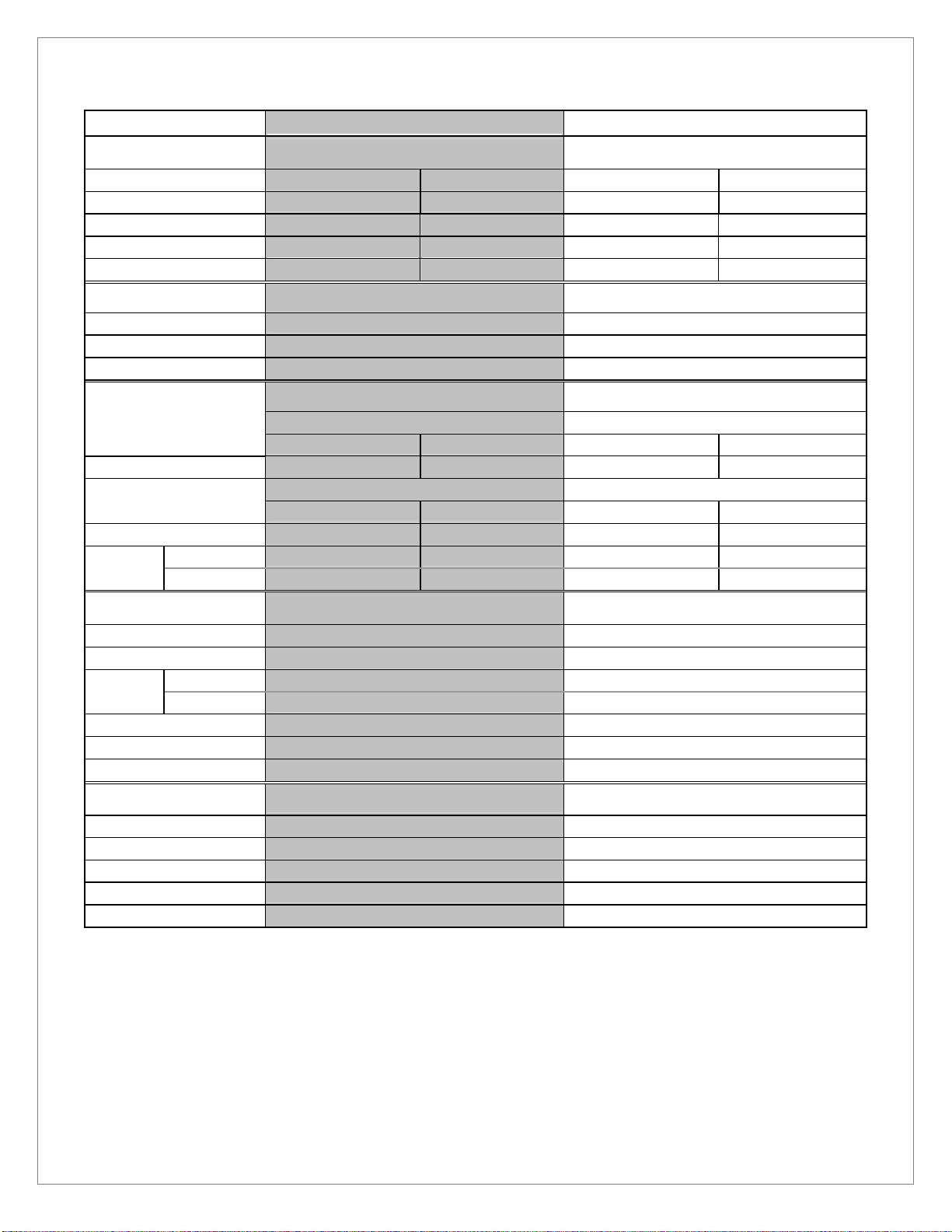
1 Specifications
Model Name
TVQ
-
EXA08
9K TVQ
-
EXA029K
General
Application
Refrigerant
Cooling Capacity
Discharge Air
Evaporator Temperature
Medium Temperature Frozen Food Medium Temperature Frozen Food
R-404A R-404A R-404A R-404A
380 BTU/h/ft. (892W) 482 BTU/h/ft. (1130W) 380 BTU/h/ft. (1338W)
24°F (-4.5°C)
19°F (-7.2°C) -20°F (-28.9°C) 19°F (-7.2°C) -20°F (-28.9°C)
-12°F (-24.4°C)
482 BTU/h/ft. (1695W)
24°F (-4.5°C) -12°F (-24.4°C)
Defrost (electric)
Frequency (hr) 12 12
Temp Term (°F) 50 50
Failsafe (min) 30 30
Electrical
Defrost Heater 3600 17.31 5400 25.96
Anti-condensation Heater 158.2 1.32 227.8 1.90
Fan
Motor
Standard
High Efficiency
Components
Defrost Heater
Anti-condensation Heater
Fan
Motor
Fan Blade Pitch
Pipe Diameter
Refrigerant Type
Standard
High Efficiency
Medium Temperature & Frozen Food Medium Temperature & Frozen Food
Medium Temperature & Frozen Food Medium Temperature & Frozen Food
1-phase 208V 1-phase 208V
(W) (A) (W) (A)
1-phase 120V 1-phase 120V
(W) (A) (W) (A)
92 1.36 138 2.04
22 0.44 33 0.66
Medium Temperature & Frozen Food Medium Temperature & Frozen Food
1-phase 208V 3600W 1-phase 208V 5400W
1-phase 120V 158.2W 1-phase 120V 227.8W
SPFBC51 x 4 SPFBC51 x 6
SSC2B12BRHBV1 x 4 SSC2B12BRHBV1 x 6
#126×4 #126×6
Liquid ⅜” Suction ¾” Liquid ⅜” Suction ¾”
R-404A R-404A
Measurements
Standard Ambient Conditions : Indoor temperature 75°F (24°C), relative humidity 55%, wind speed under 39.4 fpm.
All specifications are based upon temperature, humidity, and wind speed values equal to or less than Standard Ambient Conditions.
Products described in this manual are designed for indoor use only. Products should not be exposed to direct sunlight.
Fan motors are available in standard-type (AC fan motors) or high-efficiency type (DC fan motors).
Outer Dimensions
Display Area
Effective Capacity
Weight
Waste Outlet Dimensions
Medium Temperature & Frozen Food Medium Temperature & Frozen Food
35 ½” (H) × 70 ⅞” (W) × 96 ⅜” (L) 35 ½” (H) × 70 ⅞” (W) × 144 ⅝” (L)
38.8 sq.ft. 58.0 sq.ft.
47.0 cu.ft. 70.5 cu.ft
816 lbs 1213 lbs
1 ½” 1 ½”
4
Page 5
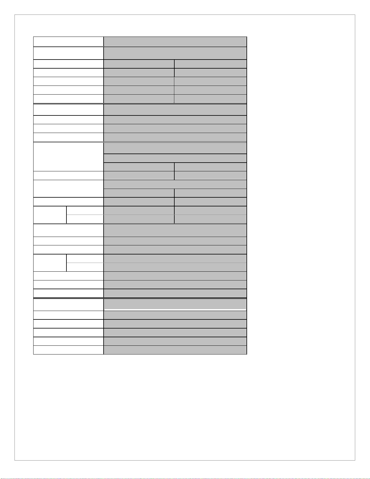
Model Na
me TVQ
-
EXA
CK
General
Applications Medium Temperature Frozen Food
Refrigerant R-404A R-404A
Cooling Capacity 1194 BTU/h/case (350W) 1501 BTU/h/case (440W)
Discharge Air 24°F (-4.5°C) -12°F (-24.4°C)
Evaporator Temperature 19°F (-7.2°C) -20°F (-28.9°C)
Defrost (electric)
Frequency (hr) 12
Temp Term (°F) 50
Failsafe (min) 30
Electrical
Defrost Heater 1445 6.95
1 phase 120V
(W) (A)
Anti-condensation Heater 82 0.68
Fan Motor
Standard
High Efficiency
Components
Defrost Heater 1-phase 208V 1445W
Anti-condensation Heater 1-phase 120V 82.0W
Standard
High Efficiency
Fan Blade Pitch
Pipe Diameter Liquid Pipe ⅜” Suction Pipe ¾”
Refrigerant Type
Medium Temperature & Frozen Food
Medium Temperature & Frozen Food
1 phase 208V
(W) (A)
23 0.34
5.5 0.11
Medium Temperature & Frozen Food
SPFBC51 x 1 Fan Motor
SSC2B12BRHBV1 x 1
#109×1
R-404A
Measurements
Outer Dimensions 35 ½” (H)× 37 ¼” (W) × 70 ⅞” (L)
Display Area 12.8 sq.ft.
Effective Capacity 15.6 cu.ft.
Weight 397 lbs
Waste Outlet Dimensions 1 ½”
Standard Ambient Conditions : Indoor temperature 75°F (24°C), relative humidity 55%, wind speed under 39.4 fpm.
All specifications are based upon temperature, humidity, and wind speed values equal to or less than Standard Ambient Conditions.
Products described in this manual are designed for indoor use only. Products should not be exposed to direct sunlight.
Fan motors are available in standard-type (AC fan motors) or high-efficiency type (DC fan motors).
Medium Temperature & Frozen Food
5
Page 6
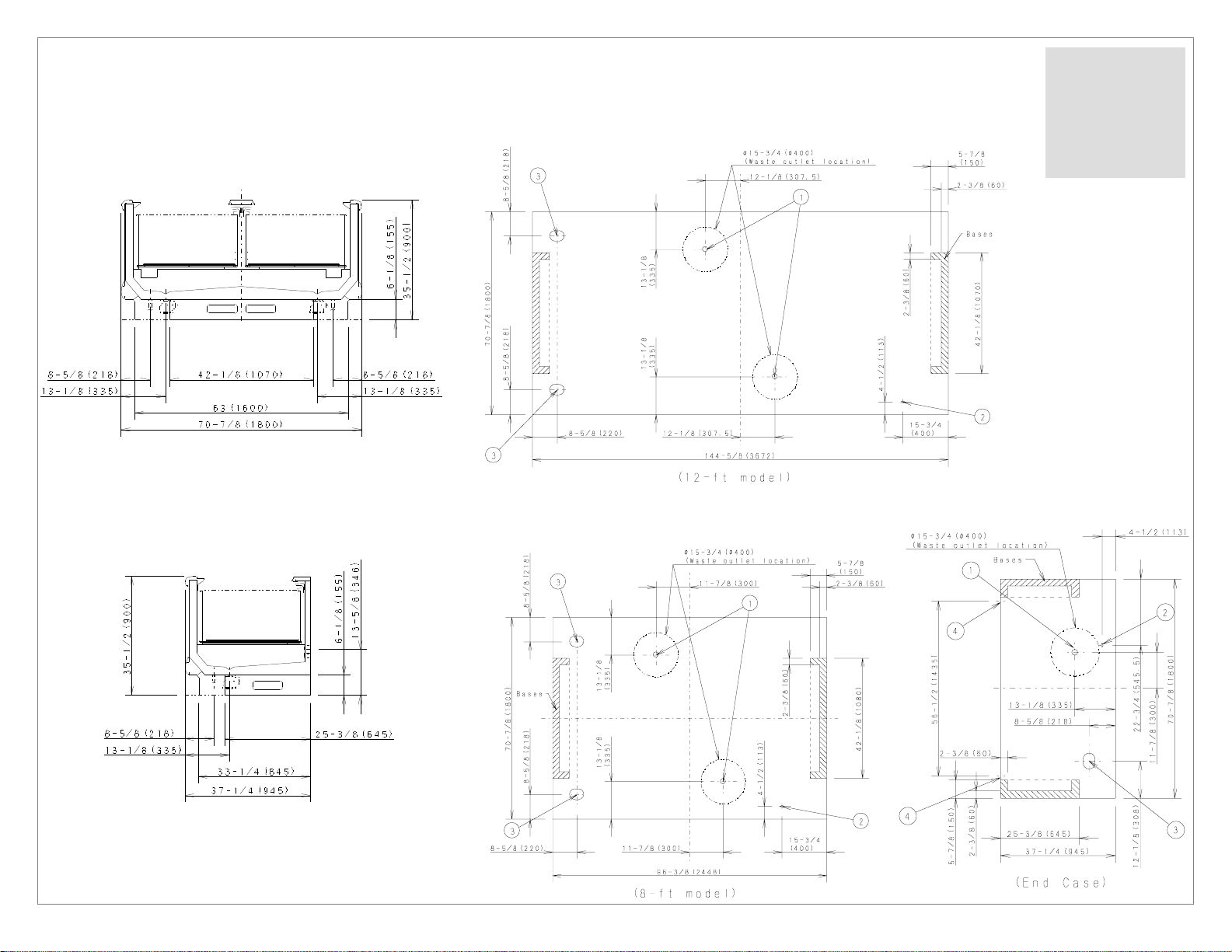
2 Dimensions
2.1 External Dimensions
(8-, 12-ft models)
* Dimensions given in inches and millimeters (mm in parentheses).
2.2 Footprint
① Waste Outlet
② Electrical Field
Connection
③ Refrigeration
Outlet
(End Case)
6
Page 7
3 Unloading and Carpentry Procedures
3.1 NSF Certification
The merchandisers described in this manual are built to meet the requirements of American National Standard/NSF International
Standard 7. Each merchandiser bears a nameplate identifying the type of application for which it was certified:
Type I display refrigerator / freezer: Intended for use in an area where the environmental conditions are controlled and maintained
so that the ambient temperature typically does not exceed 75°F.
3.2 Location
As noted above, the merchandisers described in this manual are design for the display of products in interior spaces with climate
control, with ambient conditions typically maintained below 75°F and 55% relative humidity. Proper merchandiser performance
cannot be guaranteed when ambient temperature and/or humidity exceeds this level.
Merchandisers should not be exposed to direct sunlight or other sources of heat.
Merchandisers should not be exposed to strong air currents, as these may disrupt the air curtain used to maintain proper
temperature inside the merchandiser display area.
3.3 Shipping Damage
All equipment should be examined for shipping damage prior to and during offloading. All equipment goes through outgoing
inspection upon leaving our warehouse, and the carrier assumes responsibility for the safe arrival of our merchandisers.
APPARENT DAMAGE: Any obvious loss or damage should be noted immediately at the time of receipt on the freight bill or
express receipt and signed by the carrier’s agent. Failure to do so may lead to rejection of the claim by the carrier.
CONCEALED DAMAGE: If damage that is not apparent during unloading is found after unpacking, retain all packing materials and
submit a written request to the carrier for inspection within 15 days.
LOST ITEMS: Any claims related to lost or missing items must be made to SANYO Commercial Solutions within 48 hours of
receipt of equipment.
3.4 Unloading Instructions & Precautions
WARNING
Cases are heavy and bulky, and require at least two people for unloading, moving, and installation.
8-ft and 12-ft merchandisers have wooden beams mounted on each side (no beams on end cases). Do not remove the wooden
beam from the bottom edges of each case until the cases have been moved into place in the store lineup.
Do not walk on the top of the merchandisers. Walking on the top of the merchandiser may lead to serious injury and/or damage
to the merchandiser. Do not place other heavy loads on the top of the merchandiser.
Recommended Practices for Unloading Merchandisers:
1. Use a J-bar (Johnson bar) to lift one end of the merchandiser.
2. Insert one or more dollies under the base leg.
3. Lift the other side with the J-bar.
4. (Optional) Insert one or more dollies.
5. Move merchandiser out of container.
6. Use dollies on both ends of the merchandiser to move to lineup location after unloading from container.
7
Page 8
3.5 Aligning Cases
WARNING
Cases are heavy and bulky, and require at least two people for unloading, moving, and installation.
Do not walk on the top of the merchandisers. Walking on the top of the merchandiser may lead to serious injury and/or damage
to the merchandiser. Do not place other heavy loads on the top of the merchandiser.
1. Review layout drawings for spaces where merchandisers are to be installed.
2. Based on the layout drawings and the merchandiser footprint drawings, mark the floor to indicate the exact locations of the
base legs (back edge and front edge) on each merchandiser. Multiple merchandisers should be aligned based upon the
position of the base legs.
3. Snap chalk lines for the front and rear positions of the legs on each row of merchandisers.
4. Mark the location showing the outside edge of each base leg on each merchandiser.
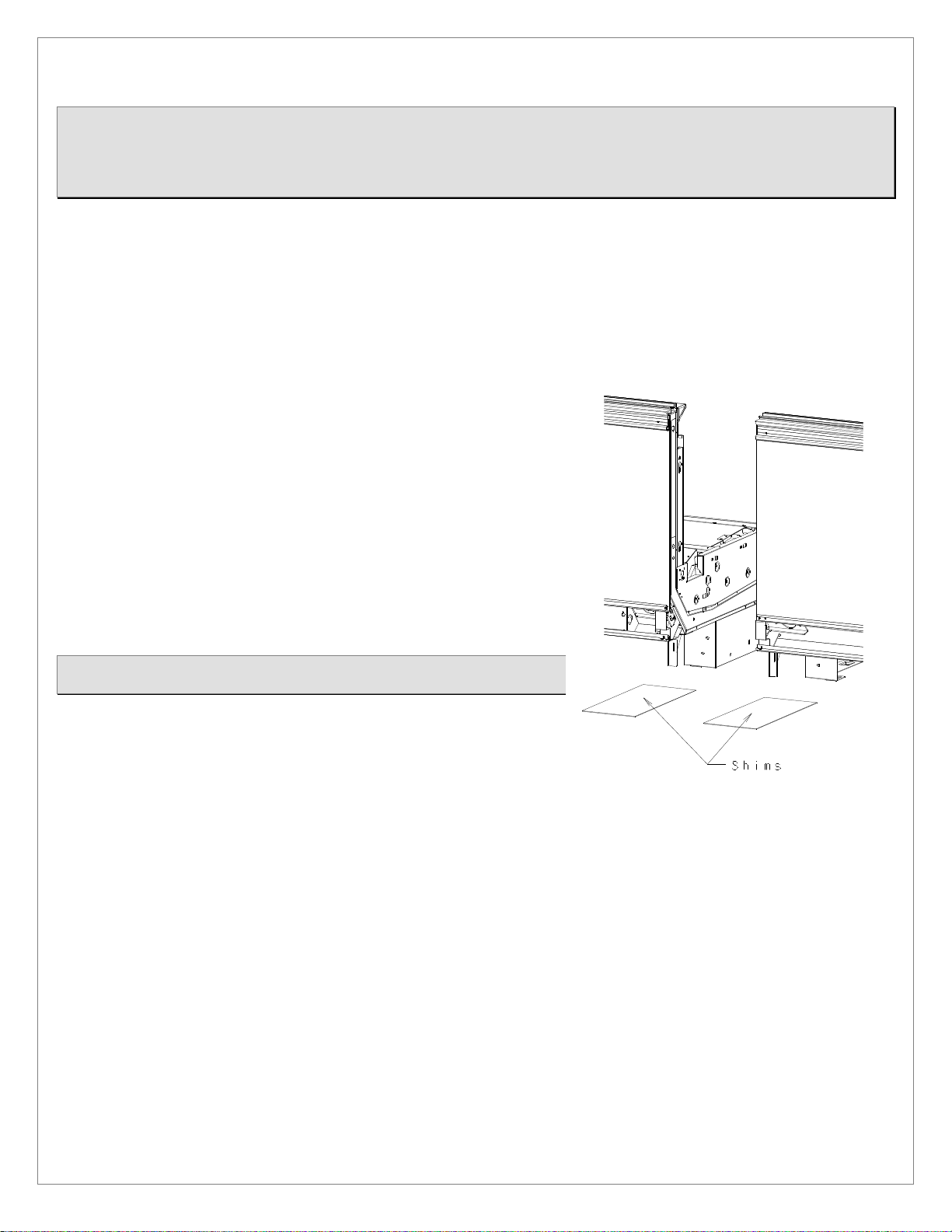
3.6 Case Leveling
Merchandisers must be installed level in order to ensure proper performance
and drainage.
1. For each lineup of cases to be joined, use a level (preferably a laser level)
to find the highest point on the front and rear chalk lines marked in step 3
above (during Case Alignment).
2. Determine which of the two points marked on the line is higher. This is
the highest point in the case lineup.
3. Estimate the number of shims needed for the four corners of each case
position, in order to bring all positions to the same height as the highest
point found in step 2.
4. For each row, place the first merchandiser case where it will sit over the
highest point in the lineup. Ensure that the case is level, using shims as
needed.
NOTE: Each base leg should rest on solid supports. Insert shims as needed if
there are any gaps between the floor and each base leg.
5. Continue placing cases in the lineup, working outward to both sides from
the position of the first case placed. Use shims to ensure that all cases in
the lineup are level.
8
Page 9

3.7 Joining Instructions
3.7.1 Applying gasket (for connecting cases or installing side panels).
①
Make sure that all merchandisers are resting level.
②
Make sure that all required parts for joining are present (gasket, bolts, joint covers, nuts, etc.).
③
Remove wire racks, deck pans, and air grilles from the far right and left ends of each case being joined.
④
Place gasket along the areas shown in bold in the drawing at right. When connecting two cases, apply gasket to one
case only.
Perimeter gasket is required by NSF.
Do not stretch or twist gasket when applying.
Do not leave gaps. Always overlap gasket rather than leaving gaps.
Gasket ends that are open must be sealed off by applying silicone at the installation site.
Insufficient or improper sealing may lead to insufficient cooling and condensation.
Gasket
9
Page 10

3.7.2 Connecting cases (8-ft and 12-ft cases)
: Gasket ends that are open must be sealed off
① Apply gasket as described above.
② Connect cases by using the attached bolts,
joint covers, nuts and caps.
Note: Connection points must be
silicone sealed.
Note
by applying silicone at the installation site.
10
Page 11

3.7.3 Connecting cases (End cases)
Note: Gasket ends that are open must be
sealed off by applying silicone at the
① Apply gasket as shown at right.
② Partially set M8 bolts in place at the four positions
shown at right, insert through connecting holes in the sides
of 8-ft or 12-ft wide island cases, then set firmly in place
from the 8-ft/ 12-ft unit side.
③ Fix the end case in position with the M8 bolts.
④ Fix the hand rail joints in place.
⑤ Fix the bumper joints in place.
Gasket
installation site.
11
Page 12

3.8 Installing side panels
Note: Gasket ends that are open must be
① Apply gasket as indicated below.
② Temporarily fix the side panel in place
with M8 bolts as indicated (see right). Pass
bolts through connection holes in the sides
of the 8-ft/ 12-ft wide island cases, then
finish fixing the bolts in place from the 8-ft/
12-ft case side.
③ Fix in place with screws as indicated (see
right).
④ Apply foam plugs to bolts.
⑤ Attach side panel caps.
12
sealed off by applying silicone at
the installation site.
Page 13

3.9 Installing Kickplate
13
Page 14

3.10 Installing handrail and bumper
Handrail
Handrail
Attaching the Bumper
1. Attach Maintenance Bumper (length 39-3/8 inches) to bumper brackets over the electrical connection box
(“raceway”) on each merchandiser. The raceway is located on the right end of each merchandiser.
2. Attach Full-Length Bumpers between Maintenance Bumpers on separate merchandisers, and also between
Maintenance Bumpers and patch ends.
* Cut Full-Length Bumpers to size on-site. Cut to correct size so that no gaps remain between pieces.
Attaching the Handrail
1. Starting at one end of merchandiser line-up, attach pieces of Handrail to handrail retainer, butting the pieces
end-to-end without gaps.
2. When you reach the final piece of Handrail to be installed between the last merchandiser in the line-up and
the patch end, cut that piece to length so there are no gaps between handrails or between handrails and
patch ends.
14
Page 15

4 Refrigeration, Plumbing & Electrical Procedures
4.1 Piping (Plumbing, Refrigeration)
● U-trap installation
Install U-trap referring to the drawing below.
● Sealing the refrigerant pipe opening
Seal pipe completely.
Insufficient sealing may cause the following problems:
• Insufficient cooling
• Excessive frost
• Icing over
• Condensation on the bottom of case.
Part Name Part Number
①
Drain Screen 845-0-1962-001-00
②
O-Ring 845-2-6946-001-00
③
Drain Trap Socket 845-2-6959-003-00
④
Drain Trap 845-2-1437-103-00
⑤
O-Ring 845-2-0183-107-00
⑥
Drain Cap 845-2-1345-110-00
15
Page 16

4.2 Electrical Data
Please refer to Specifications section and nameplate attached to merchandiser for electrical information.
4.3 Electrical – Guidelines & Precautions
All wiring and electrical field work must comply with the National Electrical Code (“NEC”) and other applicable local codes. All
electrical connections must be made inside the raceway area.
4.4 Wiring
4.4.1 Wiring Color Code
16
Page 17

4.4.2 Wiring diagram - 8-ft and 12-ft cases
17
Page 18

4.4.3 Wiring diagram - end cases
18
Page 19

5 Operation
5.1 Load Limits
In order to maintain proper temperature and unit performance, the air curtain in each merchandiser must remain unobstructed:
• Do not stock shelves beyond the marked load limits.
• Do not block discharge or return air grilles.
• Do not block airflow in any other way (with signs, tools, packages, etc.)
Failure to follow these precautions will lead to insufficient temperature control, spoilage of stored merchandise, and excessive
frost.
19
Page 20

5.2 Installing FDA/NSF Thermometer
Magnet
The suggested locations for the thermometers required by NSF/ANSI 7 and the FDA Food Code are
indicated above. It is the responsibility of the purchaser/end user of this product to determine the
locations within the food storage area that best meet these code requirements .
20
Page 21

6 Care and Cleaning Guidelines
In order to keep merchandisers sanitary and in good working order, we recommend thorough periodic cleaning as follows:
6.1 Daily Cleaning
6.1.1 Exterior Panels
a. Exterior panels should be cleaned with water only. Wet a soft cloth and wring it out to wipe down panels.
b. If required, you may use a mild detergent and warm water to remove stains. You should follow by wiping down with
water only in order to prevent discoloration.
c. Take particular care to clean areas that may be exposed to salt or saline solutions.
d. DO NOT use scrapers, blades or other sharp objects to remove adhesive, as you may damage panels. You may use
rubbing alcohol to remove adhesive if water and mild detergents alone are insufficient.
6.2 Monthly Cleaning
WARNING:
•
Make sure to turn merchandiser power off and close hand valve before cleaning deck pans or drain trap.
•
Take care not to touch the fans or wiring.
•
Use gloves.
Failure to take these precautions may lead to electric shock and accidents with fan blades.
You should turn power on and open hand valve ONLY AFTER you have completed cleaning and put parts back in place.
6.2.1 Deck Pan
Clean the entire deck pan surface, preferably with water only. If required, you may use a mild
detergent and warm water to remove stains. You should follow by wiping down with water only in
order to prevent discoloration.
6.2.2 Drain Trap
Check
and clean the drain trap at least once a month.
You may access the drain trap by removing the deck pans. Remove any material that has gathered in the drain trap and dispose
of it. Clean the drain trap and put it back in its original position.
21
Page 22

7 Service
7.1 Replacing Fan Motors and Blades
To replace the fan motors:
① Unplug the fan motor harness and remove socket covers.
② Push fan motor harness through hole in plenum.
③ Detach fan motor mounting bracket from plenum and pull up to remove.
22
Page 23

Fan Motor Assembly Part Codes (Standard-Type Fan Motors)
① Cap nut
②-a Vibration-damping washer
②-b Vibration-damping washer
②-c Fan motor
⑤ Bracket
For models with standard-type (AC) fan motors:
③ Fan blade
④ Motor mount
No. Part Name Model Part Code
①
②-a
②-b
②-c
③
④ Motor mount - 9FL-2-8140-001-00 6 4 1
⑤ Bracket - 9FL-2-1750-008-01 12 8 2
Cap nut - 9FL-2-6450-001-00 6 4 1
Fan motor SPFBC51 8FC-4-M140-000-30 6 4 1
#126 9FL-2-4230-004-00 6 4 -
Fan blade
#109 9FL-2-4230-005-00 - - 1
TVQ-EXA029K TVQ-EXA089K TVQ-EXACK
Quantity used Quantity used Quantity used
23
Page 24

Fan Motor Assembly Part Codes (High-Efficiency-Type Fan Motors)
① Cap nut
②-a Vibration-damping washer
③ Fan blade
②-b Fan motor
④ Bracket
For models with high-efficiency-type (DC) fan motors:
No. Part Name Model Part Code
①
②-a
②-b
③
④ Bracket - 9FL-2-1750-018-01 12 8 2
Cap nut - 9FL-2-6450-001-00 6 4 1
Fan motor
Fan blade
SSC2B12BRHBV1
#126 9FL-2-4230-004-00 6 4 -
#109 9FL-2-4230-005-00 - - 1
8FC-4-M100-000-30 6 4 1
TVQ-EXA029K TVQ-EXA089K TVQ-EXACK
Quantity used Quantity used Quantity used
24
Page 25

7.2 Replacing Heaters
Heater Part Codes
No Part Name Part Code
8FC-4-H110-000-30 2 - -
①
④
⑤
Defrost Heater
Drain Heater
Exterior
Anti-Condensation
Heater (Front)
Exterior
Anti-Condensation
Heater (Rear)
Interior
Anti-Condensation
Heater
8FC-4-H110-000-10 - 2 -
8FC-4-H110-000-50 - - 1
8FC-4-H110-000-40 2 - -
8FC-4-H110-000-20 - 2 - ②
8FC-4-H110-000-60 - - 1
8FC-4-H120-000-40 1 - -
8FC-4-H120-000-10 - 1 - ③
8FC-4-H120-000-70 - - 1
8FC-4-H120-000-50 1 - -
8FC-4-H120-000-20 - 1 -
8FC-4-H120-000-60 1 - -
8FC-4-H120-000-30 - 1 -
8FC-4-H120-000-80 - - 1
TVQ-EXA029K TVQ-EXA089K TVQ-EXACK
Quantity used Quantity used Quantity used
25
Page 26

26
Page 27

27
Page 28

WIMN 001.04
July 2008
 Loading...