

Page 1
Save These Instructions!
This air conditioner uses the new refrigerant R410A.
SEMI-CONCEALED CEILING-MOUNTED WALL-MOUNTED CONCEALED-DUCT
(4-WAY)
XHX1252
XHX1852
XHX2452
XHX3652
(1-WAY)
AHX0752
AHX0952
AHX1252
THX1252
THX1852
THX2452
Split System Air Conditioner
Remote Controllers
Timer Wired Remote Controller RCS-TM80BG
Wireless Remote Controller (for U, D type) RCS-BH80AAB.WL
Wireless Remote Controller (for X type) RCS-SH80AAB.WL
Wireless Remote Controller (for A, T type) RCS-TRP80AAB.WL
Wireless Remote Controller (for K type) RCS-SH1AAB
* Timer Wired Remote Controller comes with Instruction Manual.
KHX0752
KHX0952
KHX1252
KHX1852
KHX2452
(Standard Static Pressure)
UHX0752
UHX1252
UHX1852
UHX2452
UHX3652
(High Static Pressure)
DHX3652
DHX4852
• INSTRUCTION MANUAL
Pub. OI-85464189837000
© SANYO 2006
SANYO Electric Co., Ltd.
Gunma, Japan
Page 2
Contents
Product Information.......................................................................................................................2
Alert Symbols ................................................................................................................................2
Installation Location.......................................................................................................................3
Electrical Requirements ................................................................................................................3
Safety Instructions.........................................................................................................................3
Wireless Remote Control Unit (Optional parts) .............................................................................4
Parts Name and Functions ......................................................................................................4
Receiver...................................................................................................................................7
Operation.................................................................................................................................8
Using the Wireless Remote Control Unit .................................................................................9
Address Settings....................................................................................................................10
Emergency Operation............................................................................................................12
Troubleshooting .....................................................................................................................14
Adjusting the Airflow Direction.....................................................................................................15
Adjusting the Airflow Direction for Multiple Indoor Units Using a Single Remote Control Unit....17
Special Remarks .........................................................................................................................17
Setting the Timer.........................................................................................................................18
Page
Product Information
If you have problems or questions concerning your Air Conditioner, you will need the following
information. Model and serial numbers are on the nameplate on the bottom of the cabinet.
Model No. _________________________________ Serial No. _______________________
Date of purchase______________________________________________________________
Dealer’s address ______________________________________________________________
Phone number ___________________
Alert Symbols
The following symbols used in this manual, alert you to potentially dangerous conditions
to users, service personnel or the appliance:
This symbol refers to a hazard or unsafe practice
which can result in severe personal injury or
death.
This symbol refers to a hazard or unsafe practice
which can result in personal injury or product or
property damage.
2
OI-837-2-EG
Page 3
Installation Location
• We recommend that this air conditioner be installed properly by qualified installation
technicians in accordance with the Installation Instructions provided with the unit.
• Before installation, check that the voltage of the electric supply in your home or office is the
same as the voltage shown on the nameplate.
• Do not install this air conditioner where there are fumes or flammable gases, or in an
extremely humid space such as a greenhouse.
• Do not install the air conditioner where excessively high heat-generating objects
are placed.
Avoid: To protect the air conditioner from heavy corrosion, avoid installing the outdoor unit where
salty sea water can splash directly onto it or in sulphurous air near a spa.
Electrical Requirements
1. All wiring must conform to the local electrical codes. Consult your dealer or a qualified
electrician for details.
2. Each unit must be properly grounded with a ground (or earth) wire or through the supply
wiring.
3. Wiring must be done by a qualified electrician.
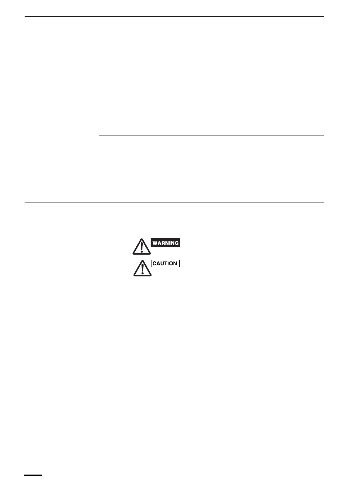
To warm up the system, the power mains must be turned on
at least five (5) hours before operation. Leave the power
mains ON unless you will not be using this appliance for an
extended period.
Power mains
ON
Safety Instructions
• Read this Instruction Manual carefully before using this air conditioner. If you still have
any difficulties or problems, consult your dealer for help.
• This air conditioner is designed to give you comfortable room conditions. Use this only
for its intended purpose as described in this Instruction Manual.
• Never touch the unit with wet hands.
• Never use or store gasoline or other flammable vapor or liquid near the air
conditioner — it is very dangerous.
• This air conditioner has no ventilator for intaking fresh air from outdoors. You must
open doors or windows frequently when you use gas or oil heating appliances in
the same room, which consume a lot of oxygen from the air. Otherwise there is a
risk of suffocation in an extreme case.
• Do not turn the air conditioner on and off from the power mains switch. Use the ON/
OFF operation button.
• Do not stick anything into the air outlet of the outdoor unit. This is dangerous
because the fan is rotating at high speed.
• Do not let children play with the air conditioner.
• Do not cool or heat the room too much if babies or invalids are present.
OI-837-3-EG
3
Page 4
Wireless Remote Control Unit (Optional parts)
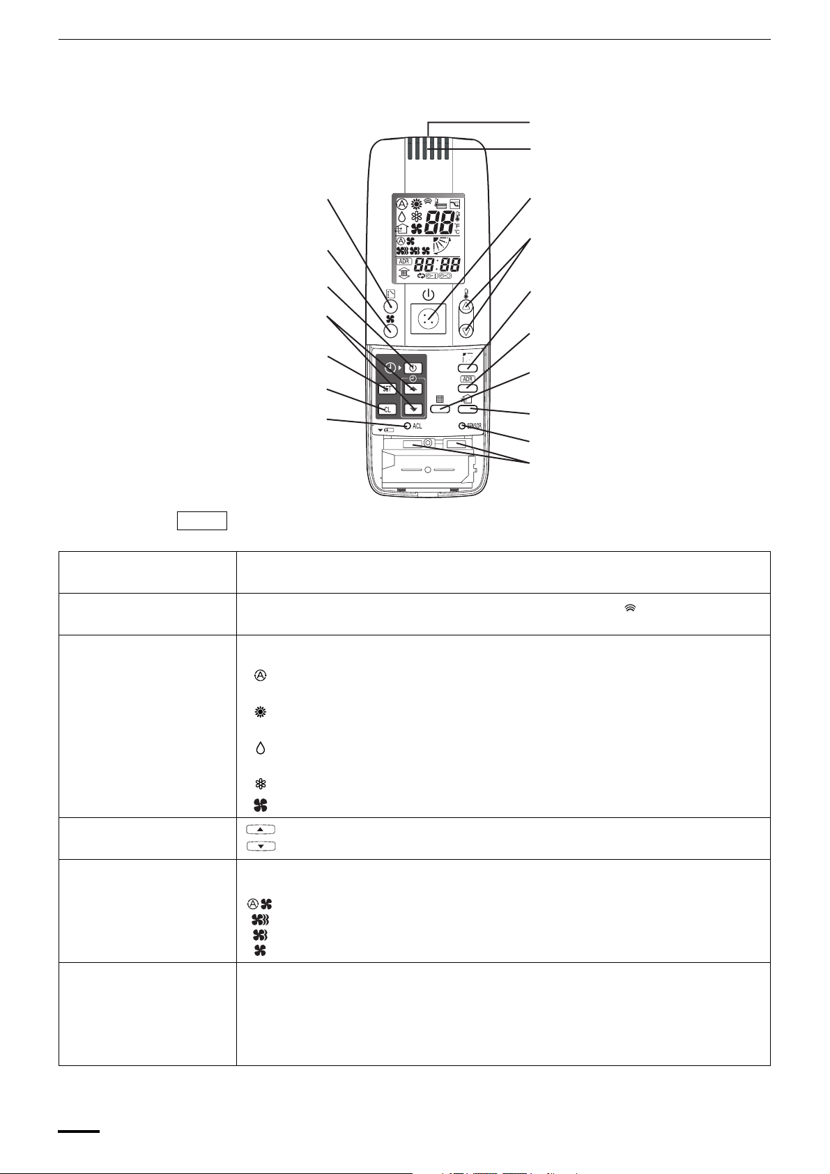
Parts Name and Functions
B: Transmitter
O: Remote control sensor
E: FAN SPEED selector button
J: TIMER SET button
K: Time setting buttons
NOTE
A: ON/OFF operation
button
C: MODE button
L: SET button
M: CL button
P: ACL button
(ALL CLEAR)
The illustration above pictures the wireless remote control unit after the cover has been
lowered and removed.
This button is for turning the air conditioner on and off.
A: ON/OFF operation button
D: Temperature setting buttons
I: FLAP button
G: ADDRESS button
F: FILTER button
N: VENTILATION button
H: A/C SENSOR button
Q: Slide switch
B: Transmitter When you press the buttons on the wireless remote control unit, the mark appears in the
display to transmit the setting changes to the receiver in the air conditioner.
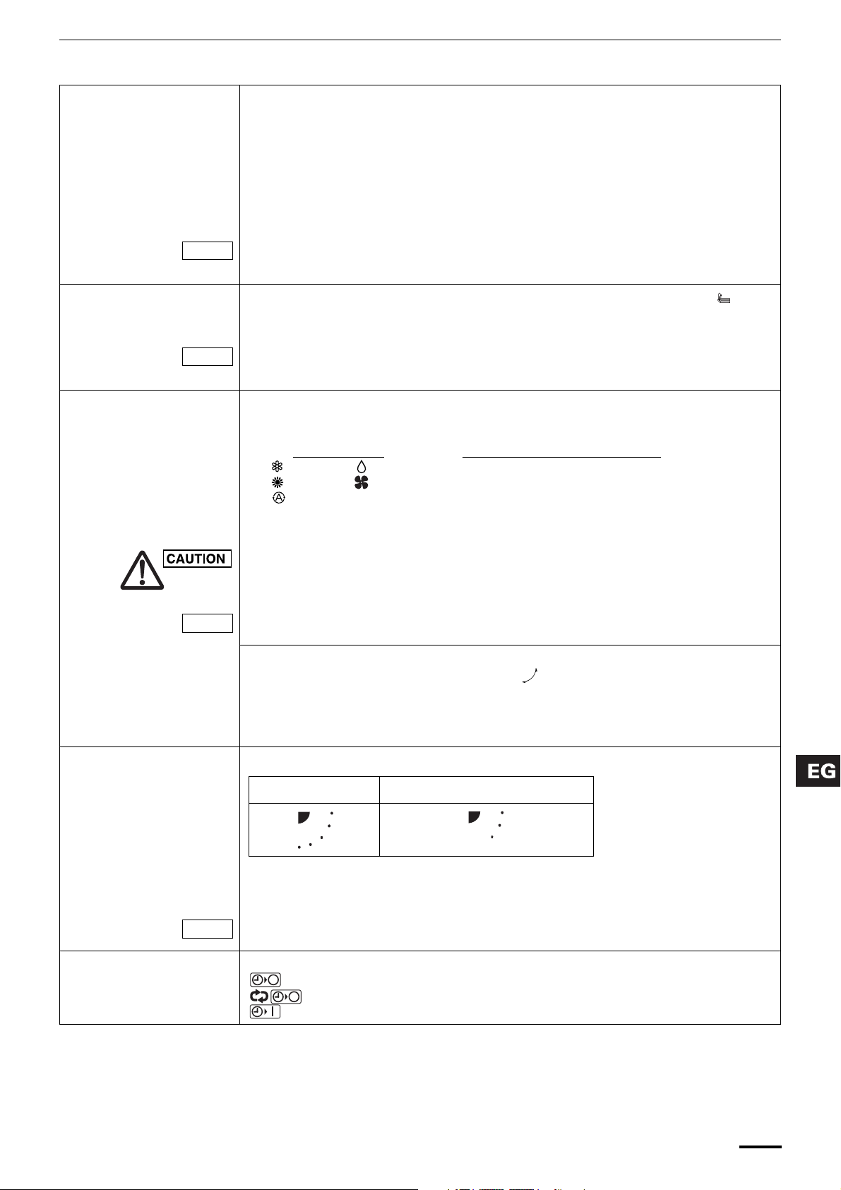
C: MODE button Use this button to select one of the following five operating modes.
(AUTO)
(HEAT) : Used for normal heating operation. Only for heat pump type
(DRY) : Used for dehumidifying without changing the room temperature.
(COOL) : Used for normal cooling operation. (temperature range: 64 to 86°F)
(FAN) : Used to run the fan only, without heating or cooling operation.
D: Temperature setting
buttons
E:
FAN SPEED selector
button
(AUTO)
(HI.)
(MED.)
(LO.)
F: FILTER button If a separately installed signal receiver is being employed, this button is used to turn off its
: Used to automatically set cooling or heating operation. Only for single heat pump type
(temperature range: 62 to 80°F)
(temperature range: 60 to 78°F)
(temperature range: 64 to 86°F)
: Press this button to increase the temperature setting.
: Press this button to decrease the temperature setting.
: The air conditioner automatically decides the fan speeds.
: High fan speed
: Medium fan speed
: Low fan speed
filter lamp. When the filter lamp has lighted, first clean the filter, and then press the FILTER
button to turn off the filter lamp.
When a wired remote control unit and wireless remote control unit are both used, the filter sign
on the wired remote control unit will be appeared. When this happens, first clean the filter, and
then press the FILTER button on one of the remote control units to turn off the filter sign.
4
OI-837-4-EG
Page 5
Parts Name and Functions (continued)
G: ADDRESS button When a multiple number of indoor units that can be operated by the wireless remote control
unit have been installed in the same room with a multi-unit or single-unit installation, this
button enables addresses to be set in order to prevent the sending of signals to the wrong
indoor unit. Each of up to six indoor units can be controlled separately using its own wireless
remote control unit by matching the number of the address switch on the operation area of the
indoor unit and the number used for the address of its remote control unit. (The indoor units
cannot be controlled separately when they are used in a flexible combination format,
simultaneous operation of multi units format or any other such format since they will all
operate at the same time.)
NOTE
H: A/C SENSOR button When you press this button (use a small-tipped object such as a ballpoint pen), the
NOTE
I: FLAP button 1. Use this button to set the airflow direction to a specific angle.
NOTE
(SWEEP) 2. Use this button to make the airflow direction sweep up and down automatically.
When the batteries are replaced, the address setting returns to “ALL”, and so please make the
setting again.
indication will disappear at the display. And the room temperature is detected by the sensor
which is built in the indoor unit and the air conditioner is controlled accordingly.
If the remote control is located near a heat source, such as a space heater or in direct
sunlight, press the A/C SENSOR button to switch to the sensor on the indoor unit.
The airflow direction is displayed on the remote control unit.
Operation mode
(COOL) or (DRY) 3
(HEAT) or (FAN) 5
(AUTO)
Cooling mode: 3
Heating mode: 5
• In the cool mode and dry mode, if the flaps are set in a downward position,
condensation may form and drip around the vent.
• Do not move the flap with your hands.
This function is available only for models X, A, T and K.
Number of airflow direction settings
Press this button several times until the symbol appears on the display.
NOTE
J: TIMER SET button
(OFF Timer)
(OFF Cycle Timer)
(ON Timer)
To stop the swing operation
Press the FLAP button again during the flap swing operation to stop the flap at the desired
position. Then, the airflow can be set from the top position by pressing the FLAP button again.
Indicator when swing operation is stopped
Fan and heating Cooling and drying
During cooling and drying, the flap does not stop at the downward position. Even if the flap is
stopped at the downward position during the swing operation, it does not stop until it moves to
the third position from the top.
This function is available only for models X, A, T and K.
Use this button while the unit is operating to switch between timer settings.
: The air conditioner stops after a preset time elapses.
:The air conditioner always stops after a preset time elapses.
: The air conditioner starts after a preset time elapses.
OI-837-5-EG
5
Page 6
Parts Name and Functions (continued)
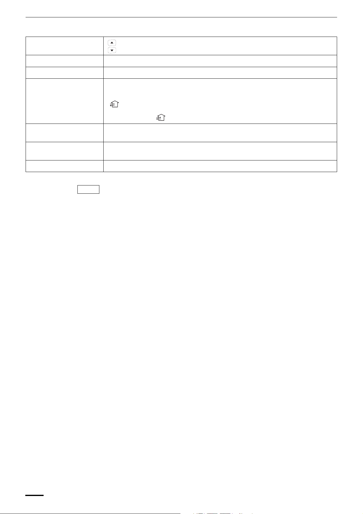
K: Time setting buttons : Press this button to increase the time.
: Press this button to decrease the time.
L: SET button Use this button to set the timer.
M: CL button Use this button to clear the timer setting.
N: VENTILATION button This is used when a ventilation fan (available commercially) is connected. Pressing the
VENTILATION button turns the fan on and off. The ventilation fan also turns on and off when
the air conditioner unit is turned on and off. (The display of the remote control unit shows
“ ” while the ventilation fan is running.)
* If the VENTILATION button is held down for 4 or more seconds when the batteries have
been replaced, “ ” appears on the display, and the ventilation fan can be used.
O: Remote control sensor This detects the temperature around the remote control unit when the remote control unit
position has been selected using the sensor button.
ACL button (ALL CLEAR)
P:
Q: Slide switch This switch is for setting the operation mode of the indoor unit and setting the flaps.
NOTE
Puts the wireless remote control unit into pre-operation status. This is used after the batteries
have been replaced or when the slide switch setting has been changed.
• The wireless remote control unit sends the temperature signal to the air conditioner
regularly at five-minute intervals. If the signal from the wireless remote control unit stops
for more than ten minutes due to the loss of the wireless remote control unit or other
trouble, the air conditioner will switch to the temperature sensor which is built into the
indoor unit and control the room temperature. In these cases, the temperature around the
wireless remote control unit may differ from the temperature detected at the air
conditioner’s position.
• When low fan speed is selected and the air conditioner is in cooling operation at a low
outdoor temperature of less than 50°F, the air conditioner may automatically switch to
medium fan speed to prevent freezing.
6
OI-837-6-EG
Page 7

Receiver
The signal receivers with the exception of the separately installed signal receiver are mounted
on the indoor units.
X type
K type
A: Receiver This section picks up infrared signals from the wireless remote control unit (transmitter).
Indication lamps One of these lamps will blink when trouble has occurred. When an indicator lamp starts to
blink, refer to “Troubleshooting” on page 14.
T type
Separately installed
signal receiver
(A, U, D type)
B: Operation lamp This lamp lights when the appliance is turned on.
C: Timer lamp This lamp lights when the system is being controlled by the timer.
D: Standby lamp • This lamp lights at the following times during heating operations:
When operation has started, when the thermostat has been activated, during a defrosting
operation
• The lamp blinks when trouble has occurred.
E: Emergency operation
button
F: ADDRESS switch This switch is used in order to prevent the sending of signals to the wrong indoor unit when a
G: SWING button When this button is pressed, the airflow sweeps up and down automatically.
H: FILTER lamp This lamp lights to indicate that it is time to clean the filter.
• If two beeps are heard, the operation lamp among the indication lamps has lighted and the timer lamp and standby
lamp blink alternately in cases where heat pump models are used, this indicates a cooling/heating mode
mismatch and, as such, operation in the desired mode cannot be performed. (The same beeps will be heard and
the same operation lamps will light when auto cooling/heating has been selected on a model which does not have
the auto cooling/heating function.)
• When local operation has been set to disable because the centralized control mode is established, for instance,
pressing the ON/OFF operation button, MODE button or temperature setting buttons results in the sounding of
five beeps, and the attempted change in the operation will not be accepted.
This is used when operation cannot be performed due to trouble with or loss of the wireless
remote control unit.
multiple number of indoor units that can be operated by the wireless remote control units have
been installed in the same room.
OI-837-7-EG
7
Page 8

Operation
STEP 2
STEP 3
STEP 1, 6
STEP 4
STEP 5
NOTE
• To warm up the system, the power mains must be turned on at least five (5) hours before operation.
STEP 1 To start the air conditioner: Press the operation button (ON/OFF button).
STEP 2 Setting the mode: Press the MODE button to select the mode of your choice.
[ (AUTO), (HEAT), (DRY), (COOL) or (FAN)]
STEP 3 Setting the fan speed: Press the FAN SPEED selector button to select the fan speed of your choice.
[ (AUTO), (HI.), (MED.) or (LO.)]
If AUTO is selected, the fan speed switches automatically.
STEP 4
Setting the temperature:
Use the or button as appropriate to change the temperature setting as desired.
( reduces the temperature, and increases the temperature.)
* The temperature cannot be set during FAN mode operation.
STEP 5 Setting the airflow direction: When more than one indoor unit is connected, the UNIT button is used first to
select a unit. Then use the FLAP button to set the airflow direction to a specific
angle or to sweep.
STEP 6 To stop the air conditioner: Press the operation button (ON/OFF button) again.
Automatic heating and
cooling
The air conditioner automatically performs heating and cooling operation based on the
difference between the temperature setting and room temperature. All indoor units in the
same refrigerant system can be operated with a single group control.
Simultaneous operation of
multiple units (Group
control)
Group control is suitable for air conditioning of a large room using multiple air conditioning
units.
• One remote control unit can control up to eight indoor units.
• All indoor units have the same settings except for the airflow direction.
• The temperature sensors at the indoor unit side are used.
Outdoor unit
Indoor unit
Remote control unit
8
Signal line
OI-837-8-EG
Page 9

Using the Wireless Remote Control Unit
Slide switch This is used to set the operation mode of the indoor units and to set the flaps.
• Depending on the indoor unit used, the operation display and airflow direction display
settings will differ as shown below.
• Use a pointed implement to change the switch position.
• When the switch position has been changed, press the ACL button.
* For details on the flap functions, refer to the operating instructions of the indoor unit used.
With the battery cover
removed
How to install
batteries
Model which supports
different flap settings
Slide switch position
Flap display on wireless
remote control unit
Heat pump (with auto
cooling/heating
function)
Operation mode display
on wireless remote
control unit
Slide switch position
Swing-only model No-flap model
Heat pump (without
auto cooling/heating
function)
Cooling only
• Before use, check that the slide switch has been set to the position shown in the figure
above. For details on how to set the slide switch, consult your dealer.
1. Slide the cover in the direction indicated by the arrow and
remove it.
2. Install two AAA alkaline batteries. Make sure the batteries
point in the direction marked in the battery compartment.
3. Use a pointed implement to press the ACL button.
• The batteries last about a year, depending on how much
you use the wireless remote control unit. Replace the
batteries when the wireless remote control unit’s display
fails to light, or when the remote control cannot be used to
change the air conditioner’s settings.
ACL
button
Cover
Cover
ACL
button
• When the batteries are to be replaced, make sure that both
batteries are new and that the same kind of battery is used.
• Remove the batteries if the wireless remote control unit is
not going to be used for a prolonged period.
• Dispose of the used batteries at the designated location.
OI-837-9-EG
How to use the
wireless remote
control unit
• Point the wireless remote control unit’s transmitter at the signal receiver. If the signal is
received properly, a beep is heard. (Two beeps are heard only when operation starts up.)
• Signals can be received over a distance of approximately 26 ft. This distance is
approximate: it may be slightly more or less depending on how much charge remains in the
batteries and on other factors.
• Ensure that the signals will not be blocked by any objects positioned between the
transmitter and signal receiver.
• Avoid placing the wireless remote control unit where it will be exposed to direct sunlight or in
the direct path of the air blown out from the air conditioner, near a heating appliance, etc.
• Do not drop, throw or wash the wireless remote control unit.
• Signal reception may not be accepted in rooms with fluorescent lights that use the
electronic instantaneous lighting system (rapid start system) or inverter system. For further
details, contact your dealer.
9
Page 10

Using the Wireless Remote Control Unit (continued)
When mounting the
wireless remote control
unit on a wall for use
Secure the installation fitting of the wireless
remote control unit using the screws.
Installation fitting of wireless remote control unit
Operating tips • Do not operate the wireless remote control unit too far away from the signal receiver.
• Before mounting the wireless remote control unit on the wall, place the unit at the mounting
position, press the ON/OFF operation button and check that the signals are received
properly.
• To remove the wireless remote control unit, disengage it by pulling it toward you.
Doing so may cause operational errors.
Make absolutely sure that the wireless remote control unit and signal receiver are both in
the same room.
• When operating the wireless remote control unit, point it directly at the signal
receiver.
A beep is heard when a signal is received properly.
• Avoid places where the wireless remote control unit will be obscured by curtains, etc.
Remove it before operation.
2
1
Press.
Place here.
Procedure for installing the
wireless remote control unit
How to check the
addresses
How to set the matching
address
Address Settings
When a multiple number of indoor units that can be operated by the wireless remote control unit
have been installed in the same room with a multi-unit or single-unit installation, this button enables
addresses to be set in order to prevent the sending of signals to the wrong indoor unit. Each of up to
six indoor units can be controlled separately using its own wireless remote control unit by matching
the number of the address switch on the operation area of the indoor unit and the number used for
the address of its wireless remote control unit. (The indoor units cannot be controlled separately
when they are used in a flexible combination format, simultaneous operation of multi units format or
any other such format since they will all operate at the same time.)
The signal receiver has an address switch for signal reception, and the wireless remote control unit
has an address switch for signal transmission.
When the ADDRESS button on the wireless remote control unit is pressed, the current address
appears on the wireless remote control unit’s display. The buzzer sounds if the address
displayed matches the signal receiver’s address. (The buzzer always sounds if “ALL” appears
as the address display.)
If “ALL” appears as the address display, operations can be performed irrespective of the signal
receiver’s address. Point the wireless remote control unit at the signal receiver of the unit to be
operated, and send the signal.
Wireless remote control unit’s address setting
1. When the ADDRESS button is held down for 4 or more seconds, “ ” lights on the
wireless remote control unit’s display, and the current address blinks.
2. Each time the ADDRESS button is now pressed, the address changes by one setting in the
following sequence: ALL → 1 → 2 → 3 ... → 6 → ALL.
Select the setting which matches the setting of the address switch in the operation area of
the indoor unit to be operated.
3. When the SET button is now pressed, the address stops blinking and lights instead, and it
remains on the display for 5 seconds.
The buzzer sounds if the setting matches the setting of the address switch in the operation
area of the indoor unit.
10
NOTE
When the batteries are replaced, the address setting returns to “ALL”.
OI-837-10-EG
Page 11

Wireless remote
control unit
address displays
Address Settings (continued)
……
X type
Position of
address switch on
signal receiver
(inside indoor unit)
T type
Position of
address switch on
signal receiver
(inside indoor unit)
K type
Position of
address switch
inside indoor unit
A, U, D type
Position of
address switch in
signal receiver
* The address switch
in the operation
area may be set to
any position.
* The address switch
in the operation
area may be set to
any position.
* The address switch
in the operation
area may be set to
any position.
* The address switch
in the operation
area may be set to
any position.
……
……
……
……
For positions 1, 2 and 3, set the
knob to the left; conversely, for 4, 5
and 6, set the knob to the right.
For positions 1, 2 and 3, set the
knob to the left; conversely, for 4, 5
and 6, set the knob to the right.
For positions 1, 2 and 3,set the
knob upward (1); conversely, for 4,
5 and 6, set the knob downward
(ON).
For positions 1, 2 and 3, set the
knob to the left; conversely, for 4, 5
and 6, set the knob to the right.
OI-837-11-EG
11
Page 12
Emergency Operation
In any of the following events, use the Emergency operation button to operate the air
conditioner on a makeshift basis.
• When there is no charge remaining in the wireless remote control unit’s batteries
• When the wireless remote control unit has failed
• When the wireless remote control unit has been lost or misplaced
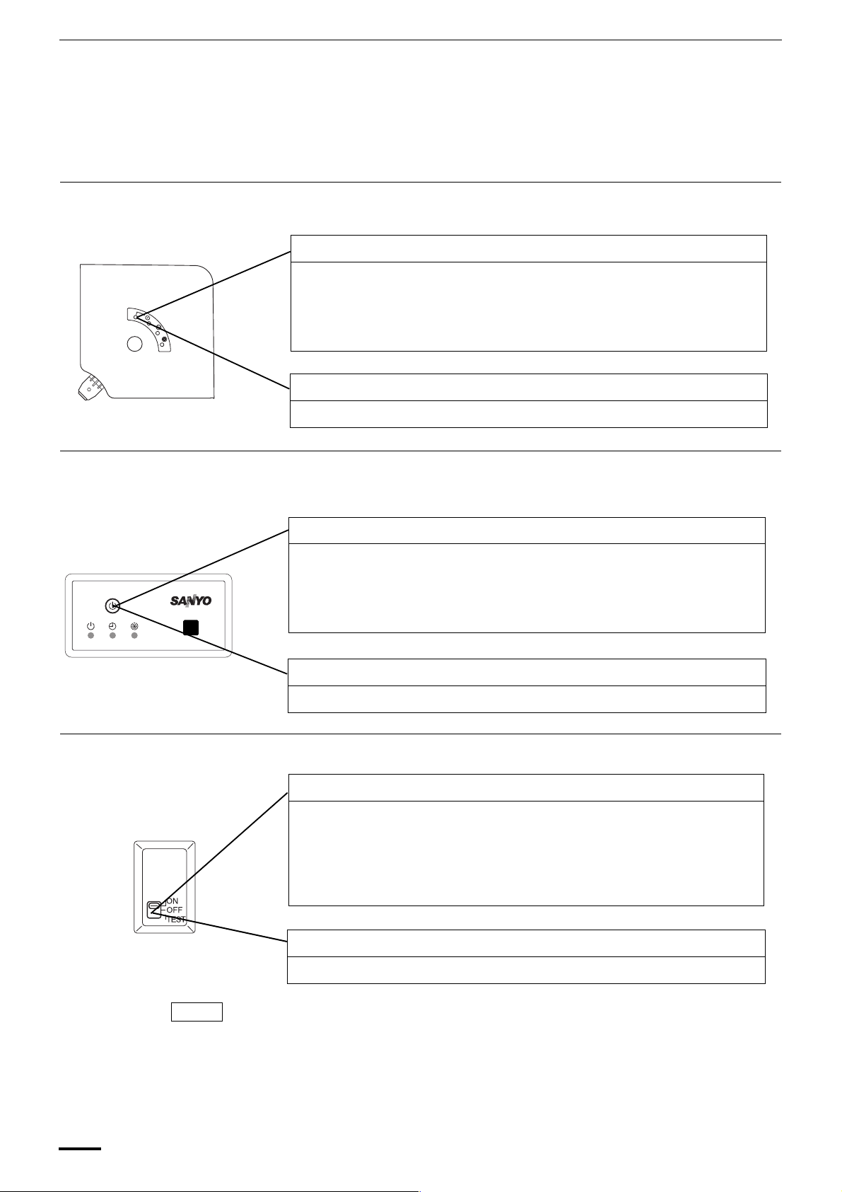
X type Initiate operation using the Emergency operation button in the operation area of the indoor unit.
Opeartion
Press the Emergency operation button.
The air conditioner initiates a cooling operation when its operation is started up at
a room temperature of 75°F or above.
Conversely, it initiates a heating operation when its operation is started up at a
room temperature below 75°F.
Shutdown
Press the Emergency operation button once more.
T type Initiate operation using the Emergency operation button in the signal receiver on the indoor
unit.
Opeartion
Press the Emergency operation button.
The air conditioner initiates a cooling operation when its operation is started up at
a room temperature of 75°F or above.
Conversely, it initiates a heating operation when its operation is started up at a
room temperature below 75°F.
Shutdown
Press the Emergency operation button once more.
K type Initiate operation using the Emergency operation button in the operation area of the indoor unit.
Opeartion
Set the ON/OFF operation switch to “OFF” first.
Then set it to “ON.”
If a heat pump is used, the air conditioner initiates a cooling operation when its
operation is started up at a room temperature of 75°F or above or it initiates a
heating operation when its operation is started up at a room temperature below
75°F.
12
NOTE
Shutdown
Set the ON/OFF operation switch to “OFF.”
• TEST is used to initiate a trial run when the air conditioner is first installed. It is not used
under normal circumstances.
• To restart the wireless remote control unit’s operation, the ON/OFF operation switch must
be set to ON without fail. If it is kept at the OFF setting, the signals from the wireless remote
control unit will not be accepted.
OI-837-12-EG
Page 13

Emergency Operation
A, U, D type Initiate operation using the Emergency operation button in the signal receiver.
1. Press the Emergency operation button.
The air conditioner initiates a cooling operation when its operation is started
up at a room temperature of 75°F or above.
Conversely, it initiates a heating operation when its operation is started up at a
room temperature below 75°F.
2. When the SWING button is pressed, the air direction is automatically switched
from upward to downward or vice versa.
Shutdown
Press the Emergency operation button once more.
(continued)
OI-837-13-EG
13
Page 14

Troubleshooting
Check out the following points before requesting service.
Trouble Possible Cause Remedy
The air conditioner
does not run even
Is the air conditioner in the shutdown mode or
was the switch operated after a power failure?
Press the wireless remote control unit’s
ON/OFF operation button again.
when the ON/OFF
operation switch has
been set to ON.
How about the local power switch? If it was off, set it now to on.
Have any of the fuses blown? If a fuse has blown, contact your dealer.
Is the ON timer operation mode established? Clear the timer operation.
If the signal receiver’s NORMAL/ALL OFF
switch set to “ALL OFF”?
If it is, set it to the “NORMAL” position and
cancel the operation.
Check again.
Have the wireless remote control unit’s
If they have, replace them with new ones.
batteries run down?
Do the indication lamps show a cooling/heating
Change the operation mode.
mismatch or is the auto cooling/heating
function not available?
Auto cooling/heating or heating appears on the display even though the air
conditioner is a cooling-only model.
Change the setting of the wireless remote
control unit’s slide switch. (See page 9)
Trouble Possible Cause
(An indicator lamp is blinking.) • Some kind of trouble has occurred in communication between the signal
Operation
Timer
Preparing for
operation
receiver and indoor unit. Alternatively, the wrong address has been set
when a wired remote control unit is used.
Operation
Operation
Operation
Operation
Contact your dealer.
Operation
Operation
Timer
Timer
Timer
Timer
Timer
Timer
Preparing for
operation
Preparing for
operation
Preparing for
operation
Preparing for
operation
Preparing for
operation
Preparing for
operation
• Some kind of trouble has occurred in communication between the indoor
unit and outdoor unit.
• The indoor unit’s protection device has been activated. Alternatively, the
auto flap connector of the ceiling panel has been disconnected.
• The outdoor unit’s protection device has been activated.
• Something is wrong with the temperature sensor.
• The outdoor unit’s compressor has been protected.
• A trial run is underway. Set the trial run switch to OFF.
If the trouble persists even after performing the checks recommended above, shut down the air conditioner’s operation, set the
local power switch to OFF, and contact your dealer with the model number and trouble symptoms. You must NOT attempt to
make repairs yourself due to the dangers involved. If one or more of the indication lamps is blinking, give this information to the
dealer as well.
14
OI-837-14-EG
Page 15

Adjusting the Airflow Direction
4-way (X) air conditioner is equipped with auto flaps.
You can set the airflow direction to a specific angle or to the sweep mode using the remote
control unit.
Do not move the flap with your hands.
4-way type (X) • The air outlet flap can be easily removed and washed with water.
• Be sure to always stop operation before removing the flap.
• After washing with water, allow it to dry, and then remount it with the arrow facing outward.
Ceiling mounted type (T)
A. Vertical directions (automatic)
This air conditioner is equipped with an auto flap. You can set the airflow direction to a specific
angle or to the sweep mode using the remote control unit. (Refer to the description of the
remote control unit.)
Zone ‘‘A’’
for cooling
30°
Zone ‘‘B’’ for
heating
Indoor unit
60°
Do not move the flap with your hands.
B. Horizontal directions (manual)
The horizontal airflow direction can be adjusted manually by moving the vertical vanes to the
left or right.
Wall mounted type (K)
A. Vertical directions (automatic)
Confirm that the remote control unit has been turned on. Press the FLAP button to start the flap
moving up and down. If you want to stop the flap movement and to direct the air in the desired
direction, press the FLAP button again. In the cool mode, don’t direct the flap down more than
30°, otherwise, condensation may drip on to the floor. Zone ‘‘A’’ is the recommended flap
position for cooling.
Do not move the flap with your hands.
B. Horizontal directions (manual)
The horizontal airflow direction can be adjusted manually by moving the vertical vanes to the
left or right.
OI-837-15-EG
15
Page 16

Adjusting the Airflow Direction (continued)
Semi-concealed type
1-way type (A)
Flap
This air conditioner is not equipped with
an auto flap. (Manual adjusting only)
Hold the flap and move it up and down to adjust the direction of the airflow.
When the flap moves, the line engraved on the rim of the disc will move up and down.
In the cool mode, manually adjust the angle of the flap so that the indicator is in line with the
blue rectangular mark on the label.
Otherwise, condensation may drip onto the floor.
In the heat mode, adjust the flap so that the indicator is in line with the red rectangular mark.
Concealed duct type (U, D)
This air conditioner is not equipped with air outlet parts. These must be obtained locally. Please
refer to the manual of the locally adopted air outlet parts.
Indicator
disc
Label
Indicator line
For cooling
(blue)
For heating (red)
16
OI-837-16-EG
Page 17

Adjusting the Airflow Direction for Multiple Indoor Units
Using a Single Remote Control Unit
• The airflow direction cannot be set using the remote control unit for the 1-way type (A) and
concealed duct type (D, U).
• If multiple indoor units are connected to a remote control unit, the airflow direction can be set for
each indoor unit by selecting the indoor units (see the operation below).
Auto Flap ( ) button
• To set the airflow for individual units, press the UNIT button. Display shows the indoor unit
number under group control. Set the airflow direction for the indoor unit that is shown on the
display.
• Each time UNIT is pressed, the indicator changes in the order shown below.
• When nothing is displayed, you can make the setting for all indoor units in one operation.
• The unit number is displayed as Outdoor Unit Number–Indoor Unit Number. It varies
depending on the number of units under group control.
One outdoor unit and eight indoor units Two outdoor units and four indoor units
No display
Î
ÎÎ
Unit No.
1–1
Unit No.
1–2
Unit No.
Î
1–3
Unit No.
1–8
Î
No
display
Unit
Unit
Î
ÎÎ Î
No.
1–1
No.
1–2
Unit
1–3
No.
Unit
No.
1–4
Î
Special Remarks
‘‘DRY’’ Operation
Unit
No.
2–1
Unit
No.
2–4
How it works • Once the room temperature reaches the level that was set, the unit repeats the cycle of
turning on and off automatically.
• In order to prevent the humidity in the room from rising again, the indoor fan also turns off
when the unit stops operating.
• The fan speed is set to ‘‘LO.’’ automatically, and cannot be adjusted.
• ‘‘DRY’’ operation is not possible if the outdoor temperature is 59°F or less.
Heating Operation
Heating performance • Because this appliance heats a room by utilizing the heat of the outside air (heat pump
system), the heating efficiency will fall off when the outdoor temperature is very low. If
sufficient heat cannot be obtained with this heat pump, use another heating appliance in
conjunction with this unit.
Defrosting • When the outdoor temperature is low, frost or ice may form on the outdoor heat exchanger
coil, reducing the heating performance. When this happens, a microcomputer-controlled
defrosting system operates. At the same time, the fan on the indoor unit stops (or runs at
very low speed in some cases) and the ‘‘STANDBY’’ indicator appears on the display until
defrosting is completed. Heating operation then restarts after several minutes. (This interval
will vary slightly depending upon the outdoor temperature and the way in which frost forms.)
(standby) on the
display
NOTE
• For several minutes after the start of heating operation, the indoor fan will not start running
(or it will run at very low speed in some cases) until the indoor heat exchanger coil has
warmed up sufficiently. This is because a cold draft prevention system is operating. During
this period, the ‘‘ ’’ (standby) indicator remains displayed.
• ‘‘ ’’ (standby) remains displayed during defrosting or when the compressor has been
turned off (or when the unit is running at very low speed) by the thermostat when the
system is in the heating mode.
• Upon completion of defrosting and when the compressor is turned on again, ‘‘ ’’
(standby) will turn off automatically as heating operation resumes.
Should the power fail while the unit is running
OI-837-17-EG
If the power supply for this unit is temporarily cut off, the unit will automatically resume
operation (once the power is restored) using the same settings before the power was cut off.
17
Page 18

Setting the Timer
Using the timer • Set the timer during air conditioner operation.
Recommended usage Display
To stop the air conditioner after a preset time
elapses
To always stop the air conditioner after a preset
time elapses
To start the air conditioner after a preset time
elapses
Time indicator of timer Each time is pressed, the time setting increases at 0.5-hour (30 minute) intervals. The
upper limit is 72.0 hours.
Each time is pressed, the time setting decreases at 0.5-hour (30 minute) intervals. The
lower limit is 0.5 hours.
Timer indicator The timer cycles through the following options each time (TIMER SET button) is
pressed.
No display
OFF timer Use this mode to turn off the unit automatically after a preset time elapses.
OFF
ON
OFF timer
OFF cycle
timer
ON timer
Set time
Set time
OFF
Set time
OFF cycle timer
OFF
ONON
Set time
ON timer Use this mode to start the unit automatically after a preset time elapses.
ON
NOTE
Use this mode to always turn off the unit automatically after a preset time elapses.
OFF
When two remote control units are being used, either a main-remote control unit or a subremote control unit can be used for timer operations.
18
OI-837-18-EG
Page 19
Setting the Timer (continued)
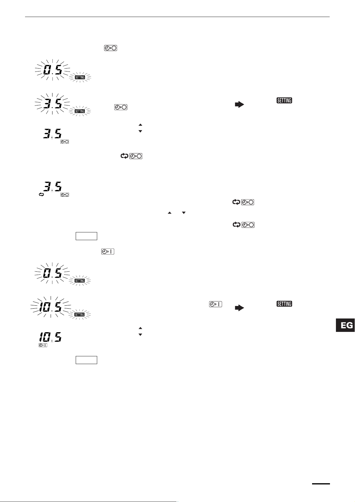
How to set the OFF timer ( )
Example: Stopping the air conditioner after 3.5 hours of operation
Operation Indication
1. Press the
conditioner.
2. Press the
3.
• Press the button until 3.5 is displayed.
• Press the button if the set time is exceeded.
4. Press the
ON/OFF
TIMER SET
mode.
SET
How to set the OFF cycle timer ( )
Example: Always stopping the air conditioner after 3.5 hours of operation
NOTE
1. Press the
2. Press the
3. Set the time using the or button.
4. Press the
When the OFF cycle timer is set, the unit will always stop after 3.5 hours of operation.
ON/OFF
TIMER SET
SET
How to set the ON timer ( )
button once to start the air
button to select the
button to set the OFF timer.
Operation
button to start the air conditioner.
button twice to select the mode.
button to set the OFF cycle timer ( ).
The and time
indications (hour) flash.
NOTE
Canceling timer operation
Example: Starting the air conditioner 10.5 hours after the ON time setting
Operation Indication
1. Press the
conditioner.
2. Press the
mode.
3.
• Press the button until 10.5 is displayed.
• Press the button if the set time is exceeded.
4. Press the
When the ON timer is set, the unit enters the paused state.
Press the CL button to cancel operation. The time setting is canceled, and the timer indicator
no longer appears on the display.
ON/OFF
TIMER SET
SET
button to start the air
button to select
button to set the ON timer.
The and time
indications (hour) flash.
19
Page 20

 Loading...