

SANYO STK442-110 Service Manual
SPECIFICATIONS
Vcc max(1)
Vcc max(2)
deg. /W
-30 to +125
Po
(W)
THD
(%)
MIN.
TYP.
MAX.
+-38
20 to 20k
+-38
+-38
20 to 20k
70
+-38
1.0
+0 -3 dB
+-38
1.0
kohm
+-46
Rg=2.2
mVrms
+-46
+-46
www.DataSheet4U.com
www.datasheet4u.com
No.
STK442-110 2000.06.05
1. Case Outline 14Pins (See attached outline drawing)
2. Function class AB 2 channels AF power amplifier
3. Application 70W audio use
4. Maximum Ratings / Ta=25deg.
Power Supply Voltage 1
Power Supply Voltage 2
Thermal Resistance Theta j-c Per one power TR 1.9
Junction Temperature Tj max 150 deg.
Operating Substrate Temperature Tc max 125 deg.
Storage Temperature Tstg
Available Time for Load
Short-circuit *4
5. Operating Characteristics
Tc=25deg.,RL =6ohm(Non-inductive Load),Rg=600ohm,VG=30dB
Output Power *1
THD *1 THD
Frequency
Characteristics *1
Input Impedance ri
Output Noise
Voltage *3
Quiescent
Current
Output Neutral
Voltage
*Specifications and information herein are subject to change without notice.
Note *1.1ch Drive
*2.All tests are measured using a constant-voltage supply unless otherwise specified.
*3.The output noise voltage is peak value of an average-reading meter with a rms value scale(VTVM).
A regulated AC supply(50Hz) should be used to eliminate the effects of AC primary line flicker
noise.
*4.Available time for load short-circuit and output noise voltage are measured using the specified
transformer power supply.
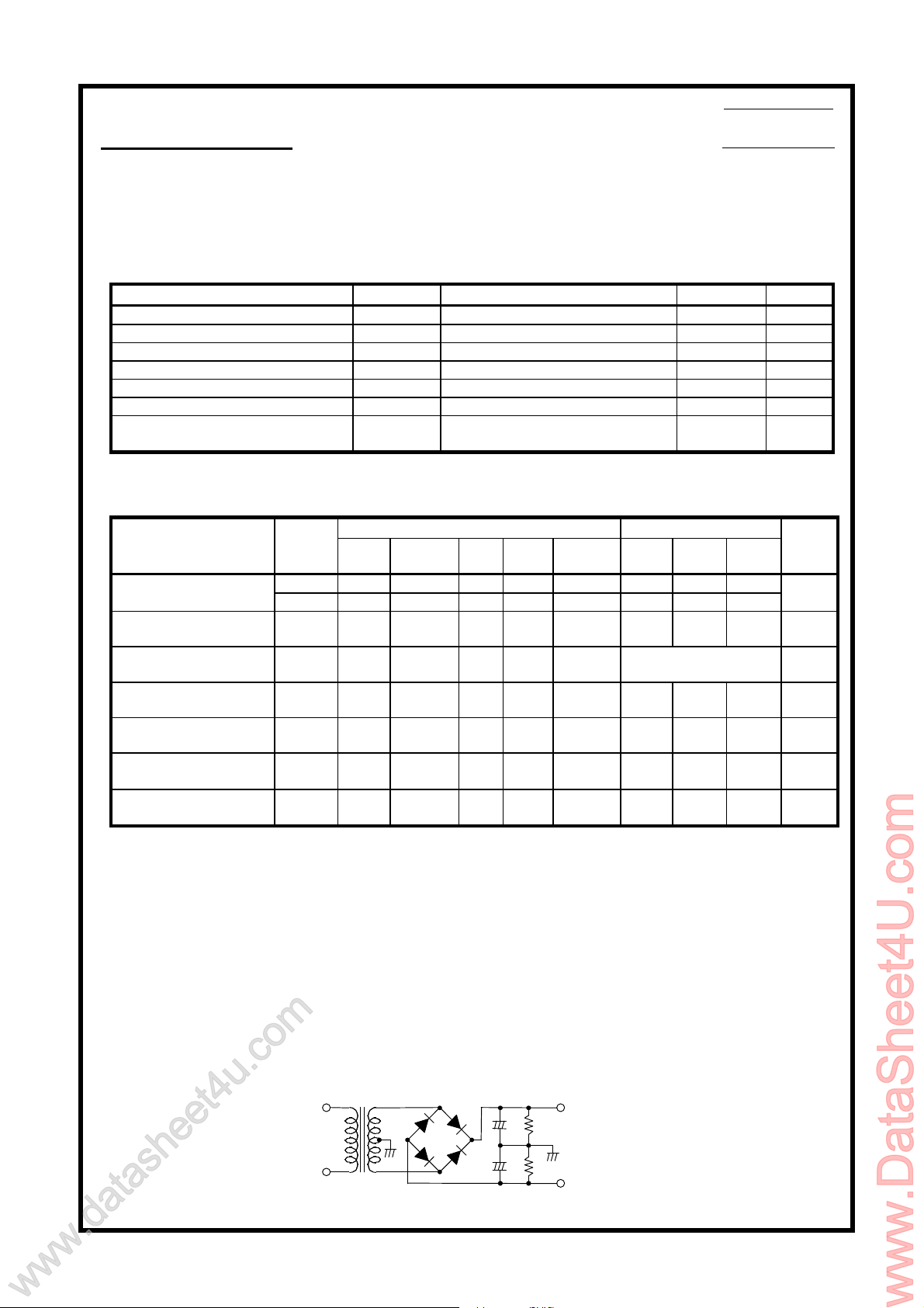
Specified Transformer Power Supply
Item Symbol Conditions Ratings Unit
No signal +-61.5 V
Signal ,R L=8ohm ,6ohm +-54 V
Vcc=+-38V,RL=6ohm,f=50Hz
PO=70W,1ch drive
Conditions *2 Ratings
f
(Hz)
0.4 70
1k 10 110
1k
10000uDBA40C
10000u
kohm
+
+
+Vcc
500ohm
500ohm
-Vcc
Item Symbol
Po1
Po2
fL ,fH
VNO
ICCO
VN
ts
V
(V)
(Equivalent to MG-250)
TENTATIVE
0.3 s
0.2 %
20 to 50k Hz
55
1.0
80 mA
-70 0 +70 mV
deg.
Unit
W
Sanyo Electric Co.,Ltd. Module Systems Division NO.1

TR3
TR4
TR5
TR6
TR7
TR9
TR13
TR14
TR15
TR16
TR17
TR18
TR19
D1
R2R4R5
R6
R7
R12
R14
R15
R16
R17
C1
SUB
TR8
731
2
6
4
5
8
12
11109
R3
R13
TR1
TR2D2D3
TR12
TR11
TR10
TR20
13
14
C4R8C5
R18
C7C8C10
C11
100uF
/100v
100uF
/100v
100ohm/1W
100uF
100uF
1.8kohm
1.8kohm
56kohm
3pF
56kohm
3pF
100uF
20kohm
100uF
3uH
3uH
4.7ohm
4.7ohm/1W
4.7ohm
4.7ohm/1W
0.1uF
220pF
56kohm
56kohm
470pF
470pF
2.2uF
/50v
2.2uF
/50v
1kohm
1kohm
220pF
(*1)
0.1uF
100ohm/1W
+Vcc
Ch1
Ch1
Ch2
Ch2
Ch2
Ch2
Ch1
Ch1
-Vcc
SUB
-PRE
+PRE
BIAS
(*1)
(*1)
(*1)
Equivalent Block Diagram
Test Circuit
+Vcc
GND
/100v
1 2
+RE
-RE
-RE
+RE
NF
NF
IN
IN
3 4 5 6 7 8 9 10 11 12 13 14
/10v
/10v
Ch2 IN
GND
Ch1 IN
Ch2 OUT
GND
-Vcc
/100v
Ch1 OUT
SUB.GND
(*1)Metal Plate Cement Resistor 0.22ohm+-10%(5W)
No.2
 Loading...