

SANYO STK4036II Datasheet

± 52 V
Ordering number: EN 1707B
θ
°
° C
° C
−
° C
s
± 35 V
8
Thick Film Hybrid IC
STK4036 II
AF Power Amplifier (Split Power Supply)
(50W min, THD = 0.4%)
Features
• Compact package for thin-type audio sets
• Member of pin-compatible series with outputs of 20 to
200W
• Easy heatsink design to disperse heat generated in thintype stereo sets
• Constant-current circuit to reduce supply switch-on and
switch-off shock noise
• External supply switch-on and switch-off shock noise
muting, load short-circuit protection, thermal shutdown
and other circuits can be tailor-designed.
Specifications
Maximum Ratings
at Ta = 25 ° C
Package Dimensions
unit: mm
4033
[STK4036 II ]
Parameter Symbol Conditions Ratings Unit
Maximum supply voltage V
Thermal resistance
Junction temperature Tj 150
Operating substrate temperature Tc 125
Storage temperature Tstg
Available time for load short-circuit
1
Recommended Operating Conditions
Parameter Symbol Conditions Ratings Unit
Recommended supply voltage V
Load resistance R
max
CC
j-c 1.8
30 to +125
V
= ± 35V, R
t
s
CC
f = 50Hz, P
= 8 Ω ,
L
= 50W
O
at Ta = 25 ° C
CC
L
SANYO Electric Co., Ltd. Semiconductor Business Headquarters
TOKYO OFFICE Tokyo Bldg., 1-10, 1 Chome, Ueno, Taito-ku, TOKYO, 110 JAPAN
60697HA (ID) / 32596HA (ID) / 8298MO / 1075MY, TS No. 1707—1/3
C/W
2
Ω
mA
W
W
%
Hz
k Ω
−
STK4036 II
Operating Characteristics
at Ta = 25 ° C, V
= ± 35V, R
CC
= 8 Ω (noninductive load), Rg = 600 Ω , VG = 40dB
L
Parameter Symbol Conditions min typ max Unit
Quiescent current I
P
CCO
(1)
O
Output power
P
(2)
O
Total harmonic distortion THD P
Frequency response f
Input impedance r
Output noise voltage
2
Neutral voltage V
, f
L
H
i
V
NO
N
V
= ± 42V 10 20 50
CC
THD = 0.4%, f = 20Hz to
20kHz
V
= ± 31V, THD = 1.0%,
CC
R
= 4 Ω , f = 1kHz
L
= 1.0W, f = 1kHz – – 0.3
O
P
O
P
O
V
CC
V
CC
+0
= 1.0W, – 20 to 50k –
dB
−
3
= 1.0W, f = 1kHz – 55 –
= ± 42V, Rg = 10k Ω
= ± 42V
50 – –
55 – –
– – 1.2
70 0 +70
mVrms
mV
Notes.
All tests are measured using a constant-voltage supply unless otherwise specified.
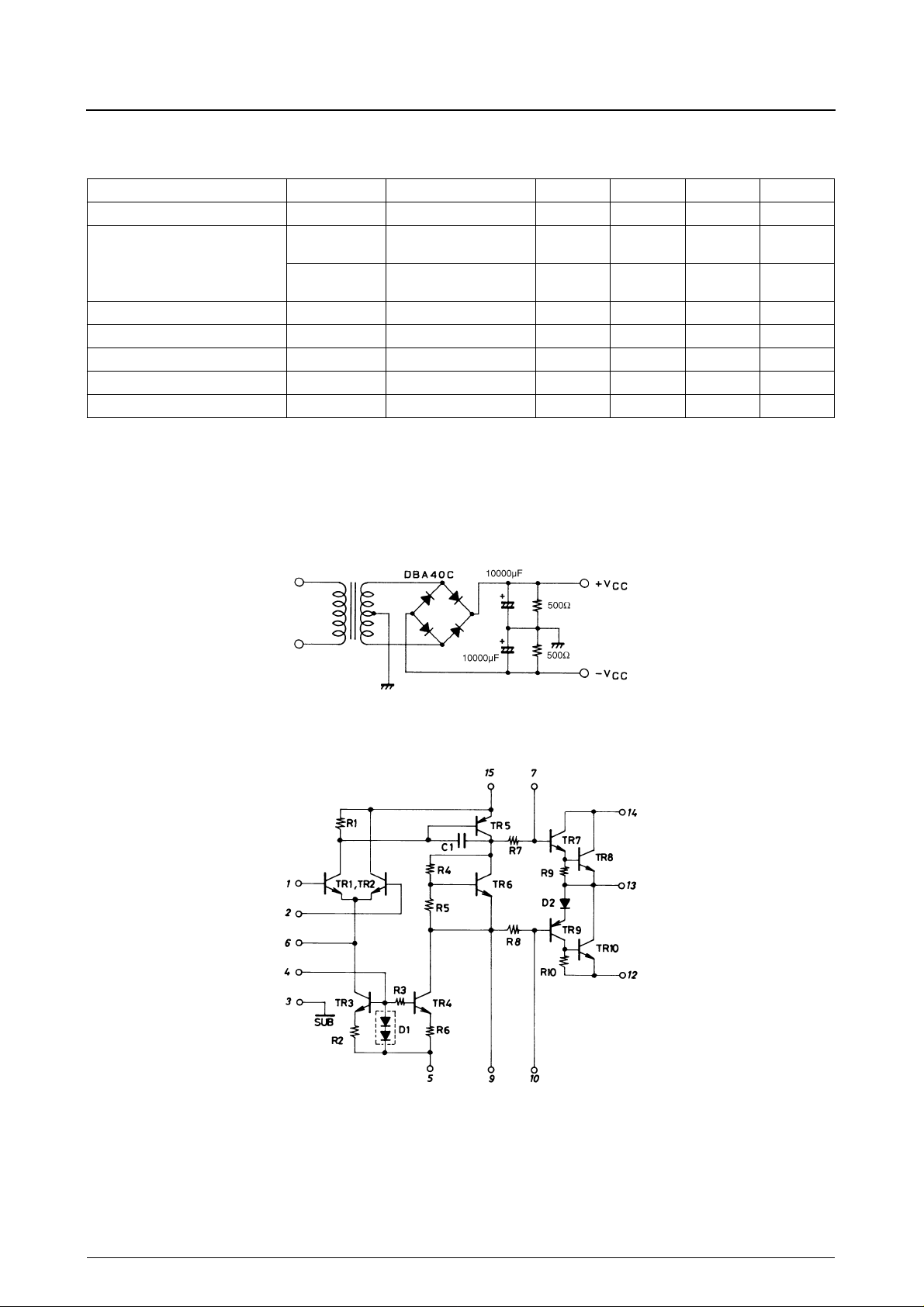
1. Output noise voltage is measured using the transformer supply specified below.
2. The output noise voltage is the peak value of an average-reading meter with an rms value scale. The noise voltage waveform does not
inlcude any pulse noise.
Specified Transformer Supply (MG-200 or Equivalent)
Equivalent Circuit
No. 1707—2/3
 Loading...