

Sanyo SAP- FR99EH, SAP- FTR129EH Technical Data & Service Manual
TECHNICAL DATA
& SERVICE MANUAL
INDOOR UNIT:
SAP- FR99EH
SAP- FTR129EH
SPLIT SYSTEM AIR CONDITIONER
SAP- FR99EH
Floor Mounted
SAP- FTR129EH
Ceiling Mounted
SM940013
Model No. Product Code No.
SAP- FR99EH 1 85208179
0.8180.279.0 07/2002
SAP- FTR129EH 1 85208181
IMPORTANT!
Please read before installation
This air conditioning system meets strict safety and operating
standards.
For the installer or service person, it is important to install or
service the system so that it operates safely and efficiently.
For safe installation and trouble-free operation, you must:
• Carefully read this instruction booklet before beginning.
• Follow each installation or repair step exactly as shown.
• Observe all local, state and national electrical codes.
• Pay close attention to all warning and caution notices given in
this manual.
•The unit must be supplied with a dedicated electrical line.
This symbol refers to a hazard or unsafe practice which can result
in severe personal injury or death.
This symbol refers to a hazard or unsafe practice which can result
in personal injury or product or property damage.
If necessary, get help
These instructions are all you need for most installation sites and
maintenance conditions.
If you require help for a special problem, contact our sale/service
outlet or your certified dealer for additional instructions.
In case of improper installation
The manufacturer shall in no way be responsible for improper
installation or maintenance service, including failure to follow the
instructions in this document.
SPECIAL PRECAUTIONS
• During installation, connect before the refrigerant system and
then the wiring one; proceed in the reverse orden when removing
the units.
When wiring
ELECTRICAL SHOCK CAN CAUSE SEVERE
PERSONAL INJURY OR DEATH. ONLY A QUALIFIED,
EXPERIENCED ELECTRICIANS SHOULD ATTEMPT
TO WIRE THIS SYSTEM.
• Do not supply power to the unit until all wiring and tubing are
completed or reconnected and checked, to ensure the grounding.
• Highly dangerous electrical voltages are used in this system.
Carefully refer to the wiring diagram and these instructions when
wiring.
Improper connections and inadequate grounding can cause
accidental injury and death.
• Ground the unit following local electrical codes.
• The Yellow/Green wire cannot be used for any connection
different from the ground connection.
• Connect all wiring tightly. Loose wiring may cause overheating
at connection points and a possible fire hazard.
• Do not allow wiring to touch the refrigerant tubing, compressor,
or any moving parts of the fan.
• Do not use multi-core cable when wiring the power supply and
control lines. Use separate cables for each type of line.
When transporting
Be careful when picking up and moving the indoor and outdoor
units. Get a partner to help, and bend your knees when lifting to
reduce strain on your back. Sharp edges or thin aluminium fins on
the air conditioner can cut your fingers.
When installing...
... In a ceiling or wall
Make sure the ceiling/wall is strong enough to hold the unit-weight.
It may be necessary to build a strong wooden or metal frame to
provide added support.
... In a room
Properly insulate any tubing run inside a room to prevent
"sweating", which can cause dripping and water damage to walls
and floors.
... In moist or uneven locations
Use a raised concrete base to provide a solid level foundation for
the outdoor unit.
This prevents damage and abnormal vibrations.
... In area with strong winds
Securely anchor the outdoor unit down with bolts and a metal
frame. Provide a suitable air baffle.
... In a snowy area (for heat pump-type systems)
Install the outdoor unit on a raised platform that is higher than
drifting snow. Provide snow vents.
When connecting refrigerant tubing
• Keep all tubing runs as short as possible.
• Use the flare method for connecting tubing.
• Apply refrigerant lubricant to the matching surfaces of the flare
and union tubes before connecting them; screw by hand and
then tighten the nut with a torque wrench for a leak-free
connection.
• Check carefully for leaks before starting the test run.
NOTE:
Depending on the system type, liquid and gas lines may be either
narrow or wide. Therefore, to avoid confusion, the refrigerant
tubing for your particular model is specified as narrow tube for
liquid, wide tube for gas.
When servicing
• Turn the power OFF at the main power board before opening
the unit to check or repair electrical parts and wiring.
• Keep your fingers and clothing away from any moving parts.
• Clean up the site after the work, remembering to check that no
metal scraps or bits of wiring have been left inside the unit being
serviced.
• Ventilate the room during the installation or testng the refrigeration
system; make sure that, after the installation, no gas leaks are
present, because this could produce toxic gas and dangerous
if in contact with flames or heat-sources.
WARNING
CAUTION
WARNING
2
Page
1. SPECIFICATIONS
4
1-1 Unit specifications 4
1-2 Major Component specifications 6
1-3 Other Component specifications 8
2. DIMENSIONAL DATA
9
3. PERFORMANCE DATA
11
3-1 Air Throw Distance Chart 11
4. ELECTRICAL DATA
13
4-1 Electric Wiring Diagrams 13
5. FUNCTION
14
5-1 Room Temperature Control 14
5-2 Dry Operation (Dehumidification) 16
5-3 Automatic Switching between Cooling and Heating 16
5-4 Freeze Prevention (Cooling and Dry) 17
5-5 Compressor Overcurrent Protection (Cooling, Dry and Heating) 17
5-6 Overload Prevention (Heating) 18
5-7 Cold Draft Prevention (Heating) 19
5-8 Defrosting Operation (Heating) 20
6. TROUBLESHOOTING
22
6-1 Check before and after troubleshooting 22
6-2 Air conditioner does not operate 23
6-3 Some part of air conditioner does not operate 27
6-4 Air conditioner operates, but abnormalities are observed 29
6-5 If a sensor is defective 31
7. CHECKING ELECTRICAL COMPONENTS
32
7-1 Measurement of Insulation Resistance 32
7-2 Checkin
g
Continuity of Fuse on PCB Ass'
y
33
7-3 Checking Motor Capacitor 33
8. MAINTENANCE
34
8-1 Changing Address of Remote Control Unit in Indoor Unit 34
Table of Contents
3
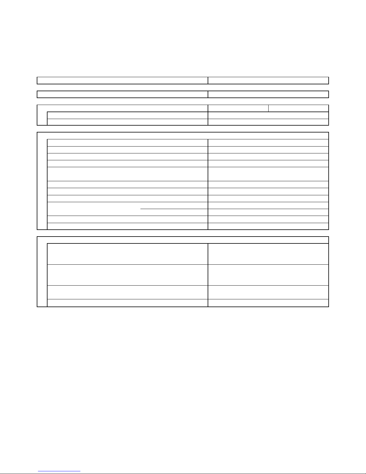
1. SPECIFICATIONS
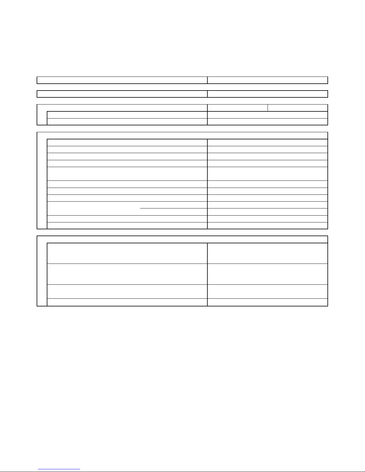
1-1 Unit Specifications
SAP- FR99EH
Power source
V
oltage ratin
g
Performance
Capacity
A
ir circulation
High
m³/h
Features
Controls/Temperature controls
Control unit
Timer
Fan speed
Airflow direction Horizontal
Vertical
Air Filter
Operation Sound High dB(A)
Refrigerant tubing connections
Refrigerant Narrow tube mm(in.)
tube diameter Wide tube mm(in.)
Refrigerant
Refrigerant tube kit / Air clean filter
Dimensions & Wei
g
ht
Unit dimensions Height mm
Width mm
Depth mm
Package dimensions Height mm
Width mm
Depth mm
Weight Net kg
Shipping kg
Shipping volume
m
3
DATA SUBJECT TO CHANGE WITHOUT NOTICE
ON/OFF 24 hours & Daily program, 1-hour OFF
3 and Auto /1(Hi)
Manual
Manual
Washable, Anti-Mold
51
Flare type
6,35 (1/4)
9,52 (3/8)
R22 or R407C
Optional / Optional
700
560
200
770
620
265
18
20
0,13
220 - 240 V ~ 50 H
z
230 V
Cooling Heating
Wireless remote control unit
See catalogue with the requested matching
Microprocessor/ I.C. thermostat
400
4
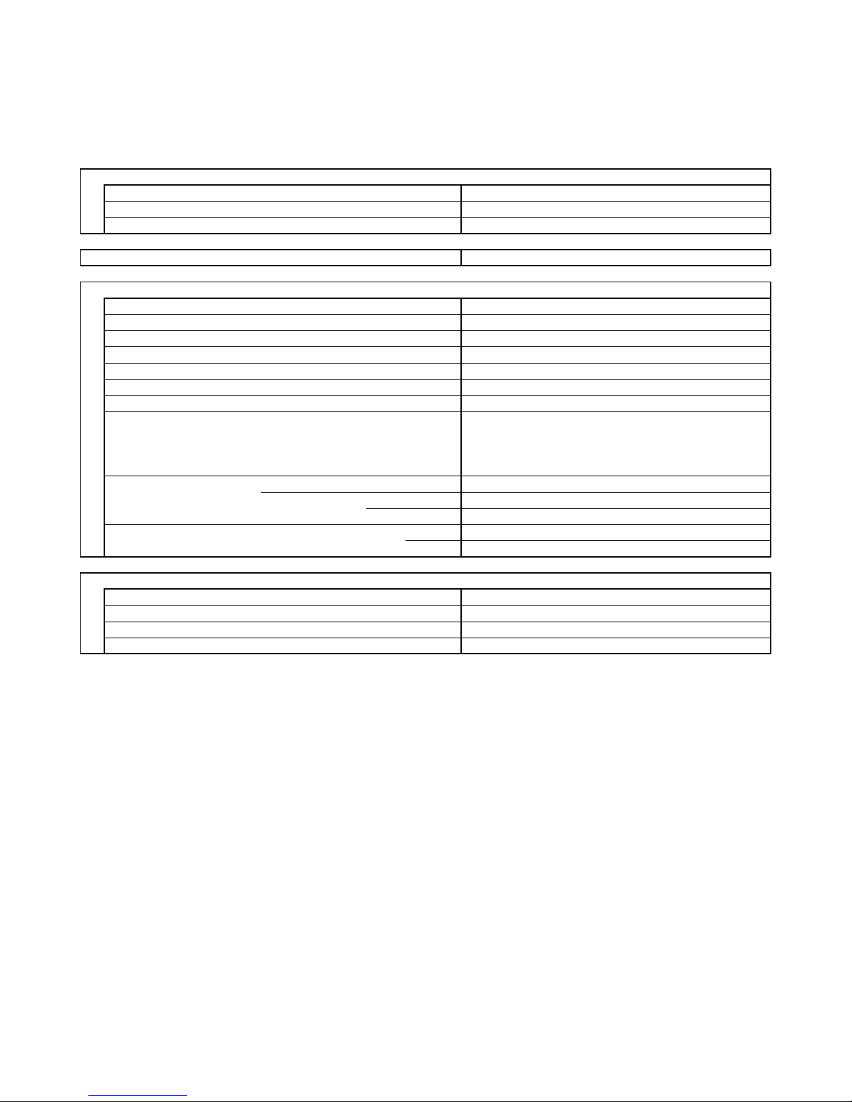
SAP- FTR129EH
Power source
V
oltage ratin
g
Performance
Capacity
Air circulation
High
m³/h
Features
Controls/Temperature controls
Control unit
Timer
Fan speed
Airflow direction Horizontal
Vertical
Air Filter
Operation Sound High dB(A)
Refrigerant tubing connections
Refrigerant Narrow tube mm(in.)
tube diameter Wide tube mm(in.)
Refrigerant
Refrigerant tube kit / Air clean filter
Dimensions & Wei
g
ht
Unit dimensions Height mm
Width mm
Depth mm
Package dimensions Height mm
Width mm
Depth mm
Weight Net kg
Shipping kg
Shipping volume
m
3
DATA SUBJECT TO CHANGE WITHOUT NOTICE
0,21
995
280
23,5
31,5
680
900
190
770
A
uto
Washable, Anti-Mold
55
Flare type
Wireless remote control unit
ON/OFF 24 hours & Daily program, 1-hour OFF
3 and Auto /1(Hi)
Manual
See catalogue with the requested matching
Microprocessor/ I.C. thermostat
700
220 - 240 V ~ 50 H
z
230 V
Cooling Heating
6,35 (1/4)
12,7 (1/2)
R22 or R407C
Optional / Optional
5
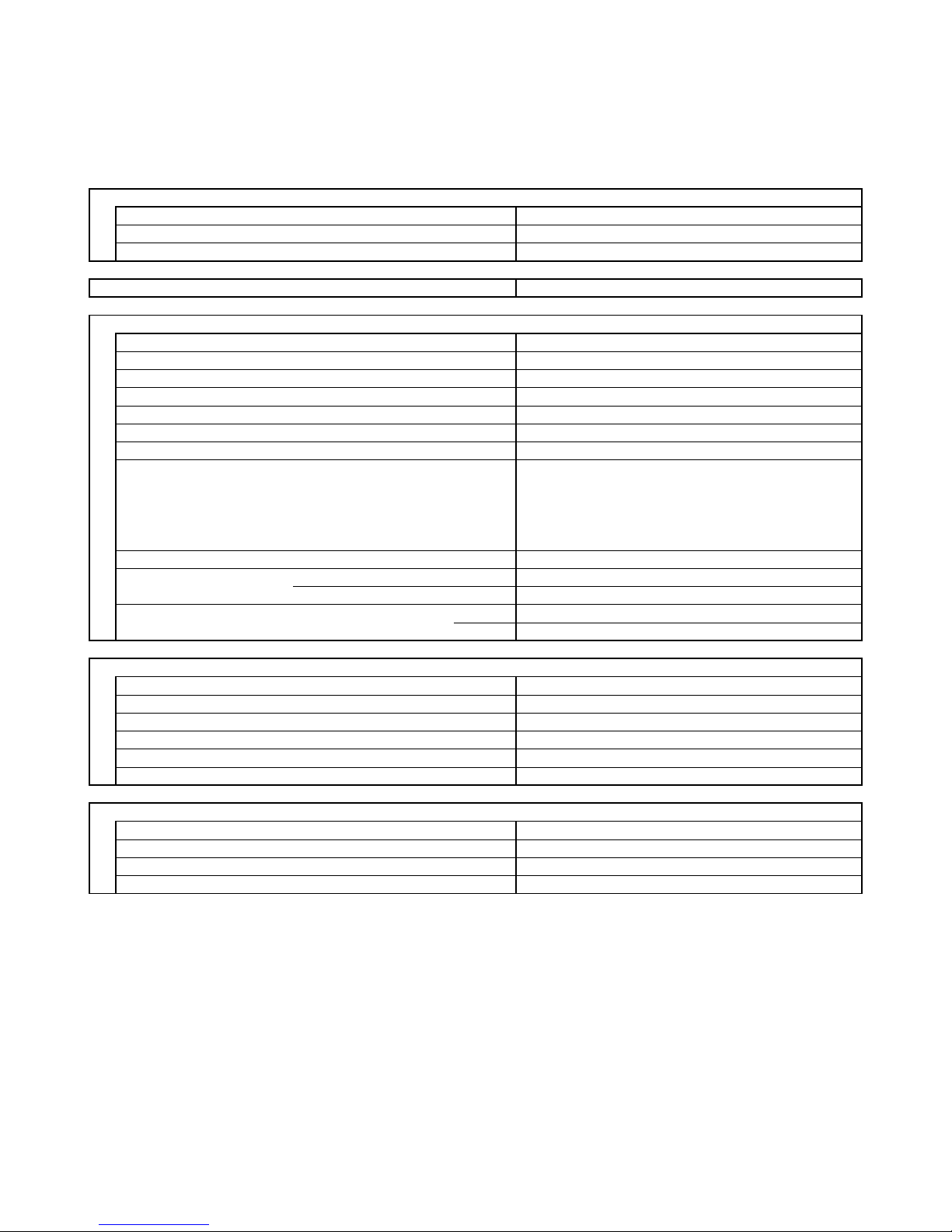
1-2 Major Component Specifications
SAP- FR99EH
Controller PCB
Part No.
Controls
Control circuit fuse
Remote Control Unit
Fan & Fan Motor
Type
Q'ty ……. Dia. and lenght mm
Fan motor model…Q'ty
No. of poles…rpm (230 V, High)
Nominal output W
Running Amps A
Power input W
Coil resistance (Ambient temp. 25 °C )
Ω
Safety devices Type
Operating temp. Open °C
Close
Run capacitor µF
VAC
Heat Exch. Coil
Coil
Rows
Fin pitch mm
Face area m²
DATA SUBJECT TO CHANGE WITHOUT NOTICE
1,4
450
WHT-VLT: 92÷105
VLT-YEL: 62÷71
GRY-BRN: 78÷90
1
Thermal protection
150 ± 10
A
utomatic
0,185
XR99EH-(SA)
RCS-6HPS4E-G
Cross - flow
K35406-M01892…1
4…1196
A
luminium plate fin / Copper tube
1
27
GRY-WHT: 545÷630
Microprocessor
250 V - 3,15
A
1…. Ø 100 / L 410
0,12
26
6
SAP- FTR129EH
Controller PCB
Part No.
Controls
Control circuit fuse
Remote Control Unit
Fan & Fan Motor
Type
Q'ty ……. Dia. and lenght mm
Fan motor model…Q'ty
No. of poles…rpm (230 V, High)
Nominal output W
Running Amps A
Power input W
Coil resistance (Ambient temp. 25 °C )
Ω
Safety devices Type
Operating temp. Open °C
Close
Run capacitor µF
VAC
Flap Motor
Type
Model
Rating
No. of poles…rpm
Nominal output W
Coil resistance (Ambient temp. 25 °C )
κ
Ω
Heat Exch. Coil
Coil
Rows
Fin pitch mm
Face area
DATA SUBJECT TO CHANGE WITHOUT NOTICE
0,29
65
XR129EH-(SA)
Microprocessor
250 V - 3,15
A
RCS-6HPS4E-G
Cross - flow
2…. Ø 130 / L 180
K48407-M01596…1
4…1160
21
GRY-WHT: 298÷343
ORG-YEL: 211÷243
Thermal protection
145 ± 5
WHT-PNK: 421÷485
WHT-VLT: 93,5÷108
VLT-ORG: 93,5÷108
A
utomatic
1.5
440
Synchro moto
r
M2LJ24ZE31
2,5÷3
16,45±15%
A
C 208/230 V ; 50-60 H
z
8…2,5÷3
A
luminium plate fin / Copper tube
2
1,8
0,192
7
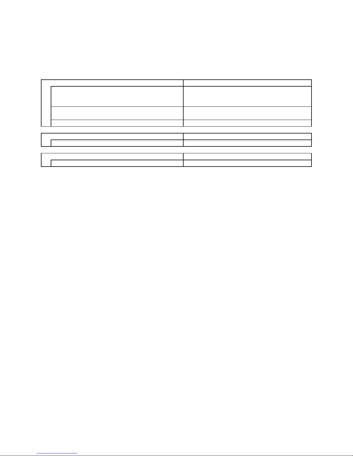
1-3 Other Component Specifications
SAP- FR99EH
SAP- FTR129EH
Trasformer (TR
)
Rating Primary
Secondary
Capacity
Coil resistance
Ω
(
at 21°C
)
Thermal cut-off temp.
Thermistor
(
Coil sensor TH1
)
Resistance
κ
Ω
Thermistor
(
Room sensor TH2
)
Resistance
κ
Ω
KTEC-35-S6
25 °C: 5,0 ± 4%
PCB-41E-S14
Primary (WHT-WHT): 205 ± 10%
Secondary (BRN-BRN): 2 ± 10%
150°C
0 °C: 15,0 ± 5%
A
TR-J105
A
C 230 V ; 50-60 H
z
19 V ; 0.526
A
10 V
A
8
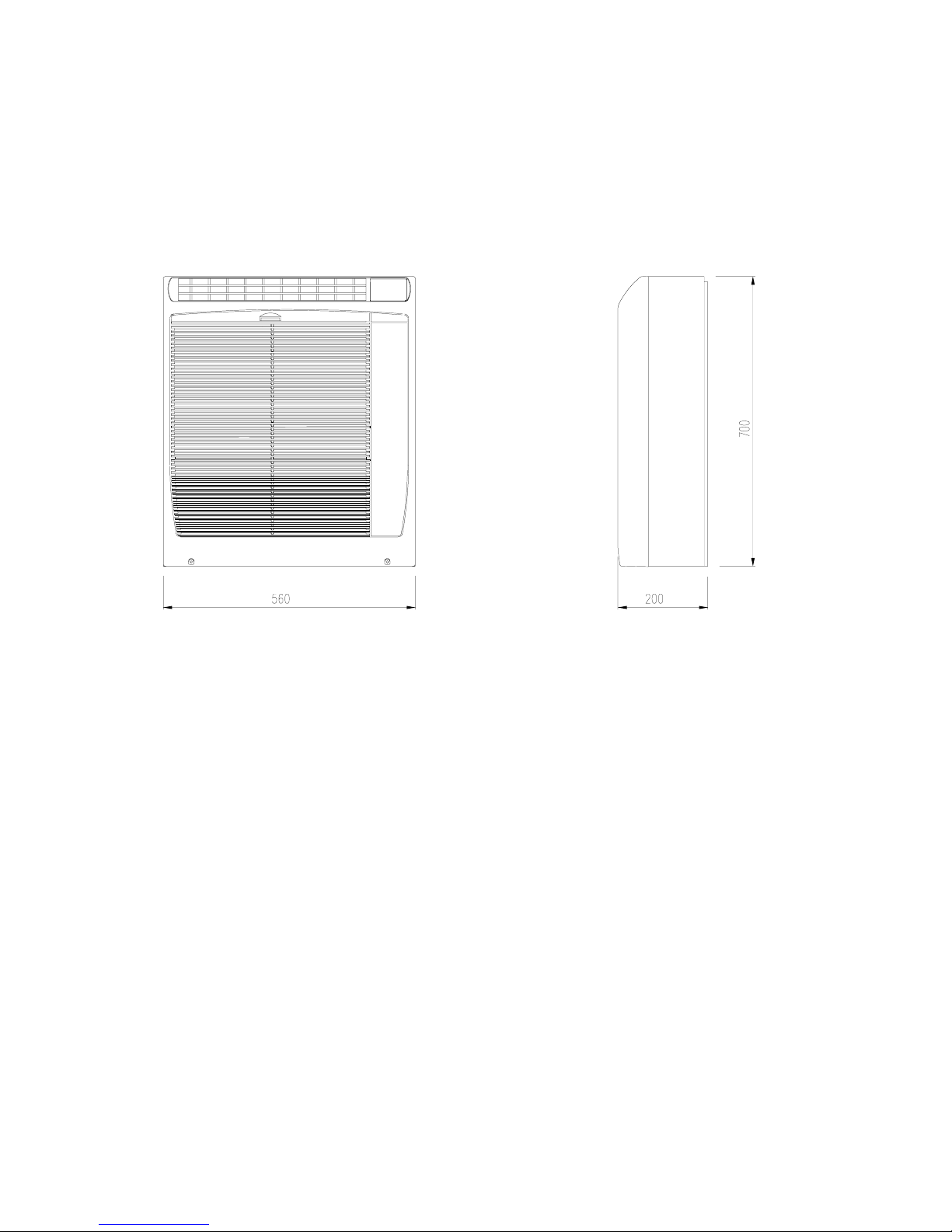
2. DIMENSIONAL DATA
SAP- FR99EH
Unit: mm
9
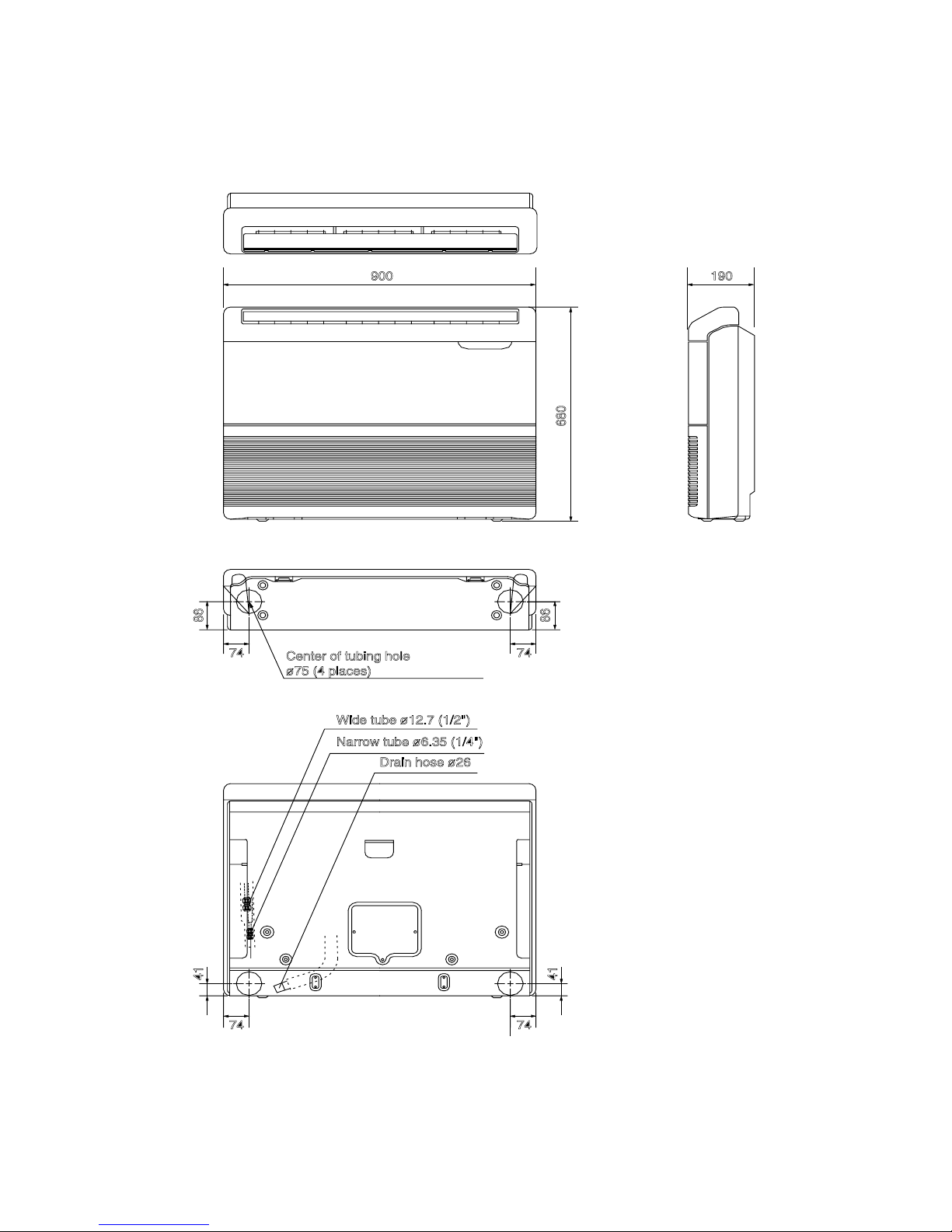
SAP- FTR129EH
Unit: mm
Unit: mm
10
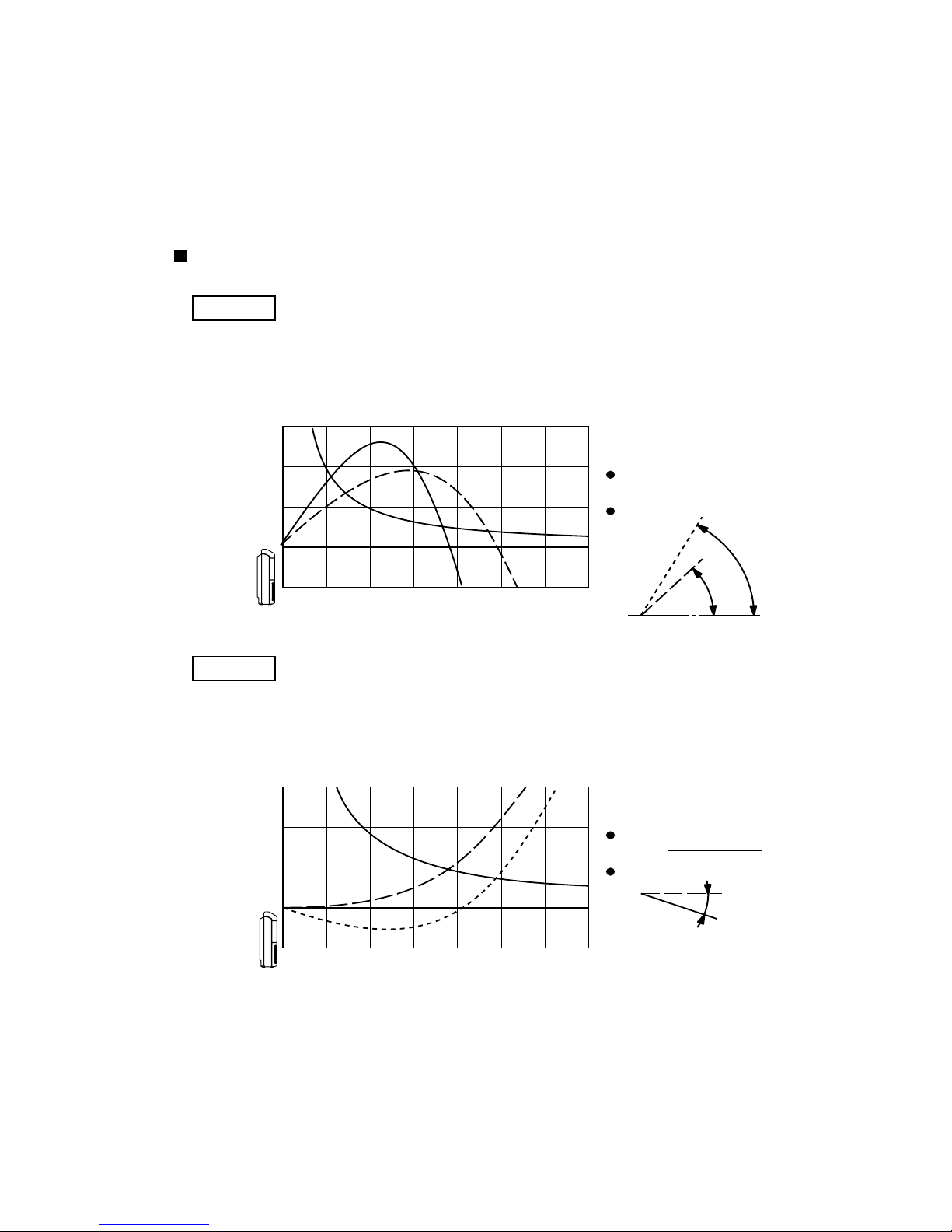
3. PERFORMANCE DATA
3-1 Air Throw Distance Chart
SAP- FTR129EH
Room air temp. : 27°C
Fan speed : High
Axis air velocity
Flap angle
60°
45°
Floor mounted
Cooling
01234567
3
2
1
0
Horizontal distance (m)
Axis air velocity (m/s)
Vertical distance (m)
01234567
3
2
1
0
Horizontal distance (m)
Axis air velocity (m/s)
Vertical distance (m)
Room air temp. : 20°C
Fan speed : High
Axis air velocity
Flap angle
Heating
0°
–20°
11
 Loading...