

Page 1
INSTRUCTION MANUAL
FIRST MADE FOR SAP-KC9,12,18,25,30AP
MATERIAL OR MODEL *PAPER-JO
DIMENSION OR MAKER WOODFREE 80gm
COLOR BLACK Print
EZIS4AETON
APPROVALS
N.Yamazaki
2010/Feb/1
CHECK
Tai C.S
2010/Feb/1
DESIGN
Tai C S
2010/Feb/1
DRAWN
REMARKS:
SAMS ONLY
1
ON.RSNOISIVERETADSLAVORPPA
PART CODE
85S-6-4181-007-00-0
PART NAME
EXPLANATORY BOOKLET
Page 2
INSTRUCTION MANUAL
Split System Air Conditioner
INDOOOR UNIT OUTDOOR UNIT
COOL / DRY MODEL
SAP-K9AP
SAP-C9AP
SAP-K12AP SAP-C12AP
SAP-K18AP SAP-C18AP
SAP-K25AP SAP-C25AP
SAP-K30AP SAP-C30AP
HA1-PHA21K-PAS
Save These Instructions!
Pub. OI-85S64181007000 © SANYO 2010
SANYO Electric Co., Ltd.
Page 3
Instruction Manual
Features
Features
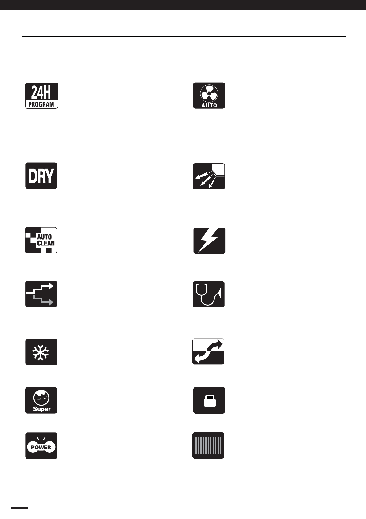
This air conditioner is equipped with cooling and drying functions. Details on these functions are
provided below; refer to these descriptions when using the air conditioner.
24-hour Clock with ON/OFF
Program Timer
The remote control unit allows you
to set a wide variety of timer-based
operations including automatic
ON/OFF with timer setting, sametime ON/OFF every day, ON timer,
OFF timer and Combination timer.
Mild Dry
By coupling the compressor and
fan operation, intermittent drying
can be precisely controlled
according to room temperature so
that air is efficiently dehumidified.
Auto Clean
Fan operates when the unit is
stopped to prevent the generation
of mould and odors within the
indoor unit.
Automatic Fan Operation
Convenient microprocessor control
automatically adjusts fan speed to
High, Medium or Low, according to
room temperature to maintain a
comfortable airflow throughout the
room.
Air Sweep Control
The air sweep function moves the
flap up and down in the air outlet,
directing air in a sweeping motion
around the room and providing
comfort to every corner.
Automatic Restart Function for
Power Failure
Even when power failure occurs.
Preset programmed operation is
Reactivated once power resumes.
Humanized Sleep Function
Temperature gently rises or falls
automatically to maintain
comfortable room temperature and
saves energy.
Rapid Cooling
The high-efficient system makes
Cooling fast but still remains high
EER/COP.
Super Quiet
Specially-designed air vent
efficiently reduce noise.
Turbo
Cools the room intensely.
Self Diagnosis
Error code is displayed for fast and
easy maintenance, should a
problem occurs.
Low Voltage Startup (Min.198V)
The unit starts safely even when
the voltage is below the rated
voltage.
Child Lock
Remote controller keys are
lockable to prevent misoperation.
Blue Fin
Anti-corrosion blue fin is more
effective than a common coil.
1
Page 4
Instruction Manual
Contents
Instruction Manual
Page
Features
...............................................
................................. 1
Operation and Maintenance
1. Notices for operation .............................................................
2. Notices for user .................................................................
3. Names and functions of each part .....................................
4. Operation of wireless remote control unit ..........................
5. Clean and care .................................................................
6. Troubleshooting ................................................................
Installation Service
7. Notices for installation ...........................................................
8. Installation dimension diagram . ........................................
9. Install indoor unit ..............................................................
10. Install outdoor unit ............................................................
11. Pump down .......................................................................
12. Check after installation and Test operation ......................
13. Self diagnosis function .....................................................
3
5
6
7
15
17
19
21
22
26
32
33
34
Product Information
If you have problems or questions concerning your Air Conditioner,
you will need the following information. Model and serial numbers
are on the nameplate on the bottom of the cabinet.
Model No. _______________Serial No. _____________________
Date of purchase _______________________________________
Dealer’s addres _______________________________________
Phone number_________________
Thank you for choosing SANYO air conditioner, please read
this instruction manual carefully before operating the unit
and keep it carefully for consultation.
Alert Symbols
The following symbols used in this manual, alert you to
potentially dangerous conditions to users, service personnel
or the appliance:
This symbol stands for the items should be forbidden.
This symbol stands for the items should be followed.
2
Page 5
Operation and Maintenance
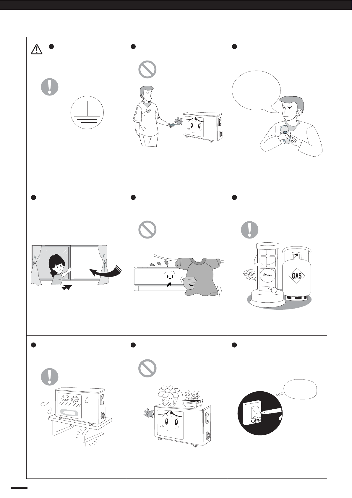
1. NOTICES FOR OPERATION
Each unit must be
properly grounded with a
ground (or earth) wire or
through the supply wiring.
If not, please ask the qualified
personnel to install.
Furthermore, do not connect
each wire to the gas pipe,water
pipe, drainage pipe or any other
improper places.
Don't leave windows and doors
open for a long time while operating
the air conditioner.
Don't attempt to repair the air
conditioner by yourself.
The wrong repair will lead to an
electric shock or fire, so you
should contact the SANYO
service center for repair.
Don't block the air intake or outlet
vents of both the outdoor and indoor
units.
Select the most appropriate
temperature.
Keep room
cooler than
outside about
o
5 C.
It can help to preclude the
electricity wasted.
Never use or store gasoline or
other flammable vapor or liquid
near the air conditioner.
It can decrease the air
conditioning capacity.
Please make sure whether
the installed stand is firm
enough or not.
If it is damaged, it may lead to
the fall of the unit and cause the
injury.
It can decrease the air conditioning
capacity or cause a malfunction.
Do not step on the top of the
outdoor unit or place things on it.
As falling off the outdoor unit can
be dangerous.
It is very dangerous and it may
cause a fire or explosion.
If abnormal phenomenon (like
burning odor, etc) occur, turn off
power supply and contact
SANYO service center.
Cut Off
Power
If abnormal phenomenon
Icontinues, the unit may be
damaged and cause electric
shock or fire.
3
Page 6
Operation and Maintenance
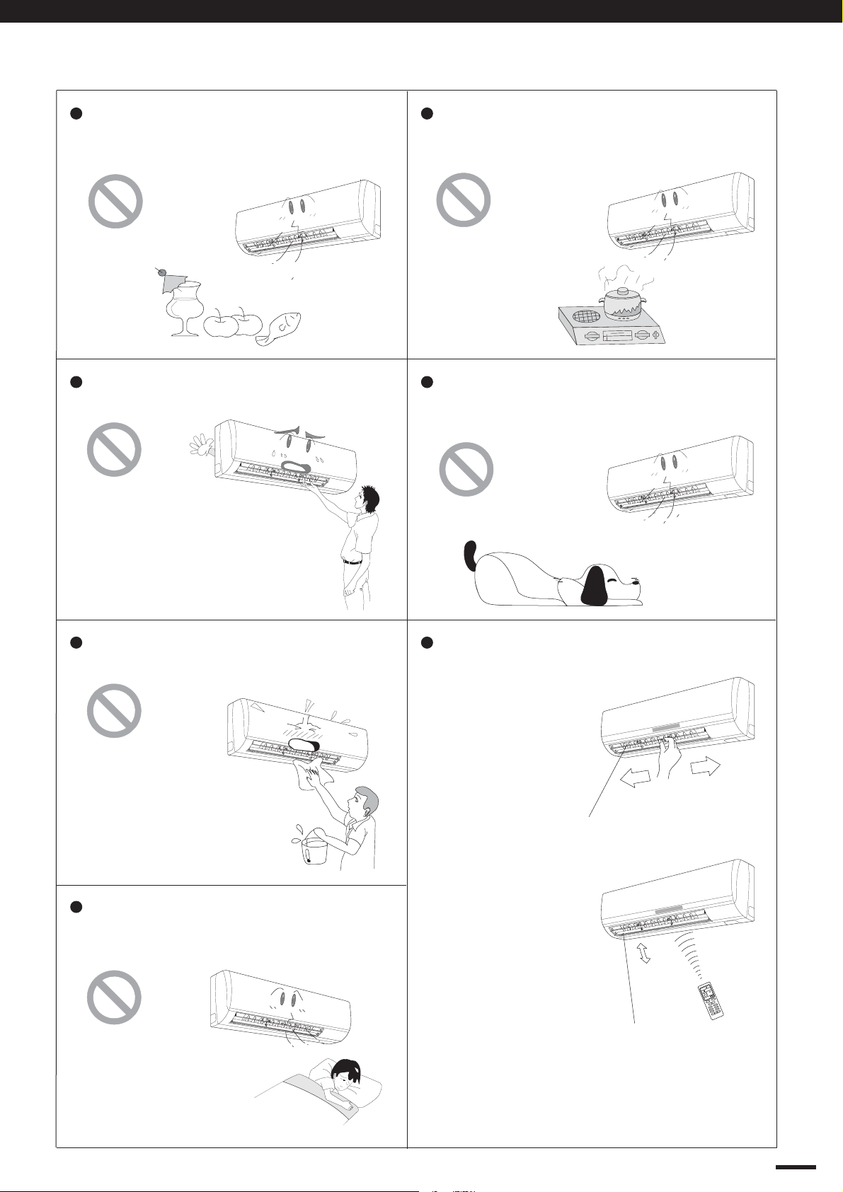
1. NOTICES FOR OPERATION
Do not use the air conditioner for other
purposes,such as drying clothes,
preserving foods, etc.
Do not insert your hands or stick into
the air intake or outlet vents.
Do not place a space heater near the air
conditioner. CO toxicosis may occur as
a result of imcomplete burning.
Do not blow the wind to animals and
plants directly. It can cause a bad
influence to them.
Splashing water on the air conditioner
can cause electric shock or malfunction.
Do not apply the cold wind to the body
for a long time. It can cause the health
problems.
Adjusting the airflow direction correctly.
a) Horizontal:
The horizontal
airflow can be
adjusted by
moving the
louver with
your hand
to the left
or right.
Louver of left /
right direction.
b) Vertical:
The vetical air
flow can be
adjusted by
moving the flap
OPER
FAN
with the remote
control unit.
Use the SWING
button to set
Flap of upward /
downward position.
C
SWING
AM
ON
E
D
O
M
F
F
O
/
N
+
O
P
M
E
T
P
M
E
T
G
N
I
W
S
K
N
C
A
O
L
F
C
F
P
F
E
E
O
-
L
T
S
+
N
O
E
-
M
I
T
T
L
E
C
N
A
C
E
M
I
T
either the auto
sweep or set to the
recommended position.
4
Page 7
2. NOTICES FOR USER
Operation and Maintenance
2.1 Working Principle &
Special Functions
for Cooling
2.2 Working Temperature Range
Temperature Indoor air temperature Outdoor air temperature
Max.
COOLING
Min.
Principle:
Air conditioner absorbs heat in the room and transmit to
outdoor and discharged, so that indoor ambient
temperature decreased. It's cooling capacity will decrease
by the increase of outdoor ambient temperature.
Anti-freezing Function:
If the units is running in COOL mode and in low
temperature, there will be frost formed on the heat
exchanger, when indoor heat exchanger temperature
decreased below 0 C, the indoor unit micro-computer will
stop compressor running and protect the unit.
32 °C DB / 23 °C WB
21 °C DB / 15 °C WB
o
52 °C DB / ---
21 °C DB / ---
The operating temperature range (outdoor temperature) for cooling unit is 21 °C ~ 52 °C.
2.3 The Conditions of Unit Can't Operate Normally.
In the following temp. range, the protection device may act, this may cause unit stop running.
Outdoor temperature
above
“COOL” running
“DRY” running
Under the relative humidity is above 80% ( doors and windows are opened) when cooling or
dehumidifying for a long time, there may have dew drip off near the air vent.
52°C 32°C
52°C
Outdoor temperature
below
21°C
18°C 32°C
Indoor temperature
above
5
Page 8
S/n
)
cable
)
e c
l
)
)
er
)
)
dica
Cool
Dry
Fa
Ru
S
)
Wall Pipe
d T
)
e
)
e
Operation and Maintenance
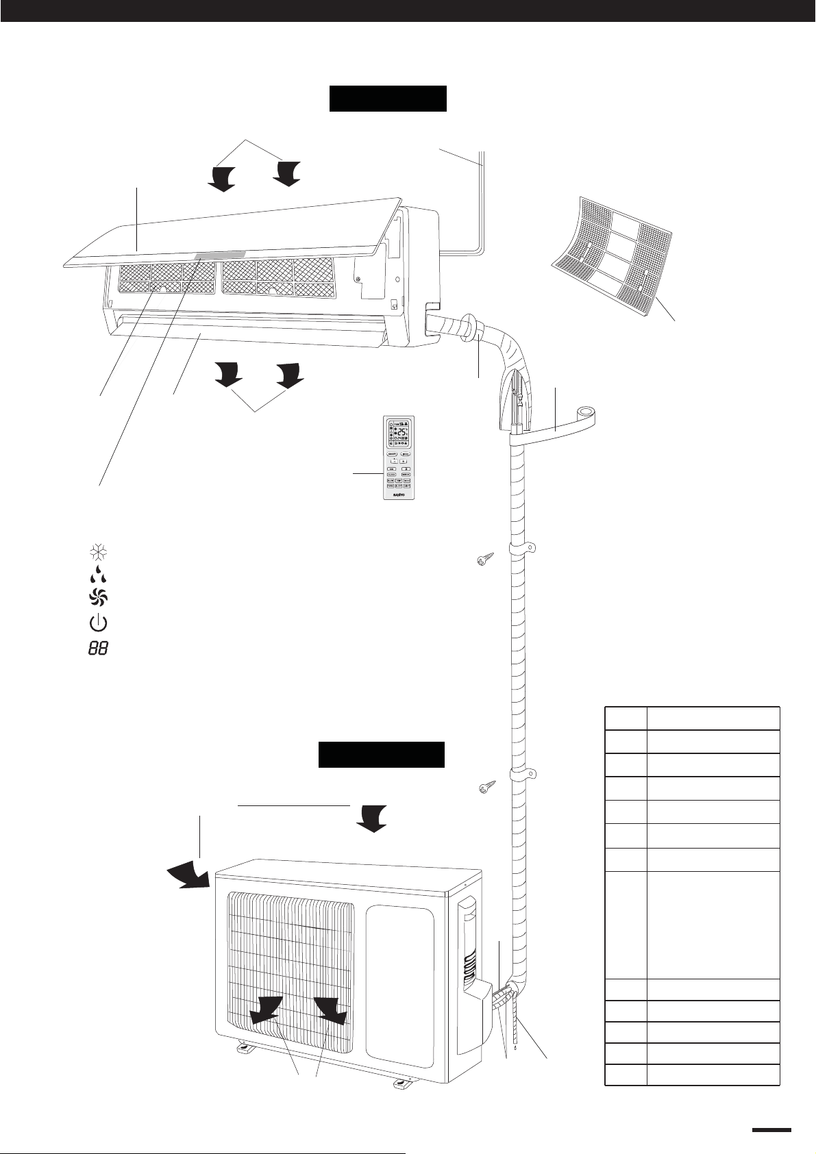
3. NAMES AND FUCTIONS OF EACH PART
Indoor Unit
Air intake
(1)
(3)
(8)
(4)
(5)
Air outlet
Back side
of part (4)
(9)
(6) (7)
The pattern in displayer:
:Cool
:Dry
:Fan
:Run
:Set temp.
Air inlet
(2)
Wireless
remote control
Outdoor Unit
art Name
1
2
(3
4
5
6)Receiver
7
ower
mot
ront Panel
t
uide Louver
n
tor
ontro
(10)
n
n
et Temp.
8
9)
10
11
(12)
Air outlet
(11)
12)
n
ape
onnection Wir
Drainage Pipe
onnection Pip
6
Page 9
Operation and Maintenance
4. OPERATION OF WIRELESS REMOTE CONTROL UNIT
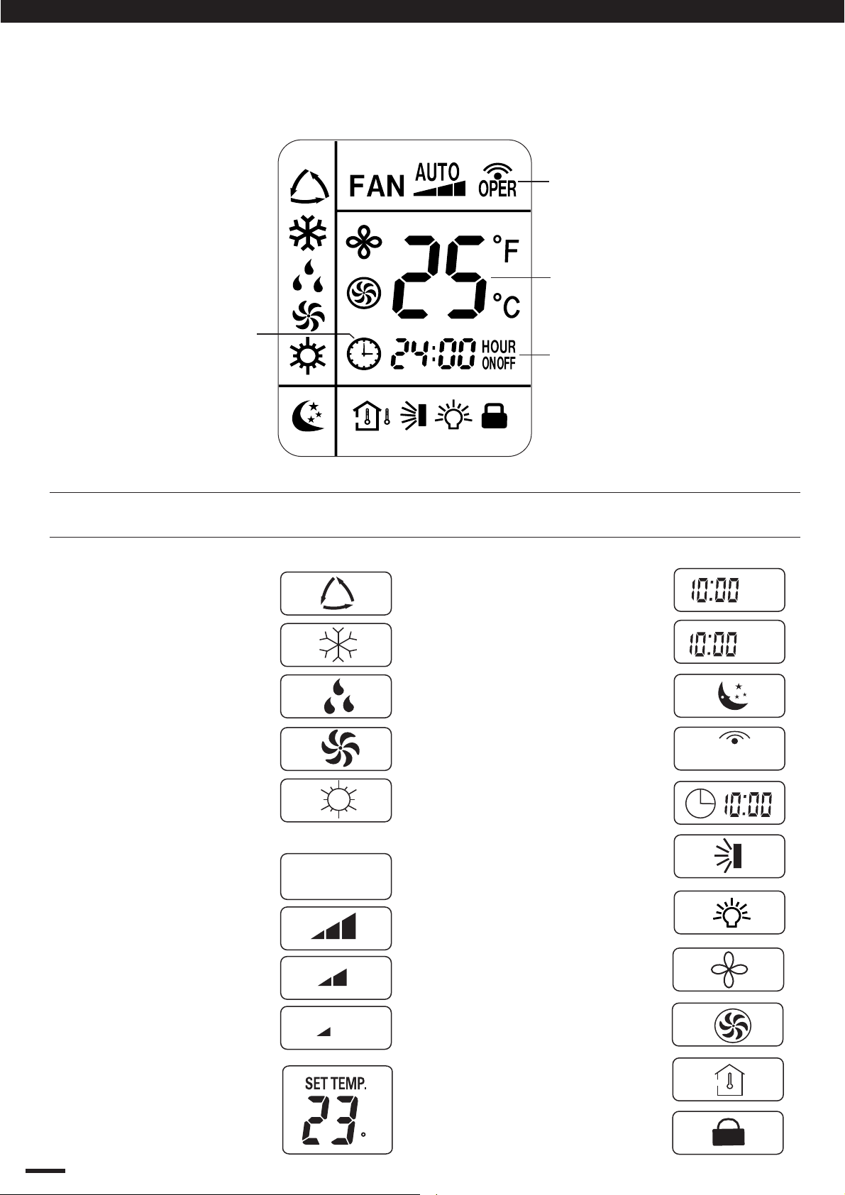
4.1 Remote Control Unit (Display)
Displayed when
transmitting data
Displayed when setting
temperature
Displayed the clock
(1) Operation mode
AUTO ..........................
COOL ..........................
DRY.......... ....................
FAN .............................
Symbols
(4) Timer
(5) Sleep ..............................
(6) Confirmation of ..............
transmission
Displayed when setting
timer
24-hour ON Timer .........
ON
24hour OFF Timer .........
OFF
OPER
HEAT ............................
(Not for cooling only model)
(2) Fan speed
Automatic operation .....
HIGH ............................
MID...............................
LOW ............................
(3) Set temperature
16 – 30 °C
When set to 23 °C ...
7
AUTO
C
(7) Clock indication ............
(8) Sweep indication ............
(9) Light .............................
(10) Blow .............................
(11) Turbo ...........................
(12) TEMP ...........................
(13) Lock ............................
Page 10
Operation and Maintenance
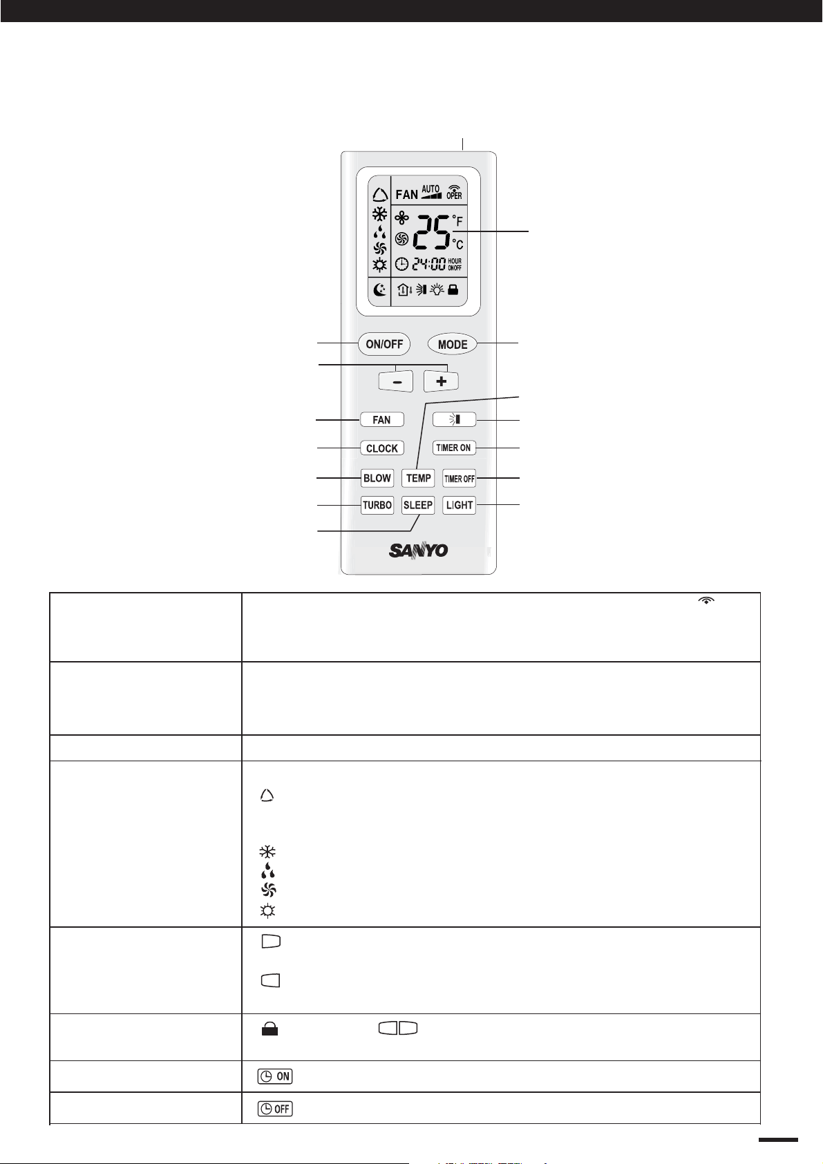
4. OPERATION OF WIRELESS REMOTE CONTROL UNIT
4.2 Remote Control Unit (Functions)
Signal Transmitter
Display
ON/OFF operation button
TEMP. setting button
FAN SPEED Selector button
CLOCK button
BLOW button
TURBO button
SLEEP button
Transmitter
Display
When you press the buttons on the remote control unit, the
mark appears in the display to transmit the setting changes to
the receiver in the air conditioner.
Information on the operating conditions is displayed while the
remote control unit is switched on. If the unit is turned off, only
CLOCK and TEMP was displayed.
MODE operation button
TEMP button
SWING button
TIMER ON button
TIMER OFF button
LIGHT button
OPER
ON/OFF operation
MODE selector button
(+) / (-) setting
buttons
LOCK / UNLOCK
button
TIMER ON button
TIMER OFF button
(AUTO)
(COOL)
(DRY)
(FAN)
(HEAT)
This button is for turning the air conditioner ON and OFF.
To select “AUTO” “COOL”, “DRY” or “FAN” mode.
: When choosed this setting, the air conditioner calculates
the difference between the thermostat setting and the room
temperature and to select suitable running method.
: The air conditioner makes the room cooler.
: The air conditioner reduces the humidity in the room.
: The air conditioner run the indoor fan only.
: NOT function for cooling only model.
+
: Press the (+) button to increase set temperature, continue
press 2 seconds for fast increasing set temperature.
-
: Press the (-) button to reduce set temperature, continue
press 2 seconds for fast reducing set temperature.
-
: Press the button at the same time to lock or unlock
wireless remote controller.
: The air conditioner starts at the set time.
: The air conditioner stops at the set time.
+
8
Page 11
Operation and Maintenance
4. OPERATION OF WIRELESS REMOTE CONTROL UNIT
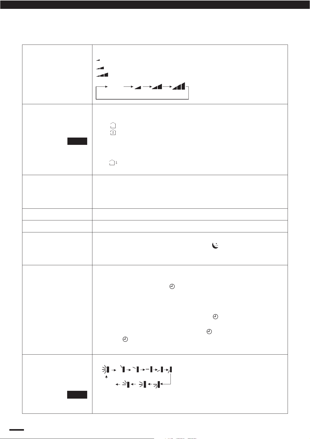
4.2 Remote Control Unit Functions (Continued)
FAN SPEED selector
button
TEMP button
NOTE
BLOW button
AUTO
: The air conditioner automatically decides the fan speeds.
: Low fan speed.
: Medium fan speed.
: High fan speed.
AUTO
Press to see set temperature or indoor temperature which show on
the indicator lamp according to customer requirement.
: Display the presetting temperature.
: Display the indoor ambient temperature (5 seconds)
It will display the ambient temperature for 5 seconds,
After 5s later, then will back to display the presetting
temperature.
: Current displaying status will not be changed.
No Icon : Default to display the pesetting temperature.
Press to begin or stop indoor fan from blowing indoor components
to dry. This function applicable to “COOL” & “DRY” mode only. In
“AUTO” & “FAN”, “BLOW” function can not be set up and there is
no “BLOW” displaying.
LIGHT button
TURBO button
SLEEP button
CLOCK Button
SWING Button
Press this button will turn ON / OFF the display of indicator light.
Press to quickly cool or heat the room with intense cool or hot air.
For details, see “SLEEP MODE” (P.g 12). When you press this
button in the“DRY” or “COOL” mode, the mark appears in the
display, and the remote control unit will automatically adjust the set
temperature to save energy.
Use this button to set the clock.
How it Works?
Press clock button, signal blink and display. Within 5 seconds,
the value can be adjusted by pressing “+” or “-” button, if press this
button continuously for 2 seconds and above, in every 0.5 seconds,
the value on ten place of Minute will be increased 1. During
blinking, repress the Clock button, signal will be constantly
displayed and it denotes the setting succeeded. After powered on,
12:00 is defaulted to display and signal will be displayed. If there
is signal be displayed that denotes the current time value is
Clock value, otherwise it is a Timer value.
To set the air swing direction which circurlarly change as:
OFF
NOTE
9
When the guide louver start to swing up and down, if turn off
the Swing, the air guide louver will stop at the current
position. (refer P.g 13 for more detail)
Page 12
Operation and Maintenance
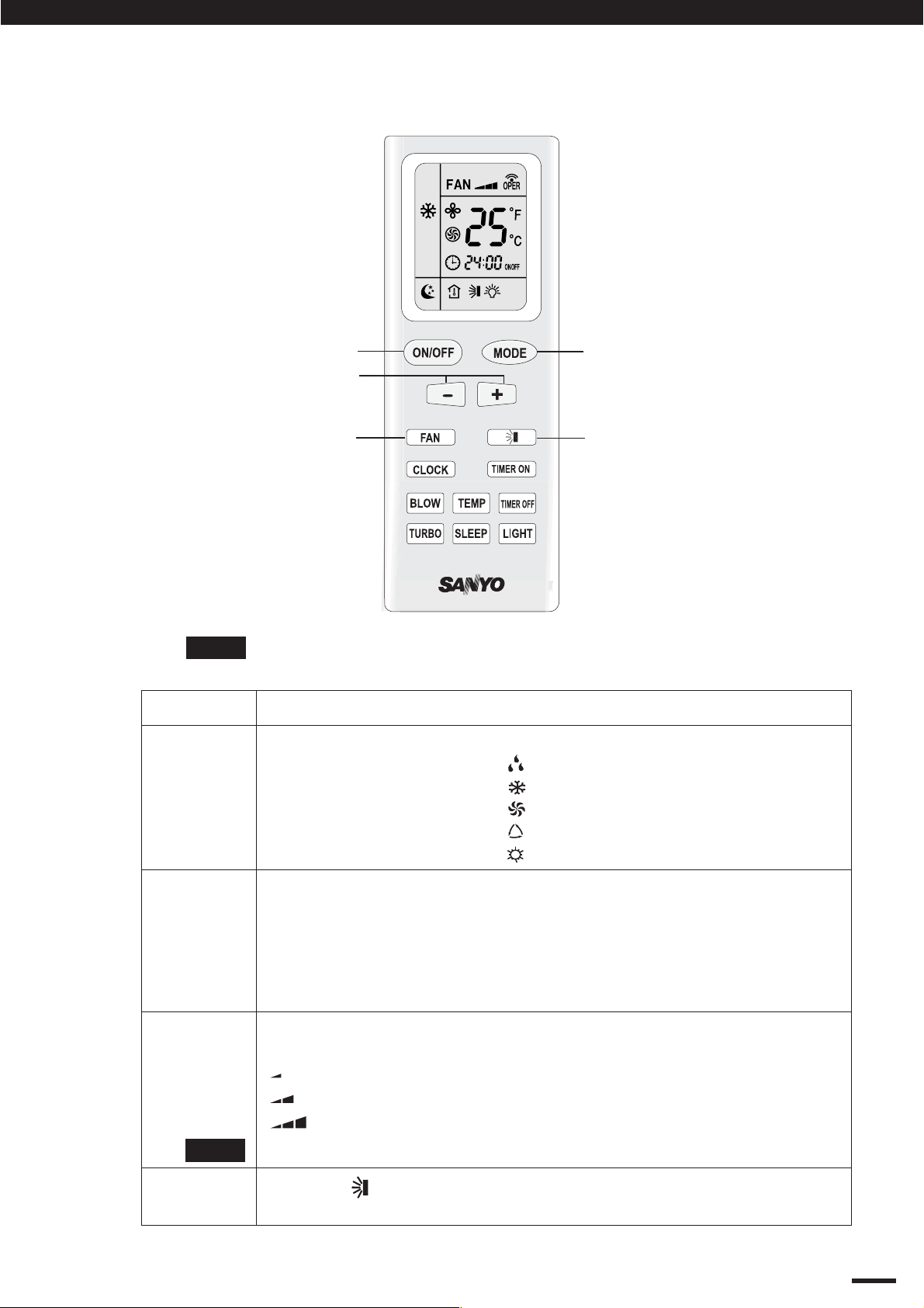
4. OPERATION OF WIRELESS REMOTE CONTROL UNIT
4.3 Using the General Operation
NOTE
STEP 1
STEP 2
STEP 1
STEP 3
STEP 4
Press the setting buttons as described below and change the settings
as desired.
To start the air conditioner, press the ON/OFF operation button.
Press the MODE selector button and select the desired mode.
For DRY operation
For COOLING operation
For FAN only operation
For AUTO operation
For HEATING operation
→
→
→
→
→
(Not function for cooling only model)
STEP 2
STEP 5
STEP 3
STEP 4
NOTE
STEP 5
Press the TEMP. setting buttons to change the temperature setting
to the desired temperature.
Adjustable temperature range:
30 °C (86 °F) max.—16 °C (61 °F) min.
Under “AUTO” operation, the temperature can not be adjust.
Under other operation, the initial value is 25 °C (77 °F).
Set the FAN SPEED selector button to the setting you want.
AUTO
Under Dry mode, the fan speed is automatically set to LOW.
Press the
automatically
To STOP the air conditioner, press the ON/OFF operation button again.
: Auto fan speed.
: Low fan speed.
: Middle fan speed.
: High fan speed.
button and set the air blow direction as desired or
.
10
Page 13

Operation and Maintenance
4. OPERATION OF WIRELESS REMOTE CONTROL UNIT
4.4 Using the 24-Hour “ON” or “OFF” Timer
4.4.1TIMER ON mode
(Example)
ON
After the length of time set for TIMER ON elapses, the unit
begins operating.
The display depicted at left indicates that the air conditioner will
begin operating in 10 hours.
Setting procedure:
STEP 1
Press the “ON/OFF” button and press “MODE”
button to set the desired operation mode. (See
“Operation with the Remote Control Unit”, Pg10).
Again, press the “ON/OFF” button to “OFF” the unit.
STEP 2
STEP 3
Press the “TIMER-ON” button.
Press the “T-ON” button (which advances the clock
displayed) to set the time at which you want
operation to begin.
The time can be set for 1 min. intervals for 24 hrs.
Hold pressing (+) / (-) button, it quickly change the
time value.
Press the “T-ON” button again to confirm the set
time is 10 A.M.
4.4.2 TIMER OFF mode
(Example)
OFF
The display changes immediately to CLOCK, but the
indication remains.
To check the status of the timer while it is counting down,
press the “TIMER-ON” button.
Cancellation Procedure : Press the “TIMER ON” button again
to cancel.
After the length of time set for TIMER OFF elapses, the unit
stops operating.
The display depicted at left indicates that the air conditioner will
stop operating in 10 A.M.
Setting procedure:
STEP 1
STEP 2
Press the TIMER OFF button.
Press the “T-OFF” button (which advances the clock
displayed) to set the time at which you want
operation to stop.
The time can be set for 1 min. intervals for 24 hrs.
Hold pressing (+) / (-) button, it quickly change the
time value.
Press the “T-OFF” button again to confirm the off
time is 10 A.M.
11
The display changes immediately to CLOCK, but the
indication remains.
To check the status of the timer while it is counting down,
press the “T-OFF” button.
Cancellation Procedure : Press the “TIMER OFF” button once
again.
Page 14

Operation and Maintenance
4. OPERATION OF WIRELESS REMOTE CONTROL UNIT
4.5 Using the SLEEP Operation
In Cooling and DRY
Mode : ( and )
SLEEP Mode is used for saving energy.
Press the SLEEP button while operation.
The mark appears in the display.
To release the SLEEP function, press the SLEEP button
again.
When the SLEEP mode is selected, the air conditioner
automatically rases the temperature setting 1 °C when 60
minutes have passed after the selection was made, and
then another 1 °C after another 60 minutes have passed,
regardless of the indoor temperature when SLEEP was
selected. Afterwards, the unit will remain this temperature.
This enables you to save energy without sacrificing comfort.
This function is convenient when gentle cooling is needed.
Setting
temperature
1 °C
1 °C
4.6 Using of the “Special”
Features
“DRY”
Operation
How it works?
“AUTO”
Operation
How it works?
Press the
SLEEP button
60 min.
Time60 min.
• While DRY operation, fan speed is automatically set to LOW.
• If the room temp. is 2 °C higher than the Set Temperature,
the unit will run in COOL mode.
• Once the room temp. reaches ± 2 °C of the level that was set,
the unit repeats the cycle of compressor turning “ON” 6 mins
and turning “OFF” 4 mins automatically.
• When AUTO mode is selected, the default temperature will be
displayed on the LCD, the unit will be in accordance with the
room temperature automatically to select the suitable running
method and to adjust ambient comfortable.
“BLOW”
Operation
How it works?
This function indicates that moisture on evaporator of indoor
unit will be blowed after the unit is stopped to avoid mould.
Once blow function is on, while the unit is off by pressing the
ON/OFF button, the indoor fan will continue running for about
10 min. at low speed. In this period, press “BLOW” button
again can stop indoor fan directly.
12
Page 15

Operation and Maintenance
4. OPERATION OF WIRELESS REMOTE CONTROL UNIT
4.6 Using of the “Special”
Features (Continued)
“TURBO”
How it works?
When setting the light function, the mark will display on the
remote controller screen by pressing this button. In which case,
the displayer indicator light will be on if the AC receives this
signal.
Operation
How it works?
“LIGHT”
Operation
How it works?
“LOCK”
Operation
How it works?
During “COOL” mode, if start this function, the unit will run at
super-high fan speed to cool quickly so that the ambient temp.
approachs the preset temp. as soon as possible.
It's a special selective button for the users , who are not
accustomed to the light at sleeping.
Setting “ON” the displayer indicator light
Setting “OFF ” the displayer indicator light
To cancel the light function, the mark will disapper on the
remote controller screen. In which case, the displayer indicator
light will be off if the unit receives this signal.
Press “+” and “-” buttons simultaneously to Lock / Unlock the
keyboard. If the remote controller is locked, the will be
displayed on it, inwhich case, press any button, the mark will
flicker for three times. If the keyboard is unlocked, the mark
will disappear.
“SWING”
Operation
How it works?
“ °F ” / “ °C ”
Operation
How it works?
About Swing Up and Down
1. Press swing up and down button continuously more than 2s,
the main unit will swing back and forth from up to down, and
then loosen the button, the unit will stop swinging and
present position of guide louver will be kept immediately.
2. Under swing up and down mode, when the status is
switched from off to , if press this button again 2s later,
status will switch to off status directly; if press this button
again within 2s,the change of swing status will depend on
the circulation sequence stated below:
OFF
About switch between Fahrenheit and Centigrade.
Under status of unit off, press “MODE” and “-” buttons
simultaneously and release both button immediately will switch
in °C and °F.
13
Power Failure
During Operation
How it works?
In the event of power failure, the unit will stop. When the power
is resumed, the unit will restart automatically after 3 minutes.
Page 16

Operation and Maintenance
4. OPERATION OF WIRELESS REMOTE CONTROL UNIT
4.7 How to Install Batteries
1. Slightly to press the place with , along the
arrowhead direction to push the back cover of
wireless remote control. (Fig. 1)
2. Take out the old batteries. (Fig. 1)
3. Insert two new AAA1.5V dry batteries, and pay
attention to the polarity. (Fig. 2)
4. Attach the back cover. (Fig. 2, procedure 4)
NOTE
• The batteries last about six months. Replace the
batteries when the remote control unit’s display
fails to light, or when the remote control cannot be
used to change the air conditioner’s settings.
• When changing the batteries, do not use the old
or different batteries, Use two fresh leak-proof type
-AAA alkaline batteries, otherwise, it can cause the
malfunction of the wireless remote control.
• If the wireless remote control will not be used for
more than one month, please take them out, and
don't let the leakage liquid damage the wireless
remote control.
• It should be placed at where is 1m away from the
TV set or stereo sound sets. If the wireless remote
control can not operate normally, please take
them out, after 30s later and reinsert, if they can’t
normally run, please change them.
• The remote control signal can be received at a
distance of up to about 4meter.
2
1
Fig. 1
3
4
Sketch map for
changing batteries
Fig. 2
(Indoor unit)
Air conditioner
4.8 Using the Remote Control Unit
When using the remote control unit, always point the
unit’s transmitter head directly at the air conditioner’s
receiver. (Fig. 3)
4.9 Emergency Operation
If the wireless remote control is lost or broken, please
use the manual switch button. At this time, the unit
will run at the “AUTO” mode, but the temperature and
fan speed cannot be changed. (Fig. 4)
To open the panel, the manual switch is located on
the displayer box. The operation was shown as below:
• Turn “ON” the Unit:
At unit turned off, press the button, the unit will run
at Auto mode immediately. The microcomputer will
accord to the indoor temperature to select (Cooling,
Heating or Fan) and obtain the comfortable effect.
• Turn “OFF” the Unit:
At unit turned on, press the button, the unit will stop
working.
Receiver
FAN
OPER
C
ON
SWING
AM
O
N
/
O
F
F
T
EM
M
P
-
F
T
A
EM
N
P
+
S
L
E
E
P
S
W
T
I
N
O
G
N
C
L
O
T
C
I
M
K
E
-
T
O
C
A
F
N
C
F
E
L
T
I
M
E
+
(Transmitter head)
O
D
E
Remote control unit
Fig. 3
Manual switch
Fig. 4
o
14
Page 17

Operation and Maintenance
5. CLEAN AND CARE
CAUTION
1. For safety, be sure to turn the air conditioner off
and also disconnect the power before cleaning.
Or it may cause electric shock.
2. Never sprinkle water on the indoor unit and the
outdoor unit for cleaning because it can cause an
electric shock.
3. Volatile liquid (e.g. thinner or gasoline) will
damage the air conditioner. (So wipe the units
with a dry soft cloth, or a cloth slightly moistened
with water or cleanser.)
5.1 Clean the Front Panel
(Make sure to take it off before cleaning)
Fig. 4a
1. Take off the front panel
Push in both ends of grooves to the shown position
beside at the same time by the arrow direction.
(Fig. 4a, 4b)
2. Washing
Clean with a soft brush, water and neutral detergent,
and then to dry it with a clean soft cloth. (Fig. 5)
NOTE
3. Put on front panel
Insert the supports on both ends of panel into groove,
and put the mid rotating shaft in groove, cover the
panel cover according to arrow direction and cover
well. (Fig. 6a,6b)
Do not use hot water which temperature
above 45°C to prevent fade or
deformation.
5.2 Cleaning the Air Filters
(Recommended once every 3 months)
NOTE
1. There are microcomputer components
and circuit diagram on the LCD of front
panel.
2. After taking off the filter, some metal
edges and the fins are sharp and may
cause injury if handled improperly; be
especially careful when you clean these
parts.
3. If dust is much more around the air
conditioner, the air filters should be
cleaned more often.
4. The internal coil and other components
of the outdoor unit must be cleaned
every year. Consult your dealer or
service center.
Fig. 4b
Fig. 5
Fig. 6a
Fig. 6b
15
Page 18

Operation and Maintenance
5. CLEAN AND CARE
5.2 Cleaning the Air Filters (Continued)
1. Take Down the Air Filters
Pull out the panel to an angle at botttom grooves on
panel. And, pull the air filter upward then downward
to take it off. (Fig. 7).
2. Cleaning
To clean the dust adhering to the filters, you can
either use a vacuum cleaner, or wash them with
warm water (the water with the neutral detergent
should below 45 C) when the filters are very dirty
(such asoil stain), and dry it in the shade. (Fig.8)
NOTE
3. Put back the filter
Put back the filter, then cover the surface panel well.
(Fig. 9)
Don't use hot water which temperature
is above 45°C to prevent fade or
deformation.
Don't dry it on fire for filter, it would
catch a fire or deformation.
o
5.3 Check Before You Use
1. Be sure that nothing obstructs the air outlet and
intake vents. (Fig.10)
2. Check that whether ground wire is properly
connected or not.
3. Check that whether the batteries of air conditioner
are changed or not.
4. Check that whether installation stand of the outdoor
unit is damaged or not. If damaged, please contact
the dealer.
Fig.7
air filter
Fig.8
Fig.9
5.4 Maintain After Use
1. Turn main power off.
2. Clean the filter, indoor and outdoor units' bodies.
3. Clear dust and obstructions from the outdoor unit.
4. Repaint the rubiginous place on the outdoor unit to
prevent it from spreading.
Fig.10
16
Page 19

Operation and Maintenance
6. TROUBLESHOOTING
CAUTION
Don't attempt to repair the air conditioner by yourself, it can cause an electric shock or fire.
Please check the following items before asking for repair, it can save your time and money.
gnitoohselbuorTnonemonehP
Dot not operate immediately when the air
conditioner is restarted.
Waiting
There's unusual smell blowing from the outlet
after operation is started.
Sound of water flow can be heard during
operation.
Once the air conditioner be restarted
immediately after turned off, overload
protect switch would make it will run after a 3
delay of minutes.
The unit has no peculiar smell by itself. If
happened, this is the smell accumulated in the
ambient.
Solution : Clean the air filters (see Pg.15).
If the problem still has, the unit required
servicing. Hence, please contact with SANYO
authorized maintenance center.
Sometimes there is swoosh, or gurgle while
the air conditioner is started, stopped or when
the compressor started or stopped running,
the sound is due to refrigerant flowing. They
are not malfunctions.
Creaking noise can be heard when start or
stop the unit.
,rehgih era ytidimuh dna .pmet roodni nehW.dettime si tsim ehT
sometimes this phenomenon will happen.
This is caused by the room air is swiftly cooled
down. After run for a while, indoor temp. and
humidity will fall down, the mist will die away.
This is caused by the deformation of plastic
due to the change of temperature.
17
Page 20

6. TROUBLESHOOTING
Operation and Maintenance
gnitoohselbuorTnonemonehP
The unit can not operate.
Breaking off
Cooling(Heating) efficiency is not good.
Remote control is not available.
• Has the power been shut down?
• Is the power plug loosed?
• Is voltage too high or too low?
(tested by professional)
•
Has the TIMER ON function been well
operated?
•
Is temperature setting suitable?
• Does inlet or outlet vents obstructed?
• Is filter dirty?
• Are the windows and doors closed?
• Did fan speed set at low speed?
• Is there any heat sources in the room?
• The unit is interfered by abnormal
interference or changing function too
frequently, wireless remote control can not
control occationally. Plug out power plug
and re-insert well could resume normal
operation.
• Is the control in the receiving area? Or is
there obstruction.
• Check if the voltage batteries in the control
is enough, if not, change batteries.
.
If water leakage in indoor unit.
If water leakage in outdoor unit.
Noise from indoor unit emitted.
Indoor unit can't deliver air.
Moisture on air outlet vent.
• The air humidity is on the high side.
• Condensing water over flowed.
• The indoor unit drainage pipe connection
loosed.
• When the unit is running in COOL mode,
the connection of pipe and pipe joint will
be condensed due to the water cooled
down.
• Fan or compressor relay switching
(On/OFF) sound.
•
In DRY “ ” mode, indoor fan sometimes
will stop, in order to avoid condensing
water be vaporized again, restrain
temperature raising
• If unit is running under the high humidity for
a long time, the moisture will be condensed
on the air outlet grill and drip off.
18
Page 21

Installation Service
7. NOTICES FOR INSTALLATION
Important Notices
7.1 Basic Requirements
for Installation
Position
1. The unit installation work must be done by qualified
personnel according to the local rules and this manual.
2. Before install, please contact with local authorized
maintenance center. If the unit is not installed by the
authorized maintenance center, the malfunction may
not solved, due to discommodious contacts.
3. When removing the unit to the other place, please
firstly contact with the authorized SANYO Maintenance
Center in the local area.
Install in the following place may cause malfunction. If it
is unavoidable contact with service center please:
1. Place where strong heat sources, vapors, flammable gas or
volatile object are emitted.
2. Place where high-frequency waves are generated by radio
equipment, welders and medical equipment.
3. Place where a lot of salinities such as coast exists.
4. Place where a sulfured gas such as the hot spring zones is
generate.
5. Place where the oil (machine oil) is contained in the air.
6. Other place with special circumstance.
7.2 Indoor Unit
Installation Position
Selection
7.3 Outdoor Unit
Installation
Position Selection
1. The air inlet and outlet vent should be far from the
obstruction, make sure that the air can be blown through
the whole room.
2. Select a position where the condensing water can be easily
drained out, and the places easily connected for outdoor
unit.
3. Select a location where the children can not reach.
4. Can select the place where is strong enough to withstand
the full weight and vibration of the unit. And will not increase
the noise.
5. Be sure to leave enough space to allow access for routine
maintenance. The height of installed location should be
200cm or more from the floor.6. Select a place about 1m or
more away from TVset or any other electric appliances.
7. Select a place where the filter can be easily taken out.
8. Make sure that the indoor unit installation should accord
with installation dimension diagram requirements. (Pg.24)
1. Select a location from which noise and outflow air emitted
by unit will not inconvenience neighbours, animals, plants.
2. Select a location with sufficient ventilation.
3. Select a location where there should be no obstructions
cover the inlet and outlet vent.
4. The location should be able to withstand the full weight and
vibration of the outdoor unit and permit safe installation.
5. Select a dry place, but do not expose under the direct
sunlight or strong wind.
19
Page 22

Installation Service
7. NOTICES FOR INSTALLATION
7.3 Outdoor Unit
Installation Position
Selection
(Continued)
7.4 Safety Requirements
for Electric
Appliances
6. Make sure that the outdoor unit installation dimension
should accord with installation dimension diagram,
convenient for maintenance, repair. ( See Pg.21)
7. The height difference of connecting the tubing & the max.
length of connecting tubing refer to Pg.31, Table 4.
8. Select a place where it is not reachable for the children.
9. Select a place where will not block the passage and do
not influence the city appearance.
1. The power supply should be used the rated voltage and
AC exclusive circuit, the power cable diameter should be
satisfied.
2. Voltage applying range: the normal running range is rated
voltage 198V - 264V.
3. Don't drag the power cable emphatically.
4. It should be reliable earthed and it should be connected to
the special earth device, the installation work should be
operated by the professional.
• The creepage protect switch and air switch with enough
capacity must be installed in the fixing circuit.
• Air switch (thermal-magnetic breaker) can protect the short
circuit and overload.
5. The min. distance from the unit and combustive surface is
1.5m.
7.5 Earthing
Requirements
7.6 Others
NOTE
1. Air conditioner is type 1 electric appliance, thus please do
conduct reliable earthing measure.
2. The yellow-green two-color wire in air conditioner is
earthing wire and cannot be used for other purpose. It
cannot be cut off and be fix it by screw, otherwise it would
cause electric shock.
3. The user power must offer the reliable earthing terminal.
DO NOT connect the earthing wire with the bellow places:
- Gas pipe
- Tap water pipe
- Contamination pipe
- Other places that the professional personnel consider
them unreliable.
1. The connection method of unit and power cable as well as
the interconnection method of each isolated component
should refer to the circuit diagram stick on the unit.
2. The model of the blown fuse and rated value should refer
to the silk-screen on the controller or fuse sleeve.
3. The outside static pressure is 0MPa when the unit is
testing.
• The power supply position should be
correctly connected, and that should be
reliably connected, no internal short circuit.
•
Wrong connection, may cause fire.
20
Page 23

Installation Service
8. INSTALLATION DIENSION DIAGRAM
Space to the ceiling
15cm
Above
Space to the wall
15cm Above
Space to the wall
300cm
Above
250
cm
Above
Air outlet side
Space to the floor
•
The dimensions of the space necessary for correct
installation of the appliance including the minimum
permissible distances to adjacent structures.
15cm Above
Models
Space to the obstruction
30cm Above
Space to the wall
200cm Above
Air outlet side
A
Outdoor Unit Installation Dimension (mm)
50cm Above
B
Air inlet side
30cm Above
Space to the wall
50cm Above
BA
682044PA9C-PAS
682045PA21C-PAS
243055PA81C-PAS
183065PA52C-PAS
378275PA03C-PAS
21
Page 24

9. INSTALL INDOOR UNIT
Installation Service
9.1 Install the Rear Panel
1. Always mount the rear panel horizontally.
Due to the water tray of indoor unit has been
been adopted the both-way drainage design,
the outlet of water tray should be adjusted
slightly down when installing, that is taking the
outlet of the water tray as the center of a circle,
the included angle between the evaporator and
level should be 0 or more, that is good for
condensing water drainage.
2. Fix the rear panel on the wall with screws.
(Where is pre-covered with plastic granula)
3. Be sure that the rear panel has been fixed
firmly enough to support the weight of an adult
of 60kg, further more, the weight should be
evenly shared by each screw.
9.2 Install the Piping Hole
1. Determine which side of the unit you should
make the hole for tubing and wiring.
(Fig.11,12)
2. Make the piping hole (Ф55 or Ф70) in the wall
at a slight downward slant to the outdoor side.
(Fig.13)
NOTE
3. Insert the piping-hole sleeve into the hole to
prevent the connection piping and wiring from
from being damaged when passing through
the hole.
• Before making the hole, check
carefully that no studs or pipes
are directly run behind the spot
to be cut.
• Also avoid areas where electrical
wiring or conduits are located.
Model: K30AP
Wall
Space
to the
wall
150mm
above
Left
φ70mm (Rear piping hole)
Mark on the
middle of it
180mm
Wall-Mounting Plate
Models: K18AP / K25AP
Wall
Space
to the
wall
150mm
above
Left
φ55/70mm (Rear piping hole)
Mark on the
middle of it
138mm
Models: K12AP
Wall
φ
55mm
Space
to the
wall
150mm
above
Mark on the
middle of it
130mm
Left
(Rear piping hole)
Models: K9AP
Wall
φ
55mm
Mark on the
middle of it
Space
to the
wall
35mm
150mm
above
Left
(Rear piping hole)
(Rear piping hole)
Fig.11
Left
tubing
Gradienter
251mm
50mm
90mm
(Rear piping hole) φ70mm
Gradienter
Space
184mm
to the
wall
150mm
above
50mm
60mm
(Rear piping hole) φ 55/70m
Gradienter
173mm
50mm
90mm
(Rear piping hole)
Gradienter
150mm
40mm
90mm
Space
to the
wall
150mm
above
φ
Space
to the
wall
150mm
above
Right
φ
55mm
Right
Wall
Right
55mm
Wall
Right-rear
tubing
(recommended)
Wall
Space
to the
wall
150mm
above
Right
Wall
9.3 Install the Water Drainage Pipe
1. Drainage hose must be placed at downward
slant downward slant for smooth drainage.
2. Do not wrench, bend or heave the drainage
hose or flood its end by water. (Fig.14)
3. The prolonged drainage hose should be
covered by heat insulation material when
through indoor.
Wrenched
Fig.14
Bent
Flooded
Left-rear
tubing
Fig.12
Indoor
Wall pipe
Hole Dia.
( K9AP, K12AP K18AP )
Ø 55mm
Fig.13
Right tubing
Outdoor
Seal pad
Ø55 / Ø70
Protection
sleeve pipe
Hole Dia.
( K25AP, K30AP )
Ø 70mm
22
Page 25

Installation Service
9. INSTALL INDOOR UNIT
9.4 Connect Indoor and Outdoor Electric Wire
1. The power wire and power connection wire are
supplied in factory in a fixed length. (Fig.15,16,17)
WARNING
To avoid the risk of fire hazard, do
consult your local dealer if additional
wire length is required.
2. Open the surface panel and remove the wiring
cover. (Fig.15,16,17)
3. Route the power connection wire from the back of
the indoor unit and pull it toward the front through
the wiring hole for connection.
4. Connect the interconnection cord to the terminal
block, and then fix the cord with wire clamp.
5. Re-assemble the clamp and wiring cover.
6. Re-cover the surface panel.
Power Supply Wire
(Fixed in unit 1.6m)
Wiring Cover
2
N(1)
Blue
Black
Power connection wire
to outdoor unit
Yellow-Green
(Factory supplied 5m)
Fig.15 (K9AP, K12AP)
WARNING
Since one end of power connector wire has
been connected in the unit, when testing unit
with electrified, the other end of the power
connect wire may carry electricity. Please note
to prepare well insulation to prevent short
circuit or electricity shock.
9.4.1 Wiring Instructions
NOTE General Precautions on Wirings
1. Before wiring, confirm the rated voltage of
the unit as shown in nameplate, then carry
out the wiring closely follow the wiring
diagram.
2. Provide a power outlet to be used exclusively
for each unit, with a power supply disconnect
and circuit breaker for overcurrent protection
provided in the exclusive line.
3. To prevent possible hazard due to insulation
failure, the unit must be grounded.
4. Each wiring connection must be done tightly
and in accordance with the wiring system
diagram. Wrong wiring may cause the unit to
misoperate or become damaged.
5. Do not allowed wiring to touch the refrigerant
tubing, compressor, or any moving parts of
the fan.
6. Unauthorised changes in the internal wiring
can be very dangerous.The manufacturer will
accept no responsibility for any damage or
misoperation that occurs as a result of such
unauthorised changes.
Power Supply Wire
(Fixed in unit 1.8m)
Wiring Cover
2
Black
3
Brown
Power connection wire
to outdoor unit
Yellow-Green
(Factory supplied 5m)
N(1)
Blue
Fig.16 (K18AP, K25AP)
Wiring Cover
2
Black
3
Brown
Power connection wire
to outdoor unit
Yellow-Green
(Factory supplied 5.5m)
N(1)
Blue
Fig.17 (K30AP)
23
Page 26

Installation Service
9. INSTALL INDOOR UNIT
9.4.2 Wire Length and Diameter
Regulations on wiring diameter differ from locality. For field wiring requirements, please refer to
local electrical codes. Carefully observe these regulations when carrrying out the installation.
Table 1 lists the recommended and max. allowable wire lengths and diameters for the power
supply system. Please refer to the wiring system diagram (Fig.18 & 19) for the meaning of “A”, “B”
in Table 1a,b,c,d.
Table 1a
Cross-sectional
area (mm2)
Model 1.0x (3)
KC9AP
Recommended
*(A)
1.6m 17m 10A
*(B)
1.0x (3) 1.0
5.0m
Max. allowed
(A) + (B)
Fuse or circuit
breaker capacity
Table 1b
Cross-sectional
area (mm2)
Model 1.5 x (3)
KC12AP
Recommended
*(A)
1.6m 22m 10A
*(B)
1.5 x (3) 1.5
5.0m
Max. allowed
(A) + (B)
Fuse or circuit
breaker capacity
Table 1c
Cross-sectional
area (mm2)
Model 2.5 x (3)
KC18AP 1.8m
KC25AP 1.8m
Recommended
*(A)
*(B)
2.5 x (4) 2.5
5.0m
Max. allowed
(A) + (B)
32m
32m
Fuse or Circuit
breaker capacity
20A
30A5.0m
Table 1d
Cross-sectional
area (mm2)
Model
KC30AP
*(A) Power supply wiring length (m) ; *(B) Power connection wire length (m)
Recommended
*(A)
4.0 x (3)
6.0m
1.0 x (4) 4.0
*(B)
5.5m
Max. allowed
(A)
*(B)
1.0 x (4)
20m 30A
32m
Fuse or circuit
breaker capacity
CAUTION
• Be sure to connect the power supply line to the
indoor unit as shown in the wiring diagram.
(a) Fig.18 (KC9AP, KC12AP, KC18AP, KC25AP)
The outdoor unit draws its power from the
indoor unit.
(b) Fig.19 (KC30AP)
The indoor unit draws its power from the
outdoor unit.
WARNING
• Be sure to comply with local codes on running
the wire from the indoor unit to the outdoor
unit (size of wire and wiring method, etc.).
• Each wire must be firmly connected.
• No wire should be allowed to touch refrigerant
tubing, the compressor, or any moving part.
WARNING
WIRING SYSTEM DIAGRAM
Models: KC9AP, KC12AP
OUTDOOR
UNIT
Terminal
N(1)
2
Blue
Black
Yellow-Green
(Grounding Line)
Power Supply
Single Phase
230VAC 60HZ
L
N
Grounding Line
Models: KC18AP, KC25AP
OUTDOOR
UNIT
Terminal
N(1)
2
Blue
Black
Brown
Yellow-Green
(Grounding Line)
Power Supply
Single Phase
230VAC 60HZ
L
N
Grounding Line
Fig. 18 Outdoor unit draws its power
from indoor unit.
INDOOR
UNIT
Terminal
N(1)
2
Model: KC30AP
Blue
Black
Brown
Yellow-Green
(Grounding Line)
Power Supply
Single Phase
230VAC 60HZ
N
L
Grounding Line
(B)
(A)
BN (BK)
BU (WH)
(B)
(A)
BN
BU
OUTDOOR
(B)
(A)
BU
BN
INDOOR
UNIT
Terminal
N(1)
2
L
N
P.C.B
INDOOR
UNIT
Terminal
N(1)
2
33
L
N
P.C.B
UNIT
Terminal
N(1)
2
33
N(4)
5
To avoid the risk of electric shock, each air
conditioner unit must be grounded.
Fig. 19 Indoor unit draws its power
from outdoor unit.
24
Page 27

9. INSTALL INDOOR UNIT
9.5 How to Install the Indoor Unit
For tubing, choose either the left side or right
side direction.
1. When routing the piping and wiring from the
left or right side of indoor unit, cut off the
tailing from the chassis in necessary.
(As shown in Fig 20)
•
Cut off the tailings 1 when routing the
wiring only.
•
Cut of the tailings 1 and tailings 2 when
routing both the wiring and piping.
2. Take out the piping from body case, wrap
the piping, electric wire, water pipe with
tape and push them through the piping hole.
(As show in Fig.21)
3. Hang the mounting slots of the indoor unit
on the upper tabs of the rear panel and
check if it is securely seated on the rear
panel. (As show in Fig.22)
Installation Service
Gas side piping
Gas side piping
insulation
Finally wrap
it with tape
Tailing 2
Tailing 1
Fig.20
External connection
electric wire
Liquid side piping
Liquid side piping
insulation
Water drainage
pipe
4. Carefully bend the tubing (if necesasry) to
run along the wall in the direction of outdoor
unit and then tape as far as the fittings.
(Refer 9.3 on Pg. 22). The drain hose should
come staright down the wall to a point where
water run off won't stain the wall.
5. Connect the refrigerant tubing to the outdoor
unit. (After performing a leak test on the
connecting part, insulate it with the tubing
insulation. (Fig.21) Also, refer to Pg 28,
(connecting tubing between indoor and
outdoor unit).
NOTE
For stable operation of the air
conditioner, do not install wallmounted type indoor units less than
2.5m from the floor level. (Fig.23)
CAUTION
Do not supply power to
unit or operate it until
all tubing and wiring to
the outside unit are
completed.
Risk of Electric Shock
Right
右后
Right rear
Fig.21
Fixing hook
Mounting
board
Fig. 22
Indoor unit
Minimum height
from floor level
2.5m
Left
Left rear
Mounting board
Wall
25
Floor level
Fig.23
Page 28

Installation Service
10. INSTALL OUTDOOR UNIT
10.1 Wiring Instructions for the Outdoor
Unit
Regulations on wire size differ from locality.
For field wiring requirements, please refer to
your local electrical codes. Make sure that
the installation fully complies with all local
and national regulations.
1. C9AP, C12AP, C18AP, C25AP
Disassemble the handle on the outdoor
unit right side plate. (Screw x 1pc)
C30AP
Disassemble the front side plate on the
outdoor front side. (Screw x 3pcs)
2. Take off wire clamp, connect and fix
power connect cord to terminal of line
bank. Connect the inter-unit wiring
and power line according to the
drawing on the handle (C9,12,18,25AP)
or front side plate (C30AP).
NOTE
Use the wire clamp to fix the
signal control wire, then
connect to the corresponding
connector.
Handle
Handle
Blue
Wire clamp
Black
Power
1.
Connection
Wire
2.
Yellow-green
Fig. 24a (C9AP,C12AP)
3
Blue
Black
Yellow-green
Brown
3. Fix the power connection cable with wire
clamp. (Fig. 24)
4. Be sure to size each wire allowing approx.
10 cm longer than the required length for
wiring, Store excess wiring inside the
cabinet.
5. When connections are completed, check
that all connections are correct as shown
in the wiring system diagram on the
handle / front side plate.
6. Be sure to ground the unit according to
your local codes.
7. Install back the handle / front side plate.
Front side
plate
WARNING
Loose wiring may cause the terminal to
overheat or result in unit malfunction.
A fire hazard may also exist. Therefore,
be sure all wiring is tightly connected.
Power
Connection
Wire clamp
1.
Wire
2.
Fig. 24b (C18AP, C25AP)
N(1)
Blue
Black
Power
Connection
Wire
3
N(4)
5
Blue
Brown
Wire clamp
Brown
Power
Supply
Wire
( Factory
supplied
6m )
Fig. 24c (C30AP)
Yellow-Green
26
Page 29

Installation Service
10. INSTALL OUTDOOR UNIT
10.2 Refrigerant Tubing
10.2.1 Use of The Flaring Method
Many of the conventional split system air
conditioners employ the flaring method to
connect refrigerant tubes which run between
indoor and outdoor units. In this method, the
copper tubes are flared at each end and
connected with flares nuts.
10.2.2 Flaring Procedure With A Flare Tool
•
Cut the copper tube to the required length
with a tube cutter. It is recommended to
cut approx. 30 - 50 cm longer than the
tubing length you estimate.
•
Remove burrs at the end of the copper
tube with a reamer or file. This procedure
is important and should be done carefully
to make a good flare. (Fig.25)
NOTE
When reaming, hold the tube end
downward and be sure that no
copper scraps fall into the tube.
(Fig.26)
Before
Deburring
After
Fig.25
Copper
tubing
Reamer
Fig.26
•
Remove the flare nut from the unit and be
sure to mount it on the copper tube.
•
Make a flare at the end of copper tube with
a flare tool.* (Fig.27)
(*Use "GRID" or equivalent.)
NOTE
10.2.3 Caution Before Connecting Tubes Tightly
•
Be sure to apply a sealing cap or water-
proof tape to prevent dust or water from
getting into the tubes before they are used.
•
Be sure to apply refrigerant lubricant to the
matching surfaces of the flare and union
before connecting them together. This is
effective for reducing gas leaks. (Fig.28)
•
For proper connection, align the union tube
and flare tube straight with each other, then
screw in the flare nut lightly at first to obtain
a smooth match. (Fig.29)
A good flare should have the
following charactcteristics:
- inside surface is glossy and
smooth.
- edge is smooth.
- tapered sides are of uniform
length.
Flare nut
Copper
Flare tool
Fig.27
Apply refrigerant
Iubricant here and here
Fig.28
Union
Fig.29
tubing
Flare nut
27
Page 30

Installation Service
10. INSTALL OUTDOOR UNIT
10.2.4 Connecting Tubing between Indoor and
Outdoor Units
•
Tightly connect the indoor side refrigerant
tubing extended from the wall with the outdoor
side tubing. (Fig. 30)
•
To fasten the flare nuts, apply specified torque
as table 2:
Table 2
Tube Dia. Tightening Torque
6.35 mm
9.52 mm
12.7 mm
15.88 mm
10.2.5 Insulation of Refrigerant Tubing
IMPORTANT
To prevent heat loss and wet floors due to
drippingof condensation, both tubes must be
well insulated with proper insulation material.
The thickness of the insulation should be a min.
8mm. (Fig. 31, 32)
CAUTION
Approx. 15 - 20 N.m (1.5 - 2.0 kg.m)
Approx. 35 - 40 N.m (3.5 - 4.0 kg.m)
Approx. 50 - 55 N.m (5.0 - 5.5 kg.m)
Approx. 68 - 82 N.m (6.8 - 8.2 kg.m)
Min.
8 mm
Indoor unit
Torque wrench
Spanner
Outdoor unit
Fig.30
Insulation
Fig.31
Insulation
Thickness:
min. 8 mm
After a tube has been insulated, never try to bend
it into a narrow curve, as this may cause to break
or crack.
10.2.6 Taping the Tubes
•
At this time, the 2 refrigerant tubes (and
electrical wire if codes permit) should be taped
together with armoring tape. The drain hose
may also be taped together as 1 bundle with
the tubing.
•
Wrap the armoring tape from the bottom of the
outdoor to the top of tubing where it enters the
wall. As you wrap the tubing, overlap half of
each previous tape turn. (Fig. 33)
Clamp tubing bundle to wall, using 1 clamp
•
approx. every 120cm.
NOTE
Do not wind the armoring tape too
tightly, since this will decrease the
heat insulation effect. Also, be sure
the condensation drain hose splits
away from the bundle and drips
clear of the unit and the tubing.
Fig.32
Clamp
Insulated tubes
Fig.33
Apply putty here
10.2.7 Finish the Installation
After finishing insulating and taping over the
tubing, use sealing putty to seal off the hole in
the wall to prevent rain and draft from entering.
(Fig. 34) shows refrigerant tubing taped
separately from the drain hose.
Tubing
Fig.34
28
Page 31

Installation Service
10. INSTALL OUTDOOR UNIT
10.3 Air Purging
Air and moisture remaining in the refrigerant
system have undersirable effects as indicated
below. Therefore, they must be purged
completely.
• Pressure in the system rises
• Operating current rises
• Cooling (or heating) efficiency drops
• Moisture in the air may freeze and block
capillary tubing.
• Water may lead to corrosion of parts in the
refrigerant system.
AIR PURGING WITH A VACUUM PUMP
(FOR TEST RUN)
1. Check that each tube (both narrow and wide
tubes) between the indoor and outdoor units
have been properly connected and all wiring
for the test run has been completed. Noted
that both narrow and wide tube service valves
on the outdoor unit are kept closed at this
stage.
Indoor unit
Outdoor unit
Manifold valve
2. Using a adjustable wrench or box wrench,
remove the valve caps from the service on
both narrow and wide tubes.
3. Connect a vacuum pump and a manifold
valve (with pressure gauges) to the service
port on the wide tube service valve. (Fig.35)
CAUTION
Be sure to use a manifold valve for air
purging. If it is not available, use a stop valve
for this pupose. The "Hi" knob of the
manifold valve must always be kept closed.
4. With the "Lo" knob of the manifold valve open,
run the vacuum pump. The operation time for
the vacuum pump varies with tubing length
and the capacity of the pump. The following
table shows the amount of time for evacuation:
Table 3
Required time for evacuation when
capacity of 100 liter/h vacuum pump is used
If tubing length is
less than 7 m
10 min. or more
If tubing length is
more than 7 m
15 min.or more
Pressure
gauge
NOTE
Lo
Hi
Vacuum pump
Fig.35
The require time in the table
3 is calculated based on the
assumption that the ideal
(or target) vacuum condition
is around 10 mmHg abs.
29
Page 32

Installation Service
10. INSTALL OUTDOOR UNIT
10.3 Air Purging - (Continued)
5. With the vacuum pump still running, close
the "Low" knob of the manifold valve. Then
stop the vacuum pump.
6. With the accessory hex wrench, turn the
valve stem on the narrow tube service valve
counter-clockwise by 90 degrees (1/4 turn)
for 10 seconds, and then turn the stem
clockwise to close it again. (Fig.36)
CAUTION
Be sure completely insert the hex
wrench before attempting to turn
the valve.
7. Leak test all joints at tubing (both indoor and
outdoor) with liquid soap. Bubbles indicate a
leak. Be sure to wipe off the soap with a
clean cloth.
8. WIth the hex wrench, turn the wide tube
service valve stem counter-clockwise to fully
open the valve.
o
90 (1/4 turn)
Valve Cap
Vacuum hose to manifold valve
Fig. 36
Narrow tube
Hex wrench
Wide tube
9. Turn the narrow tube service valve stem
counter- clockwise to fully open the valve.
10. Loosen the vacuum hose connected to the
wide tube service port slightly to release the
pressure. Then, remove the hose.
CAUTION
This may cause the refrigerant gas
to leak. In order to avoid this, take
off the hose quickly.
11. Fasten the valve cap on the wide tube
service port securely with an adjustable
wrench or box wrench. Next, mount the
valve cap on the service valve and
tightened it to 200 kg-cm with a torque
wrench. This process is very important to
prevent gas leaking from the system.
12. Test run the air conditioner. (See page 33)
15. Wipe off the soap on the tubing.
13. While the air conditioner is running, apply
liquid soap to check for any gas leaks
around the service valves or caps.
14. If there is no leakage, stop the air
conditioner.
This completes air purging with a
vacuum pump and the air conditioner is
ready for actual operation.
30
Page 33

Installation Service
10. INSTALL OUTDOOR UNIT
10.4 Tubing Length
Install unit within the maximum elevation
different (H) above or below the outdoor
unit and within a tatal tubing length (L)
from the outdoor unit as detailed showed
in Table 4 and Fig.37.
Table 4
Model
Max. Allowable Tubing
Length at Shipment
1
(m)*
Limit of Tubing
C9AP 5.0
C12AP 5.0
C18AP 5.0
C25AP 5.0
Length (L)
(m)
15
20
25
30
INDOOR
UNIT
Elevation
difference (H)
Limit of Elevation
Different (H)
(m)
5
5
7
7
Tubing length (L)
OUTDOOR
UNIT
Fig. 37
Required Amount of
Additional Refrigerant
(g/m)*
20
20
30
30
2
C30AP 5.0
*1 Standard tubing length is 5.0m.
*2 If total tubing length becomes 5.0m to 20 or 25 or 30m, charge additional refrigerant (R22) according
to table 4 above. No additional charge of compressor oil is necessary.
10.5 Accessories
Table 5 listed the accessories supplied with the unit.
Table 5
Parts Figure
Power
Connection
Wire
Tapping
Screw
Model:
K9AP,K12AP
4.2 x 25 mm
Models:
K18AP, K25AP, K30AP
30
Q’ty
1
5
10
15
50
Parts Figure Q’ty
AAA alkaline
battery
Flare Nut
Remote
Control Unit
*(K9AP, K12AP only)
OPER
FAN
0
C
ONOFF
TIMER OFF
MODE
TIMER ON
SLEEP LIGHT
- +
FAN
CLOCK
ON/OFF
BLOW TEMP
TURBO
2
1
1
31
Ins. Tube
Power
Supply
Wire
*(K30AP only)
1
Putty
1
Remote Control
1
Holder
1
(Optional)
*Only for specified model.
Page 34

11. PUMP DOWN
11.1 What is Pump Down?
Pump down means collecting all refrigerant gas
in system back into the outdoor unit without
losing any of gas. Pump down is used when the
unit is to be moved or before serving the
refrigerant circuit.
11.2 Pump Down Procedure
Installation Service
Indoor unit
NOTE
1. Connect the Lo side charging hose of the
manifold valve to the service port on the wide
tube service valve. (Fig 39)
2. Using a hex wrench, turn the narrow tube
service valve clockwise all the way to close
the service valve (Fig 40). (Be sure to confirm
that the wide tube service valve is fully open.)
3. Press the ON / OFF button and start cooling
operation.
4. When the low pressure gauge reading falls
from 1 to 0.5 kg/cm
tube valve stem (Fig 41). Then quickly stop
the unit.
5. Disconnect all gauges and hoses, and
replace the valve caps as they were before.
Be sure to carry out pump down
with the unit in cooling mode.
2
, fully close the wide
Manifold valve
Pressure
gauge
Lo
Outdoor unit
Hi
Narrow tube
Hex wrench
Wide tube
Valve Cap
Vacuum hose to manifold valve
Fig. 41
Fig. 39
Narrow tube
Hex wrench
Wide tube
Valve Cap
Vacuum hose to manifold valve
Fig. 40
32
Page 35

Installation Service
12. CHECK AFTER INSTALLATION AND TEST RUN
12.1 Check After Installation
Check the items listed in below table after installation of air conditioner.
Items to be checked Possible malfunction
• Has it been fixed firmly? • The unit may drop, shake or emit noise.
• Have you done the refrigerant leakage
test?
• Is heat insulation sufficient?
• Is the voltage in accordance with the rated
voltage marked on the nameplate?
• Is the electric wiring and piping connection
installed correctly and securely?
• Has the unit been connected to a secure
earth connection?
• Is the power cord specified?
• Is the inlet and outlet been covered?
• It may cause insufficient of cooling
capacity.
• It may cause condensation and dripping.
• It may cause condensation and dripping• Is water drainage well?
• It may cause electric malfunction or
damage the part.
• It may cause electrical leakage.
• It may cause electric malfunction or
damage the part
• It may cause electric malfunction or
damage the part
• It may cause of insufficient cooling
capacity.
• Has the length of connection pipes and
refrigerant capacity been recorded?
• The refrigerant capacity is not accurate.
12.2 Test Operation
12.2.1 Before Test Operation
• Do not switch on power before installation is finished completely
• Electric wiring must be connected correctly and securely.
• Cut-off valves of the connection pipes should be opened.
• All the impurities such as scraps and thrums must be cleared from the unit.
12.2.2 Test Operation Method
• Switch on power, press "ON / OFF" button on the wireless remote controller to start the
operation.
• Press MODE button, to select the “COOL”, “FAN” mode to check whether the operation is
normal or not.
33
Page 36

Installation Service
Error Code
(Indoor)
Diagnostics Item
Diagnostics contents
Models
F1
Indoor room
temperature sensor.
F2
Indoor heat exchanger
coil sensor.
• Sensor opens circuit or short circuit.
• Contact failure at connector.
• Indoor P.C.B failure.
C5
OTP data
(Jumper Cap).
• Jumper Cap on P.C.B failure.
• Indoor P.C.B failure.
K12AP,
K18AP,
K25AP,
K30AP.
H6
Indoor fan motor lock
current.
• Indoor fan motor failure.
If motor running speed is too slow /
stop for 1 min., in order to prevent
motor self-protection activated, it will
stop running and display lock.
• Contact failure at connector.
K12AP,
K18AP,
K25AP.
E5
Overload current
protection.
• Indoor P.C.B overload current
protector activated.
K18AP,
K25AP.
F3
Outdoor temperature
sensor.
• Outdoor dummy Sensor (R1) failure.
• Indoor / outdoor P.C.B failure.
K30AP
only
F4
Outdoor heat
exchanger sensor.
• Outdoor dummy Sensor (R 2) failure.
• Indoor / outdoor P.C.B failure.
K30AP
only
Table 6b. – ONLY for KC30AP.
Error Code
(Indoor)
Diagnostics Item
LED
(Outdoor)
Diagnostics Contents
E1
High pressure
protection.
Outdoor P.C.B
LED 1 blinking.
• High-pressure switch sensor
activated / failure.
E5
Overload current
protection.
Outdoor P.C.B
LED 2 blinking.
• Outdoor P.C.B overload current
protector activated.
E6
Communication signal
between indoor &
outdoor unit failure.
Outdoor P.C.B
LED 1, 2, 3
blinking.
• Indoor / Outdoor P.C.B failure.
• Wrong wirings connection.
• Wirings contact failure.
-
Communications signal
between Indoor &
outdoor unit normal.
Outdoor P.C.B
LED 4, 5 blink
alternately.
• It shows that the communication
signal is correctly under this
condition.
13. SELF DIAGNOSIS FUNCTION
13.1 What is self diagnosis function?
When the problem detected in the air conditioner, the operation stops and LED indicator lamps
on the indoor unit will display the error code (Fig. 42).
Kindly refer Table 6a,b for the meanings of error code and indications for each models.
Fig. 42
Table 6a
K9AP,
K9AP,
34
Page 37

SANYO Electric Co.,Ltd
 Loading...