


SANYO Home Appliance Division: 200 Riser Road Little Ferry, New Jersey 07643 REFERENCE NO. WM-17584
SANYO SPLIT SYSTEM AIR CONDITIONER SERVICE MANUAL
MODEL: SAP183KC
TABLE OF CONTENTS
| 1. | SPECIFICATIONS | 1 |
|---|---|---|
| 1-2 Major Component Specifications | 2 | |
| 1-3 Compressor Identification | 4 | |
| 2. | CONSTRUCTION OF THE UNIT | 5 |
| 3. | DIMENSIONAL DATA | . 6 |
| 4. | PERFORMANCE CHARTS | 8 |
| 5. | OPERATING INSTRUCTIONS | 10 |
| 6. | INSTALLATION INSTRUCTIONS | 12 |
| 7. | TROUBLESHOOTING | 24 |
| 8. | CHECKING AND REPLACING ELECTRICAL COMPONENTS | 35 |
| 9. | DISASSEMBLY AND SERVICE PROCEDURES | 44 |
| 10. | PARTS LIST | 57 |
| 1 1. | ន | |
| 12. | ELECTRIC WIRING DIAGRAM | 34 |
1. SPECIFICATIONS
1.1 Unit Specifications
| Model No. | SAP | 183KC | |||
|---|---|---|---|---|---|
| Unit Model No. |
Indoor Unit
Outdoor Unit |
SAI
SAI |
2183K
2183C |
||
| PERFORMANCE & ELECTRICAL | RATINGS | ||||
| Cooling Capacity | BTU/hr. | 18,000 | 0/17,600 | ||
| Moisture Removal (High) | Pints/hr. | 5.3 | 1/5.2 | ||
| Air Circulation (High) | Cu.ft min. | 562 | 5/530 | ||
| Energy Efficiency Ratio (EER) | BTU/hr. | 9.5 | 9.5/9.5 | ||
| Frequency | Hz | 10 | |||
| Rated Voltage | lated Voltage V | )/208 | |||
| Running Amps A | .8 | /9.2 | |||
| Power Input | W | 1,890 | /1,850 | ||
| Fuse (or Circuit Breaker) Capacity | / | 15 Am; | ≫s. 250 V | ||
| FEATURES | |||||
| Controls | Microcompute | Г | |||
| IC | 1 | /es | |||
| Fan Speeds | 2 | ||||
| Timer | |||||
| Ventilator | |||||
| Air Deflection Horizontal | Manuai | ||||
| Vertical | Manual | ||||
| Air Filter | Washable, | easy access | |||
| Temperature Control | IC The | rmostat | |||
| Compressor | Ro | tary | |||
| Refrigerant (R22) Ibs.(g | ibs.(g) | 4.08 (1,850) + 0.176 (80) for quick air purge | |||
| Refrigerant Tubing Connections | Flan | type | |||
| Refrigerant Line Length | Ft. (m) | 50 | (15) | ||
| Max. Outdoor Unit Height | Ft. (m) | 23 | (7) | ||
| Refrigerant Tube o.d. | Narrow Tube | In. (mm) | 1/4 ( | 6.35) | |
| Wide Tube | In. (mm) | 5/8 ( | 15.88) | ||
| Drain Pipe o.d. | in. (mm) | 1-1/32 | (26.2) | ||
| Refrigerant Tubing Kit | Optional | ||||
| DIMENSIONS & WEIGHT | IMENSIONS & WEIGHT | Indoor Unit | Outdoor Unit | ||
| Dimensions | Height | In.(mm) | 14-9/16 (370) | 24-13/16 (630) | |
| Width | In.(mm) | 49-7/32 (1,250) | 32-11/16 (830) | ||
| Depth | In.(mm) | 7-13/32 (188) | 12-13/32 (315) | ||
| Net Weight | ibs.(kg) | 50.6 (23) | 121.3 (55) | ||
| Shipping Size | ( | Cu.ft (cu.m) | 6.7 (0.19) | 10.59 (0.3) | |
| Shipping Weight | ibs.(kg) | 57.2 (26) | 132.3 (60) | ||
DATA SUBJECT TO CHANGE WITHOUT NOTICE.
1.2 Major Component Specifications
| UNIT MODEL No. | $AP183C | |
|---|---|---|
| COMPRESSOR | Harmetic Rotary Type | |
| Compressor Model No. | C-29130H6U | |
| Source | 230/208 V, 60 Hz, Single phase | |
| Pole | 2 | |
| Nominal Output (W) | 1,300 | |
| Displacement (cc/rev.) | 26.5 | |
| Amps-Full load (A) | B .8/8.3 | |
| -Locked Rotor (A) | 47/52 | |
| Type of Oil | Special Oil for Rotary Compressor | |
| Compressor Oil Amount ( | :c } | 800 |
|
Coil Resistance (Q)
(Ambient Temp. 77°) |
C-R: 1.15
C-S: 2.39 |
|
| Protective Device | Internal Line Break Overload Relay | |
| Run Capacitor | MFD | 30 |
| VAC | 370/400 |
| nit Model No. | SAP183K | SAP183C | |
|---|---|---|---|
| AN MOTOR | Capacitor-Run | Induction Motor | |
| Fan Motor Model No. | KFH4T-2186SP | $G65-51C6P | |
| Source | 230/208 V, 60 Hz, Single phase | ||
| Pole | 4 | 6 | |
| Nominal Output (W) | 20 | 50 | |
| Amps-Full Load (A) | 0.5/0.5 | 0.49/0.48 | |
| -Locked Rotor (A | A) | 0.59/0.53 | 0.80/0.67 |
| Protective Device | Internal Protector | ||
| 17AM035A5-4 | 9700K211-215 | ||
| Run Capacitor | MFD | 2 | |
| VAC | 4 | 10 | |
| Coil Resistance (Q) | - |
WHT-BRN 140.7
WHT-VLT 82.6 |
WHT-BRN 85.9
YEL-PNK 69.6 |
| (Ambient Te | mp 68°F) | VLT-PNK 93.7 | |
| Unit Model No. | SAP183C |
|---|---|
| OVERLOAD RELAY, COMPRESSOR | |
| OLR Model No. | Internal Type |
|
Temps Operating
- Reset |
293 ±9°F
189 ±20°F |
| Amps. at 77°F (Cold Start) | Operates within 6-16 sec. at 45 A |
| Amps. (Cold Start) | *Not operate for 30 min. at 13.5 A |
| Reset | Automatic |
*Reference value measure et 280°F
| UNIT MODEL No. | $AP183K |
|---|---|
| Transformer (for controller PCB) | ATR-J122U |
| Resistance (2) |
Primary: WHT-WHT 143.5
Secondary: BRN-BRN 1.2 |

d in the re trol unit
| Unit Model No. | SAP183K | |
|---|---|---|
| Room Temp. Sensor 41 | OCS5K | * |
| Resistance (kQ) | 69°F: 6-6.5, 86°F: 3.9-4.2, 77°F: 4.9-5.2 | |
| Unit Model No. | SAP183K |
|---|---|
| Dewproof Warmer | |
| Rating | 230 V, 13 W |

| Unit Model No. | SAP183C |
|---|---|
| Crankcase Heater | CH 5700 |
| Rating | 230 V, 30 W |

| Unit Model No. | 5AP183K |
|---|---|
| Freeze Protection Thermostat | RTB-4U301 |
| Operating Temperature | 50°F ON, 23°F OFF |
| Unit Model No. | SAP183C |
|---|---|
| Electro-Magnetic Contactor | CLK-16E3-21 |


1.3. Compressor Identification

3. Compressor Wire Orientation


2. CONSTRUCTION OF THE UNIT
INDOOR UNIT SAP183K

- 1. Air intake grille
-
2. Air filter (slide-out)
- Evaporator (= indoor heat exchanger)
- 4. Indoor fan
- 5. Electrical component box
- 6. Controller
- 7. Refrigerant tubing
- 8. Drain hose
- 9. Cabinet
- 10. Remote control unit
- 11. Air outlet grille
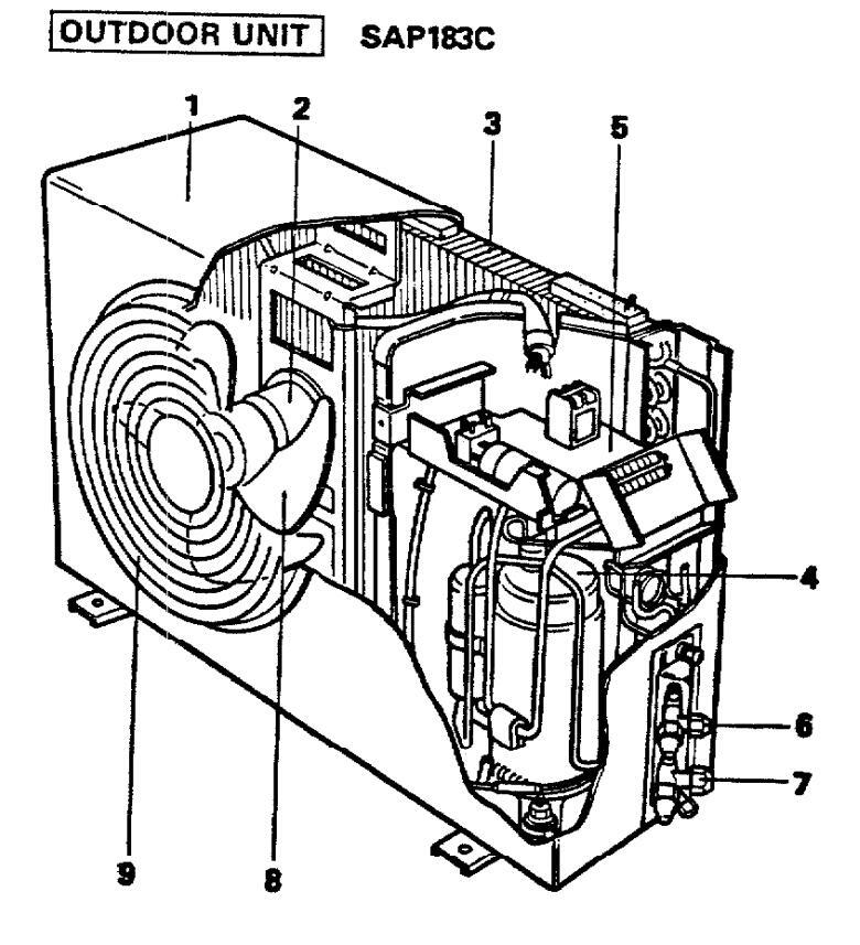
- 1. Cabinet
- 2. Fan motor
- 3. Condenser (= Outdoor heat exchanger)
- I. Compressor
- 5. Electrical component box
- 6. Service valve (Narrow tube)
- 7. Service valva (Wide tube)
- 8. Outdoor fan
- 9. Fan guard

3. DIMENSIONAL DATA
Outdoor Unit SAP183C

-7-
4. PERFORMANCE CHARTS
Cooling characteristics
Operating current characteristics versus outdoor embient temperature and indoor temperature (Indoor relative humidity: 50%, indoor air velocity: High, overall value for indoor and outdoor shown.)
Note: In low outdoor ambient temperature eress, the -outdoor fan is set automatically to Low.

Cooling characteristics
Operating current characteristics versus outdoor ambient temperature and indoor temperature (Indoor relative humidity: 50%, indoor air velocity: High, overall value for indoor and outdoor shown.)
Note: In low outdoor ambient temperature areas, the outdoor fan is set automatically to Low.

Cooling characteristics
Low pressure characteristics versus outdoor ambient temperature and indoor temperature (Indoor relative humidity: 50%, indoor air velocity: High.)
Note: In low outdoor ambient temperature areas, the soutdoor fan is set automatically to Low.

Cooling characteristics
High pressure characteristics versus outdoor ambient temperature and indoor temperature (Indoor relative humidity: 50%, Indoor air velocity: High.)
Note: In low outdoor ambient temperature areas, the outdoor fan is set automatically to Low.

5. OPERATING INSTRUCTIONS
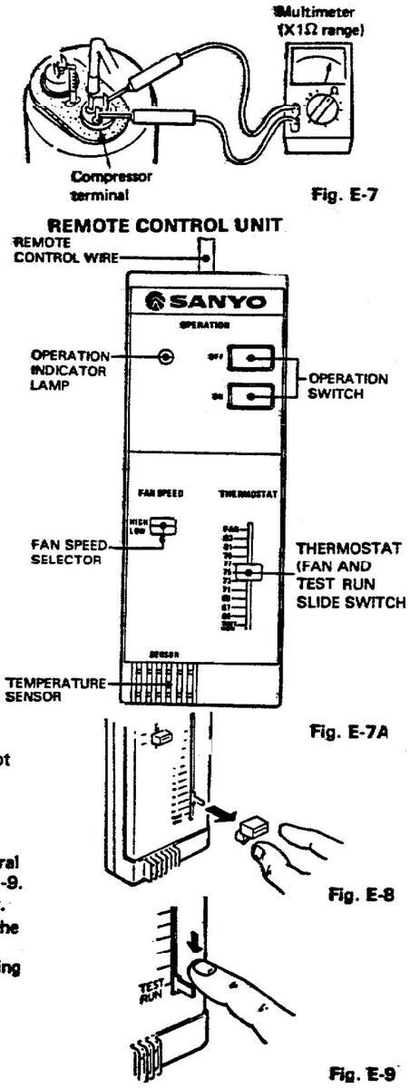
1. REMOTE CONTROL UNIT

A. REMOTE CONTROL WIRE
- B. OPERATION INDICATOR LAMP This temp will light when the operation button (ON) is pushed.
- C. FAN SPEED SELECTOR
- D. TEMPERATURE SENSOR Electronically senses the room temperature.
- E. OPERATION SWITCH See page 11 for how to operate.
- F. THERMOSTAT, FAN AND TEST RUN SLIDE SWITCH
OPERATION SWITCH
| SWITCH KIND OF OPERATION | OPERATION INDICATOR LAMP | |
|---|---|---|
| OFF | Stop of operation. | Operation lamp goes out. |
| ON Cooling operation takes place. | Operation lamp lights up. | |
• THERMOSTAT
The thermostat maintains the room temperature automatically at the desired level and ensures economical operation of the air conditioner. Just set the thermostat lever for the temperature level you want.
- NOTE: The numbers on the graduated scale are meant to serve as a guideline only. The actual room temperature may differ from the thermostat setting depending on room size and cooling load.
- FAN: Set thermostat lever to this position when FAN operation only is needed, without cooling.
- CAUTION: TEST RUN: This position is to be used only for test operation after completion of installation or during service operations. Normally it is locked.


2. HOW TO OPERATE
- 1) Turn on the power supply at least five hours before starting up the air conditioner.
- 2) Adjust the position of the thermostat lever.
- 3) Set the FAN SPEED selector to the desired speed
- 4) Press the ON pushbutton.
- HOW TO STOP Press the OFF pushbutton to stop the air conditioner.
- EMERGENCY SHUTDOWN
If the air conditioner does not stop even when the OFF pushbutton is pressed, turn off disconnect the power supply.

3. AIR FLOW DIRECTION
You can direct the air flow to the desired angle by moving the flap and vertical blades.
4. CAUTION
• SAFETY INTERVAL RESTARTING
After pressing the OFF button, the air conditioner stops and it will not restart for three minutes. To start the air conditioner again after three minutes, press the ON button.
• THERMOSTAT SETTING
Inadvertently moving the thermostat lever quickly up and down will cause the compressor to stop for three minutes.
Set the lever to the desired temperature and the unit will operate normally after three minutes.
. POWER SUPPLY
Be sure to supply power at least five (5) hours before operating the air conditioner at the beginning of the season. During the period of service, leave the power supply ON and let the current flow in the grankcase heater to warm up the compressor.
6. INSTALLATION INSTRUCTIONS
1. GENERAL
Here is a brief outline of where and how to install the unit. Please read over entire set of instructions for indoor and outdoor units and make sure all accessory parts listed are with the unit before beginning.
1-1. Tools Required for Installation (not supplied)
Drill, 3-5/32" dia. hole saw or key hole saw for normal walls. However, chisels or core bits will be required for brick, concrete, or similar walls.
- Common Screwdriver
- Phillips Head Screwdriver
- Knife or Wire Stripper
- Level
- Tape Measure
- Tube Cutter
- Flaring Tool
- Torque Wrench
- Adjustable Wrench
- Reamer or Small File
1-2. Accessories Supplied with Unit for Installation
| Pa | rts | Figure | Parts | Figure | Q'ty | |
|---|---|---|---|---|---|---|
| Wall fixture | 1 | Insul. Nipple | 1 | |||
|
Tapping
Screw |
Truss HD
Phillips 4 x 25 mm (1") |
20 |
Drain Pipe
Adaptor |
1 | ||
|
Mounting
Bracket |
For
Remote |
$ | 1 | Full Scale | ||
|
Tapping
Screw |
Control
Unit |
Flat HD
Phillips 3.1 x 13 mm (1/2") |
2 | Diagram | └─── | |
1-3. Optional Copper Tubing Kit
Copper tubing for connecting outdoor unit to indoor unit is available in kits which contain the narrow and wide tubing, fittings and insulation.
14. Type of Copper Tubes and Insulation Material
If you wish to purchase these materials separately from a local source, you will need:
Deoxidized annealed copper tube 1/4" outside dia. with a 0.0314" wall thickness, and an equal length of 5/8" outside dia. with a 0.0394" wall thickness.
Cut to the appropriate lengths + 12" to 20" on each to dampen vibration between units.
- Foamed insulation material 1/4" I.D., or 5/8" I.D. as required to precise length of copper tubing, wall thickness of insulation should be 5/6" to 1/2" thick. (Refer to page 20.)
- Copper Wire Inter Unit: Min. AWG 14 in appropriate length. Power Supply: Min. AWG 12 in appropriate length.
- 3" O.D. (I.D. 2-13/16", wall thickness 3/16") PVC pipe length to match thickness of wall.
- 1-5. Additional Materials Required to Give Installation a Professional Appearance
| Refrigeration (armored) tape | Refrigeration Oil |
|---|---|
|
|
| • Putty |
2. INSTALLATION SITE SELECTION
Indoor Unit
AVOID: • areas where leakage of flammable gas may be expected.
- places where large amounts of oil mist exist.
- direct sunlight.
- nearby heat sources that may affect performance of the unit.
- locations where remote control will be splashed with water or affected by dampness or humidity.
- installing remote control unit behind curtains or furniture that obstruct air circulation.
select an appropriate position from which every corner of the room can be uniformly air-conditioned. (High on the wall is best.)
- select a location that will hold the weight of the unit.
- select a location where tubing and drain pipe have shortest run to the outside.
- allow room for operation and maintenance as well as unrestricted air flow around the unit. See Fig. 1
- allow room for mounting control unit about 4' off the floor, in an area that is not in direct sunlight or in the flow of cold (or hot) air from the unit.
- install unit within 23' up or down of outdoor unit and within a total of 50' from outdoor unit. Fig. 2


Fig. 2
Outdoor Unit
-
AVOID: heat sources, exhaust fans, etc., Fig. 3 • direct sunlight.
- damp, humid or uneven locations.
- DO:
- choose a place as cool as possible. choose a place that is well ventilated and outside air temperature does not exceed 113°F constantly.
- allow enough room around unit for air intake/exhaust and possible maintenance. Fig. 4
- provide a solid base; concrete (concrete block, 4" x 4" beams or equal), about 4" above ground level to reduce humidity and possible water damage in unit and decrease service life. Fig.5
- use lag bolts or equal to bolt down unit, reducing vibration and noise.


3. HOW TO INSTALL INDOOR UNIT
3-1. Make a Hole
- a) Tape full scale installation diagram on wall at location selected, make sure unit is horizontal, use a level or tape measure to measure down from ceiling. Fig. 6
- b) Use a hammer and a finishing nail (gypsum or paneled wall) to tap tiny holes in the plan where pipe cut out is indicated to make sure wooden studs or pipes are not directly behind area to be cut out.

Also avoid area where piping goes through wall in any other location.

c) Using the hammer and nail method accross the diagram, you can find the studs in the wall (usually 16" apart) to assure a strong base for hanging the unit, put a pencil mark over the diagram at each stud location.
- d) Using a hole saw 3-5/32" dia. or key hole saw, cut a hole in inside wall, Fig. 7
- e) Cut and move insulation in wall away from opening and drill a pilot hole 1/8" dia. at a slight downward angle through the outer wall, using the hole saw or key hole saw, cut a hole in the outer wall from the outside. (For concrete, brick plaster or similar type walls appropriate tools will have to be used.)
- f) Measure thickness of wall from inside edge to outside edge and cut PVC pipe at a slight angle. Fig. 8
g) Insert PVC pipe in wall. Fig. 9

Fig. 9
3-2. Mount the Wall Fixture
Mount the wall fixture to match the holes shown on the Full-Scale Diagram Panel, Fig. 10 and Fig. 11
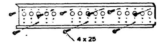

For a wooden wall, mount the fixture using the furnished 9 screws.
For a concrete wall, mount the fixture using commercially available 3 anchors.

* When using bolt anchors, the projection of the threaded section must not be more than 1/2 in. from the wall,
-
3-3. Wiring Instruction for Interunit Connections
-
a) Insert the interunit wiring (according to local codes) into through-the-wall PVC pipe. Run the wiring toward indoor side allowing approx. 3 in, from the wall face. Fig. 12
- CAUTION : Never fix the wiring by any means before the indoor unit is fully seated on the rear panel.
- b) Unscrew 6 screws and slide out the cabinet. Fig. 13
- c) Unscrew the cover plate of the electrical component box. Fig. 14
- d) Insert the wrapped tubing into the hole on the wall. Temporarily set the wiring connector in the hole at the electrical component box.
- e) Hang the unit on the wall fixture. Fig. 15
-
a) Insert the interunit wiring (according to local codes) into through-the-wall PVC pipe. Run the wiring toward indoor side allowing approx. 3 in, from the wall face. Fig. 12


Fig. 14
f) Secure the conduit connector to the electrical component box with a lock nut. Fig. 16


-- 16--

al Give some play to the interunit wiring from the outdoor unit to the corresponding terminals on the terminal base.
CAUTION :
- · Be sure to refer to the wiring system diagram label on the electrical component box and carry out correct field wiring. Wrong wiring causes malfunction of the unit.
- Check local electrical codes and also any specific wiring instructions or limitation.
3-4. Drain Piping
- a) Drain piping should be slanted downward to outdoor. Fig. 17
- b) Never form a trap in the course of piping.
-
c) If the drain pipe will run in the room, insulate the pipe with an insulation material" so that chilled condensation should not damage furniture or floors. Fig. 18
- * Foamed polvethviene or equivalent is recommended.
3-5 Install the Control Unit
Mounting position of control unit should be located in an accessible place for control and enable the average room temperature to be detected. Never cover over the unit or recess it into the wall.
a) Fix the mounting plate on the wall with 2 screws, align the rail on the rear of the control unit and slide the unit down as far as it will go. Fig. 19
b) Fix the cord to the wall.
CAUTION • The remote control unit has a temperature sensing element. Do not install it where:
- * Direct stream of cold (or hot) air can reach it.
- * Direct sunlight will fall on it.
- * There are obstacles such as counters and tables
- * Water vapor or moisture (of restaurants, etc.) is always present.
- * There is a door and outdoor air can reach it
- Do not twist the cord of the remote control unit and other power cables together. Otherwise the switch may malfunction

WARNING Do not supply power to the unit or operate until tubing and wiring to the outside unit is completed


4. HOW TO INSTALL OUTDOOR UNIT
Place unit on level pad, blocks or equal and anchor.
Refer to INSTALLATION SITE LOCATION given in page 14.
-
4-1. Wiring Instructions on Outdoor Unit
- a) To remove the access panel, remove 5 screws.
- b) Dismount plugs on the conduit plate.
- c) Temporarily mount conduit tubes on the conduit plate.
- d) Properly connect both power supply and interunit lines to corresponding terminals on the terminal block. Refer to the wiring diagram in Fig. 21, which is labelled on the access panel.
- e) Ground unit in accordance with local codes.
- f) Be sure to size each wire allowing several inches longer than the required length for wiring.
- g) Fasten lock nuts to secure conduit tubes.
CAUTION :
- Be sure to comply with local codes on running the wire from the indoor unit to outdoor unit. (size of wire and wiring method etc.)
- Every wire must be connected firmly.
- No wire should touch refrigerant tubing, compressor or any moving part.
CONNECTOR TRADE SIZE
| MODEL | POWER LINE | INTERUNIT LINE |
|---|---|---|
| SAP183KC | 1/2" | 1/2" |

WIRING SYSTEM DIAGRAM

Fig. 21
5. REFRIGERANT TUBING
5-1. Use of the Flaring Method
The refrioerant tubing for every split type air conditioner must be connected by flaring. In this method, the cooper tubes are flared at each end and connected with flare nuts.
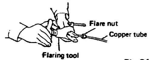
5-2. Flaring procedure with a Flaring Tool
- a) Cut the cooper tube to proper length with a tube cutter. It is recommended to cut approx, 12 ~ 20 in, longer than the estimated tubing length
- b) Remove burrs at the end of the copper tube with a reamer or a file. This process is important and should be done carefully to make a good flare. Fig. 22

NOTE : When rearning, hold the copper tube end downward and be sure that no copper scraps fall into the tube. Fig. 23
d) Make a flare at the end of copper tube with a flaring tool*. Fig.24 (*Use "RIGID" or equivalent.)
NOTA : Good flare should have following conditions:
- Inside surface is glossy and smooth.
- Edge is smooth.
- Tapered sides are in uniform length.
5-3. Caution before connecting tubes tightly
- a) Be sure to apply blind cap or water proof tape to prevent dust or water from getting into the copper tube, until it is used.
- b) Be sure to apply refrigeration oil to the matching surfaces of flare and union before connecting them together. This is effective for reducing gas leaks. Fig. 25
- c) For proper connection, hold the tube with union and the flared tube straight with each other, screw in the flare nut lightly at first to obtain smooth match. Fig. 26


Fia. 25

Fig. 26
c) Remove the flare nut from the unit and be sure to mount it on the copper tube.
5-4. Connecting Tubes between Indoor and Outdoor Units
- 1. Connect the indoor side refrigerant tubing extended from the wall with the outdoor side tubing tightly.
- 2. Flare nut on large dia. tube should be torqued to 510 ~ 550 lb in. Flare nut small dia. tube should be torqued to 130 ~ 170 lb in. Fig. 27
- 3. After performing a leak test on the connecting part, insulate it with INSUL. NIPPLE and finish with a vinyl masking tape over it. Fig. 28
- CAUTION: Never connect up tubes by brazing them. If it is inevitable, be sure to blow nitrogen gas while brazing to avoid oxidation of inside copper tube.
5-5. Insulation of Refrigerant Tubing
Because the capillary tube is installed in the outdoor unit, both wide and narrow tubes of this air conditioner become cold. Therefore, to prevent heat loss and wet floors due to dripping of condensation, both tubes must be well insulated with proper insulation material. Thickness of insulation material should be min. 5/16", Fig. 29
Insulation material
The material must of course have good insulation characteristics, be easy to use, age resistant, and must not easily absorb moisture. The following is recommended; foamed polyethylene or equivalent.
5-6. Taping the Tubes
- a) At this time, the two refrigerant tubes (and electrical wire if code permits) should be taped together with armoring tape. The drain pipe may also be included and taped together as one bundle with the tubing.
- b) Wrap the armoring tape from the bottom of the outdoor unit to the top of the tubing, where it enters the wall. As you wrap the tubing cover half of each previous tape turn. Fig. 30
- c) Clamp tubing bundle to wall, one clamp every 4' approx.
- NOTE : Do not wind the armoring tape around too tightly since this will impair the heat insulation effect. Also be sure condensation drain hose splits away from bundle.
5-7. Finishing the Installation
After finishing insulation and taping over tubing, fill the void space with putty to prevent rain and draft from entering. Fig. 31

Fig. 27

Fig. 28


Fig. 30

6 AIR PURCING
Air does not function as a refrigerant, because it cannot be liquefied in the condenser. Air and moisture remaining in the refrigerant system have undesirable effects as indicated at right. Therefore they must be purged completely.
TUBING DIAGRAM FOR AIR PURGING
- The pressure in the system rises.
- The operating current rises.
- Cooling and heating efficiency drops
- Water contained in the air may freeze and block the capillary tubing
- Water may lead to corrosion of parts in the refrigerant circuit.
Inadequate refrigerant charge may cause freeze-up problem of the evaporator. Follow the CANTION correct air purging procedures and be sure not to overbleed refrigerant.
6.1 Duick Air Purne System
New quick air purge system represents purging the air in the indoor unit and connection tub with the aid of refrigerant has precharged in the outdoor unit
In this system, air purging has become much simpler and installation time has become shorter than conventional methods.
- * Interval required for air purging is only 20 records
- NOIS: Outdoor unit is pre-charged at the factory. Don't open valves until tubing is
hooked up and you are ready to proceed with purging procedure.
6-2 Air Purging Procedure
- a) Remove the valve caps from the service valves on the narrow and wide tubes.
- b) Slacken off the flare nut at the charging port one full turn. Fig. 33
- c) Open the service valve on the narrow tube by 90 degrees (1/4 turn).
- (During this operation, air will be discharged from the charging port of the service valve on the wide tube.)
- d) 30 seconds after opening the spindle, properly tighten up the flare nut of the charging port.


* Check port is provided for measuring system pressure with a pressure gauge or the like during service.
- e) Shut the spindle of the service valve on the narrow tube. Fig. 34
- f) Leak test the joints with liquid soap. Fig. 35 g) Fully open the spindles of the service valves on the wide tube and the narrow tube.
- h) Next, install a valve cap in which coppe
- gasket has been inserted. Fig. 36 Here, all air purge procedure has completed and the unit is ready for trial operation.

-21--
SERVICE VALVE CONSTRUCTION
• Valve Position -a-
The valve spindles of both wide & narrow tubes are turned all the way in. The unit is shipped from the factory in this position. Fig. 37-a
• Valve Position -b-
The valve spindles of both wide & narrow tubes are turned all the way out ("BACK SEAT" position). This is the normal operating position. Fig. 37-b
• Valve Position -c-
With the narrow tube valve kept at BACK SEAT, only the wide tube valve spindle is turned halfway-down position. This position is used for pressure measurement and gas charging. Fig. 37-c
Valve Position -d-
Like position -a-, but with the flare nut of wide tube open. This position is used for air purging. Fig. 37-d


PUMP DOWN
Pump down means collecting all refrigerant in the system back into the outdoor unit without losing refrigerant gas. Pump down is used when unit is moved or for servicing the refrigerant circuit.
- 1) Close valve on wide tube halfway (2 turns).
- 2) Close valve on narrow tube all the way (4 turns).
- 3) Turn unit on (cooling) for approximately 3 minutes then shut off.
- 4) Close valve on wide tube all the way (2 additional turns).
- 5) Disconnect tubes slowly allowing pressure to equalize inside and out.
- 6) When tubing is disconnected provide dust covers for both valves and tubes until unit is reconnected.
7. PRECAUTIONS BEFORE STARTING
After insulation, be sure to bind up insulation material and refrigerant tubings with a water-proof tape so as rain should not creep into the insulation material and wiring.
- Before attempting to start the air conditioner, check the following:
- a) All loose matter is removed from the cabinet especially steel fillings and chips.
- b) Contro! wirings are correctly connected and all electrical connections tight.
- c) Check to see if compressor fixing bolts (3 pcs), which secure compressor during transportation, are screwed-in as in Fig. 39. If not, screw them in.
- d) Be sure to confirm that all shut-off valves are open.
- e) Power connected to unit for at least five hours before starting the compressor. The bottom of compressor should be warm to the touch and crankcase heater around the feet of the compressor should be hot to the touch.


Fig. 39
8. TRIAL RUN
Check that all tubing and wiring have been completed correctly. Check again that wide and narrow tube service valves are fully opened. Turn on power and run the unit.
NOTE :
If the room temperature is too low, cooling operation may not be possible even if the thermostat knob is set at the lowest position.
In this event, perform test run as follows:
- a) Pull off the thermostat knob. Fig. 40
- b) Set the thermostat lever to the lowest position. (The central position of the lever becomes the TEST RUN position.) Fig. 41
- c) Press OPERATION "ON" button to start the air conditioner.
- d) After completion of test run, press "OFF" button to stop the unit.
- e) Reinstall the thermostat knob. (The stopper position facing down.)

Fig. 41
7. TROUBLESHOOTING
| - Quick Access Index - Page | |
|---|---|
| 1. Ai | r conditioner does not operate |
| 1.1. | Circuit breaker trips (or fuse blows) |
| 1.1.1. | When circuit breaker is set to ON, it trips soon (Resetting is not possible) |
| 1.1.2. | Circuit breaker trips when the operation switch is depressed |
| 1.2. | Neither indoor unit nor outdoor unit runs |
| 2. So | me part of air conditioner does not operate |
| 2.1 | Indoor fan does not run |
| 2.2. | Neither outdoor fan nor compressor runs |
| 2.3. | Only outdoor fan does not run |
| 2.4. | Only compressor does not run |
| 2.5. | Compressor frequently repeats ON and OFF |
| 3. Aiı | conditioner operates, but abnormalities are observed |
| 3.1. | Poor cooling |
| ว ว | Excessive cooling |

1.1 Circuit breaker trips (or fuse blows)
1.1.1 When circuit breaker is set to ON, it trips soon (Resetting is not possible)

1.1.2 Circuit breaker trips when the operation switch is depressed.

1.2 Neither indoor unit nor outdoor unit runs

2. Some part of air conditioner does not operate
2.1 Indoor fan does not run

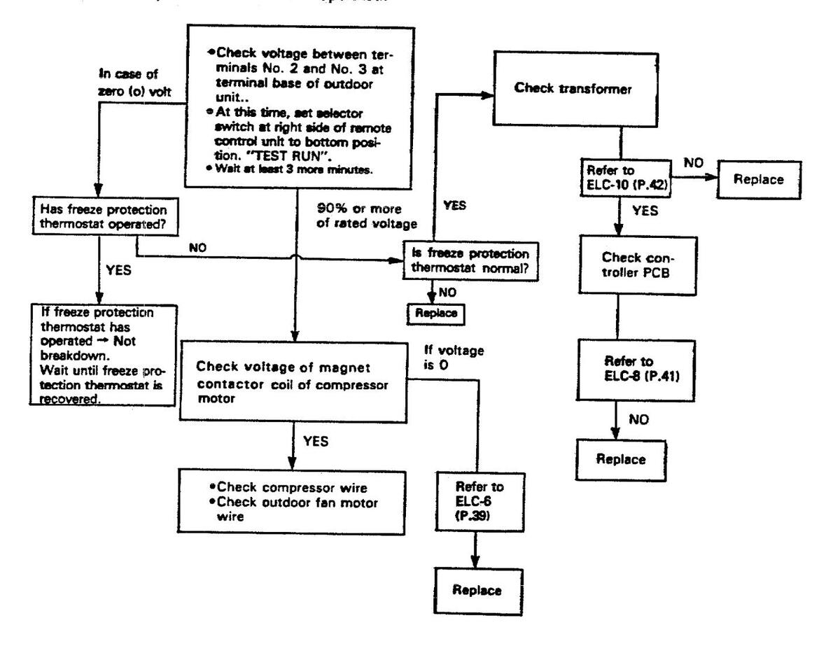
2.2 Neither outdoor fan nor compressor runs
Note: Check following points at first;
- 1. Is thermostat setting suitable?
- 2. Has 3 minute timer operated?
- (No operation for 3 minutes after power ON.)
3. Freeze protection thermostat operated?
2.3 Only outdoor fan does not run

NOTE: The fan motor does not run until the winding temperature lowers and automatic resetting works if the internal thermostat operates.
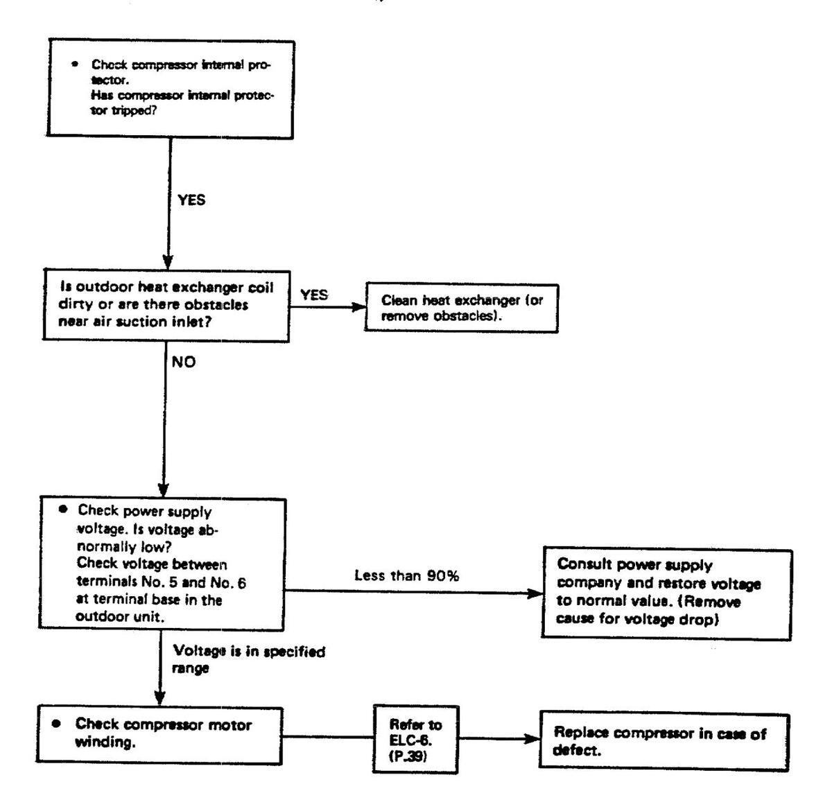
2.4 Only compressor does not run

2.5 Compressor frequently repeats ON and OFF
(Only compressor repeats ON and OFF, while indoor unit and outdoor fan run without fall.)
3. Air conditioner operates, but abnormalities are observed
3.1 Poor cooling

3.2 Excessive cooling

8 . CHECKING AND REPLACING ELECTRICAL COMPONENTS
| -Quick Access Index- | Page |
|---|---|
| ELA. Connector Identification on Controller PCB | |
| ELC-1 Measurement of Insulation Resistance of the Power Cord | |
| ELC-2 Measurement of Insulation Resistance of the Compressor | |
| ELC-3 Measurement of Insulation Resistance of the Fan Motor | |
| ELC-4 Checking of the Outdoor Fan Motor | |
| ELC-5 Checking of the Motor Capacitor | |
| ELC-6 Checking of the Compressor Motor Winding | |
| ELC-7 Checking of the Remote Control Unit Proper | |
| ELC-8 Checking of the Continuity of Fuse on the Controller PCB | |
| ELC-9 Method to Replace Fuse on the Controller PCB | |
| ELC-10 Checking of the Power Transformer | |
| ELC-11 Checking of the Indoor Fan Motor | |
| ELC-12 Checking of the Thermostat (Outdoor Unit) | |
| ELC-13 Checking of the Electric Magnetic Contactor | |
| ELC-14 Checking of the Crankcase Heater | |
| ELC-15 Checking of the Dewproof Warmer |
ELA. Connector Identification on Controller PCB
POW-24K (For SAP183KC)


- 1. Connector, Power Supply to PCB *
- 2. Connector, Transformer (Primary: * )
- 3. Connector, Fan Motor * 4. Connector, Transformer (Secondary: 19 V)
- 5. Connector, Remote Control Unit 24 V
- 6. Connector, Dewproof Warmer*
*Line voltage
ELC-1. Measurement of Insulation Resistance of the Power Cord
Clamp the ground (GND) line of the Power Cord with a lead clip of the insulation resistance tester and measure the resistance by placing a probe on either of the two power lines.
Then also measure the resistance between the GND line and the other power line. The insulation is in good condition if the resistance exceeds 1 MΩ. Fig. E-1.
ELC-2. Measurement of Insulation Resistance of the Compressor
Disconnect the black and white leads from the capacitor for the compressor motor, then measure the insulation resistance between one of these leads and the GND terminal. The insulation is in good condition if the resistance exceeds 1 MQ (Fig. E-2).
ELC-3. Measurement of Insulation Resistance of the Fan Motor
3.1. In case of indoor fan motor
Remove the fan motor connector from controller PCB (P36, Fig. E-A). Clamp the green lead wire (at the bear section) extended from the terminal GND in the electrical component box and measure insulation resistance by placing a probe of the insulation tester to either pole of this connector.
The insulation is in good condition if the resistance exceeds 1 MΩ. Fig. E-3.
Note:
If the probe does not enter the pole because the hole is too narrow then use a probe with a thinner pin.
3.2. In case of outdoor fan motor
Disconnect the GRY FM lead connected to the compressor capacitor. Clamp this lead wire with a lead clip of the insulation resistance tester and measure the resistance by placing a probe of the tester to the terminal GND. The insulation is in good condition if the resistance exceeds 1 MQ. Fig. E-4.
3.3. Crankcase heater
Disjoin and check both ends of the crankcese hester.


Fig. E-4
ELC-4. Checking of the Outdoor Fan Motor
CAUTION: Be sure to switch off the power.
- a) Disconnect the brown (BRN) and pink (PNK) lead wires from the fan motor capacitor.
- b) Remove the grey (GRY) lead wire from the compressor capacitor.
- c) Check the continuity for both ends of the PNK lead wires from the fan motor and the GRY lead wires from the compressor capacitor.
- d) Set the resistance measuring range of the multimeter to "X12" and measure the resistance between the fan motor isad wires. {Table-1}
SAP183C
| Lead wire color | Coil resistance | |
|---|---|---|
| WHT-BRN | 8 6 Ω±10% | |
| YEL-PNK | 6 0 Ω±10% | |
|
PNK-GRY
(PNK-BRN) |
22∪ ≌±10% | |
(Table-1)
Note: When ambient temp. is 70°F
ELC-5. Checking of the Motor Capacitor
Checking of any of the indoor fan motor capacitor, outdoor fan motor capacitor and compressor motor capacitor can be stone by the same method.
Remove both the lead wire terminals connected to the sepacitor, place the probe on the capacitor terminals as shown in the Fig. E-6 and observe the deflection of the pointer, setting the resistance measuring range of the multimeter to the maximum value.
For good condition of the capacitor, the pointer bounces to a great extent and then gradually returns to its original position.
The range of deflection and deflection time differ according to the capacity of the capacitor.
SAP183C ELECTRIC WIRING DIAGRAM

Fig.E-5

Fig. E-6
ELC-6. Checking of the Compressor Motor Winding
Remove the terminal cover of the compressor motor, set the resistance measuring range of the multimeter to "X1Ω" and check the continuity between each pair out of the 3 serminals as indicated in Fig. E-7.
It is in good working condition if there is continuity among each pair of terminals. (Table-2)
SAP183C
| Leadwire color | Coil resistance |
|---|---|
| C-R | 1.15 ♀ ±10% |
| C-S | 2.39 ♀ ±10% |
Note: When ambient temp is 77°F.
- ELC-7. Checking of the Remote Control Unit Proper
- A. Caution: Use of the Test Switch (TEST RUN)
The position of the switch which is used to operate the air conditioner for a room temperature below 65°F(18.3°C) is the position of the switch for this TEST RUN.
If this operation is continued for a long time, there would be a bad effect on the air conditioner because of overcooling. Therefore, use this switch only for checking, and in any case, DO NOT KEEP ON COOLING FOR MORE THAN 15 MIN. UNDER TEST RUN MODE.
When the checking is over, TURN THE SWITCH BACK TO ITS ORIGIN.______ SITION (= RUN) WITHOUT FAIL.
NOTE :
If the room temperature is too low, cooling operation may not be possible even if the thermostat knob is set at the lowest position.
- In this event, perform test run as follows:
- a) Pull off the thermostat knob. Fig. E-8.
- b) Set the thermostat lever to the lowest position. (The central position of the lever becomes the TEST RUN position.) Fig. E-9.
- c) Press OPERATION "ON" button to start the air conditioner.
- d) After completion of test run, press "OFF" button to stop the unit.
- e) Reinstall the thermostat knob. (The stopper position facing down.)
B. Checking of the Items of the Remote Control Unit
At first, pull out the connector (6P) of the remote control unit from the controller PCB of the unit (refer to Fig. E-10).
(1) Fan Speed Selector
Check the continuity of the connector No. 3 against No. 4 (place the negative (-) probe on No. 4 and positive (+) probe on No. 3. [Table-3]
| Checking points | Position of the selector | ||
|---|---|---|---|
| High | Low | ||
| 3-4 | NO | NES | |
(Table-3)
NOTE: YES ..... Continuity NO ..... Discontinuity
(2) Checking of the Operation Pushbutton The operating switch is in good working condition if there is continuity between No..2 (placing the negative (~) probe and No. 3 (placing positive (+) probe) while the pushbutton is pressed.
CAUTION:
Do not disassemble the Remote Control Unit.
It is supplied as a complete assembly and is carefully adjusted in the factory by skillful workmanship. Inexperienced disassembly will cause trouble and malfunction in the unit.
Fig. E-10
ELC-8. Checking of the Continuity of Fuse on the Controller PCB
Check the continuity by the multimeter as shown in Fig. E-11.
Measure the resistance value using a multimeter set to the "x1 ohms" range.
CAUTION: Disconnect the 4P power connector. (Refer to P. 36)

Fig. E-11
ELC-9. Method to Replace Fuse on the Controller PCB
- 1. Remove the controller PCB
- Pull out the fuse at the metal clasp by a pair of pliers while heating the soldered leads on the back side of the controller PCB with a soldering iron (30W or 60W). Fig. E-12.
- 3. Remove the fuse ends one by one. For replacement, insert a fuse of the same rating* and solder it.
Because the fuse is liable to melt, soder it quickly.
*Fuse: 250 V

Ele sure to replace the varistor adjacent to the fuse when the fuse is blown.

Fig. E-12
ELC-10. Checking of the Power Transformer
- 1. Remove connectors TRANS-1 and TRANS-2 from the controller PCB.
- 2. Set the resistance measuring range of multimeter to "X1Ω" and measure the resistance of the lead wires between WHT-WHT and BRN-BRN as shown in Fig. E-13.
It will be completely satisfactory if all measured values agree with those indicated in Table-4.
| Lead wires | Value of resistance | |
|---|---|---|
| WHT - WHT | About 143.50 | |
| BRN - BRN | 1.29 |
| OTE: Ambient room | temp |
|
70°F |
|---|
SAP183K ELECTRIC WIRING DIAGRAM

ELC-11. Checking of the Indoor Fan Motor
a
Remove the fan motor connector FM from controller PCB and measure the resistance between each lead wires of the fan motor connector setting the resistance measuring range to "X1Ω".
The motor is in very good working condition if all the values agree with those indicated in Table 5.
| Lead wires | Value of resistance |
|---|---|
| WHT-BRN | about 141 Ω |
| WHT-VLT | 83 Ω |
| VLT-PNK | 94 D |
| VLI-PNK | 94 D |
NOTE: Ambient room temp ....................................
ELC-12. Checking of the Thermostat (Outdoor Unit)
Disconnect the lead wire connected to the coil thermostat. Check the coil thermostat itself. Satisfactory if the value is as follows.
| the second s | |||
|---|---|---|---|
| and the second | |||
| i ocr | 900 | ||
| -7606 | 191 | ||
| 1 I | I DTE | ||
ELC-13. Checking of the Electric Magnetic Contactor
Disconnect (21) and (22) and check continuity using a multimeter. Satisfactory if continuity is assured. If continuity cannot be verified, the coil must be broken. Check and replace the coil.
ELC-14. Checking of the Crankcase Heater
Disjoin both ends and check continuity. Satisfactory if continuity is assured. If continuity cannot be verified, the heater must have broken wire. Check and replace broken wire.
ELC-15. Checking of the Dewproof Warmer
Disconnect Connector 2P for the dewproof warmer located by the power transformer and check continuity. Satisfactory if continuity is assured.
9. DISASSEMBLY AND SERVICE PROCEDURES
-Quick Access Index -
Page
| INDOOR UNIT SAP183K | |
|---|---|
| 9-1 Electrical Component Box — Removal | |
| 9-2 Evaporator (Indoor Heat Exchanger) and Drain pan - Removal | 46 |
| 9-3 Fan and Fan Motor — Removal | |
| OUTDOOR UNIT SAP183C | |
| 9-4 Cabinet — Removal | |
| 9-5 Fan and Fan Motor — Removal | |
| 9-6 Compressor Replacement | |
| 9-6-1 Tool List for Compressor Replacement | |
| 9-6-2 Safety Precautions | |
| 9-6-3 Compressor Replacement Procedures | |
| A. Separating the Outdoor Unit | |
| B. Removing the Old Compressor | |
| C. Installing a New Compressor | |
| 9-7 Leak Testing, Evacuation and Charging | 54 |
| 9-7-1 Required Tools and System Set Up | |
| 9-7-2 Leak Testing the System | |
| 9-7-3 Evacuation | |
| 9-7-4 Charging Refrigeant (R22) |
Indoor Unit SAP183K
- 9-1 Electrical Component Box-Removal
- Remove the side cover (A) by unfastening four black color screws.
- 2) Remove the front panel (B) by unfastening two black color screws.
- 3) Remove the cover plates (C) and (D) of the electrical component box in accordance with Figure D-1.

4) Disconnect the interunit wires from the terminal block.
5) Remove or loosen the connector socket and lead wires in accordance with Figure D-2.
CAUTION :
Do not apply an excessive force when removing the connector socket or lead wires.
6) Unfasten the screws in accordance with Figure D-2. The electrical component box can be pulled out.

g. D-2
-
9-2 E r Heat Exchanger) and Drain Pan-Removal
- 1) Remove the electrical component box.
- Remove the electrical component box. Remove the side cover (A) . Slide the sash (B) sideways to remove, then remove the air intake grille (with a filter) as shown in Figure D-3.
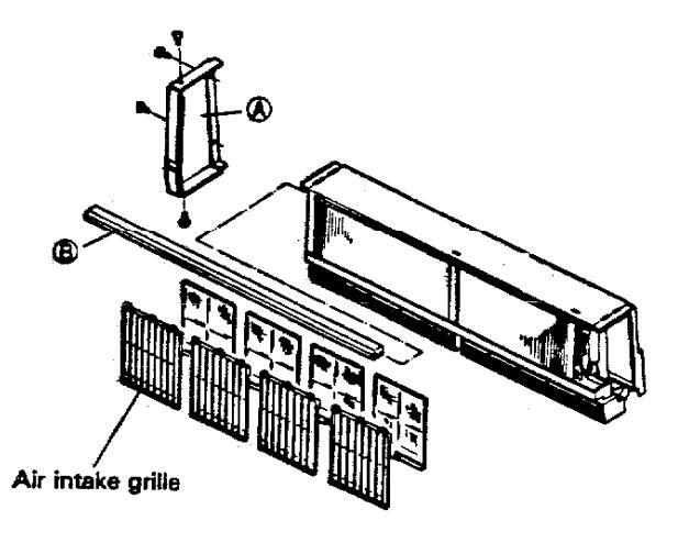
Fig. D-3
- 4) Remove the four mounting metals Ar.
- 5) Remove the refrigerant tubing holder B1. 6) The evaporator and drain pan can be pulled out after removing the screws shown in Figure D-4.

Fig. D-4
-
3 Fan and Fan Motor Removal Remove the blade mounting parts (A) (B) and (C) and pull the blade (D) out.
- 2) Remove the bottom plate (D. (See Figure D-5.)

Slide and pull out the mounting metal (G) from the bottom plate (E) to remove the dewproof warmer (F)

Fig. D-5
- 3) Remove the bearing case (A) and bearing assembly (B)
- 4) Loosen the fan fixing bolts (C) using a hexagor key.
- 5) Slide the fans left and right to remove them.
- 6) Remove the motor cover (D) and unscrew the screws (E) fixing the motor to open the motor fixing arm (F) as shown in Fig. D-6.
- 7) The fan motor can be removed in front as shown in Figure D-6.

Outdoor Unit SAP183C
94. Cabinet - Removal
Remove the cabinet by removing fixing screws using a Phillips screwdriver. Fig. D-7
Note: When working only on the wining, it is possible to gain access to the wining terminals by simply removing the Side Panel (A). Fig. D-8.

9-5. Fan and Fan Motor - Removal
- 1) Remove the fan by removing the propeller fan fixing son (A) using a straight blade screwdriver. Refer to Fig. D-9.
- 2) Using a pincher, cut the plastic wire ties fixing the fan motor lead wires connected to fan motor capacitor or other terminals.
- 3) Using a Phillips screwdriver, remove the three fixing screws of the fan motor, then withdraw the fan motor.

Fig. D-9
9-6. Compressor Replacement
9-6-1 Tool List for Compressor Replacement
| No. | ltem | Q'ty | Remarks |
|---|---|---|---|
| 1 | Portable fire extinguisher | 1 | |
| 2 | Oxy-acetylene torch set | 1 | Prest-O-Lite Portable Dutfit or equivalent |
| 3 | Torch lighter | 1 | |
| 4 | Oxweld goggles | 1 | |
| 5 | Brazing flux | 1 | |
| 6 | Soldering rod | 1 | |
| 7 | Vacuum pump (Capacity: 2 ~ 3 Cu-ft./min.) | 1 | Robinair or equivalent |
| 8 | Nitrogen gas (in 10 lb. container) | 1 | |
| 9 | Refrigerant R22 (in 10 lb. container) | 1 | |
| 10 | Refrigerant charging cylinder (5 lb. or more) | 1 | |
| 11 | System analyzer valve set | 1 |
Robinair, Imperial or equivalent
"Robbi" thermistor vacuum gauge or equivalent |
| 12 | Vacuum gauge (Range 0 – 1000 microns) | 1 | |
| 13 | Charging hose W/ 1/4" fittings | 5 | |
| 14 | Charge fitting 1/4" | 1 | |
| 15 | Tube adapter 1/4" | 1 | |
| 16 | Pinch-off tool | 1 | |
| 17 | Diagonal cutting pliers | 1 | |
| 18 | Long-nose side cutting pliers | 1 | |
| 19 | Slip-joint pliers | 1 | |
| 20 | Torque wrench (340 lb.) | 1 | 1 1 |
| 21 | Tube cutter | 1 | Imperial or Rigid |
| 22 | Flaring tool | 1 | Rigid or equivalent |
| 23 | Swaging tool | 1 | |
| 24 | Combination file set | 1 | |
| 25 | Regular screwdriver 8" | 1 | |
| 26 | Phillips screwdriver 6" | 1 | |
| 27 | Adjustable wrench 10" | 1 | |
| 28 | Adjustable wrench 12 " | 1 | |
| 29 | Hex. nut driver (6mm) | 1 | (For compressor bolt) |
| 30 | Oil pan | 1 | |
| 31 | Liquid soap with a brush | 1 | |
| 32 | Clean moist cloth | 1 |
9-6-2 Safety Precautions
- 1. Make sure unit is disconnected from the power source while it is being assembled or disassembled for servicing.
- Wear protective goggles at any time when brazing or unbrazing. Be sure to confirm system is at atmospheric pressure before using torch.
- 4. When brazing or unbrazingtubes, never locate face or any other parts of the human body in direct line with the tube opening.
- 5. Before commensing the trial run, be sure the unit is correctly wired and is grounded adequately when it is connected to the power.
8-5-3 Compressor Beplacement Procedures
A. Separating the Outdoor Unit
In case the compressor malfunctions with a split type air conditioner under normal conditions, release the refrigerant gas at the location first and remove the tubing, then separate the outdoor unit. Pay special attention to ventilation if the place of installation is small.
- 1) Make sure that the power is definitely turned OFF and remove the Access Panel "C" of the outdoor unit with power line and inter-unit line connectors. Remove wires from terminals within the electrical component box and wrap the ends of the wires separately with the insulating tape.
- 2) Place an oil pan at the under side of the service valves. Then remove the caps of the wide tube service valve and narrow tube service valve with an adjustable wrench.
- 3) Leave the wide tube service valve fully close by turning the spindle of the valve clockwise with a valve key or ratchet wrench. Close the narrow tube service valve in the same manner.
- 4) Apply two pairs of adjustable wrenches to the union of the wide tube service valve, then disconnect tubing from the butdoor unit.
- 5) Use an adjustable wrench and a torque wrench (130 ~ 170 lbs. in.), and disconnect narrow tube from the outdoor unit.
The refrigerant gas will seep out from the indoor unit as well as the tubing.
- 6) Seal the ends of the tubing so that no moisture or dust to enter.
- 7) Gradually open the narrow tube service valve and release the remaining refrigerant.
- 8) Open the wide tube service valve and release the remaining refrigerant.
- 9) Finally leave the wide tube service valve and narrow tube service valve fully open.
- 10) Clean the oil that has spread around the periphery.
- 11) Keep the separated outdoor unit in an upright position and carry it to the service station.
B. Removing the Old Compressor
-
1) 1. Disconnect the power supply
- 2. Remove parts from the unit as required to gain access to the compressor.
- 3. Place an oil pan under the process tube to be nicked.
- 4. Remove nut 5, cover and gasket.
- Remove nursh, cover and gastet. Remove all wiring from compressor terminals. Fig. D-10, 11. Remove all anchor nuts which are used to ascure the com-
- remove an anchor nots which are used to a pressor in the unit. Fig. D-10, 12. Purge gas from the capillary tube service veive.


Fig. D-11
Mounting Components

Fig. D-12
IMPORTANT NOTICE
Before installing the new compressor, check for possible system contamination by the following procedure:
- Place about 10 cc of the oil from the old compressor into a transparent container and visually check the degree of oil contamination. If the oil has a slight burnt odor but no color change or residue, and ordinary compressor replacement accoring to the instructions below may be carried out.
- If the oil has a burnt pungent odor and shows contamination (dark color with tiny particles of metal) the system must be cleaned sufficiently with a suction filter or a drier-strainer and then replace the oil drier with a new one.
- However, if just the compressor is replaced without sufficient system cleaning, contaminated oil may cause the buring of the compressor again,
- If the oil compressor is to be scrapped, by pinching the terminal section with a pair of pliers, there should not be any chance of it being mistakenly used.
-
2) 1) With an Oxγacetylene torch, unbraze the joint between the suction tube and the tip of the accumulator A) and pull free with pliers
- 2) Unbraze the joints on the compressor discharge tube (B), then pull free with pliers.
- 3) Unbraze the auxiliary tube (C) connected to the liquid injection tube. Fig. D-13.
CAUTION:
Plastic material in a check valve or a 4-way reversing valve is weak against direct heat.
When brazing or unbrazing across such parts, be sure to provide damp cloth over them and special care should be taken so as not to burn internal components.
3) 1) Take off the 2 screws (a) to remove the capillary tube from the compressor. Fig. D-14
-
4) 1) Cut the portion (a) of the auxiliary tube connected to the capillary tube with a tube cutter. The auxiliary tube will be reused so should not be thrown away. Fig. D-15
- 2) To remove the compressor raise it straight and disengage from the base unit.
- Remove the cushion nubbers from the old compressor (3 sets) and save them.

C. Installing a New Compressor
-
1) 1. Nick the end of the pinched suction tube of the new compressor with a pincher and release the holding charge (Nitrogen: 29 PSIG)
- 2. With an oxyacetylene torch and pliers, unbraze the compressor neets (A), (B) and (C) Fig. D-16

Fig. D-16
Holding it with pliers, braze the previouly removed auxiliary tube onto the liquid injection tube of the new compressor. Fig. D-17

Fig. D-17
Accumulator
3) 1. Transfer cushion rubbers to the new compressor.
- 2. Install the new compressor in exactly the same manner as the original compressor.
- Bend both the suction and discharge lines to bring the ends to the area of the compressor fittings and engage each tube end into the matching compressor fitting.
- 4. Hold tubing securely with pliers and braze connections (A) (B) and (C) carefully with torch Fig. D-20
- 4) When the tube has cooled, apply soapy water to the brazed joint to check for refrigerant leaks.
- 5) Connect compression terminal wiring.
- 6) Tighten the compressor anchor nuts (3 pcs) to the rated torque.
- 7) Turn on the power supply and start up the air conditioner.
Fig. D-18
9-7. Leak Testing, Evacuation and Charging
9-7-1. Required Tools and System Set UP
| No. | Q'ty | |
|---|---|---|
| 1) | Vacuum pump | 1 |
| 2) | Vacuum gauge | 1 |
| 3) | System analyzer valve set | 1 |
| 4) | Charging hose (With 1/4" connector) | 6 |
| 5) | 1/4" Flared tube cross fitting | 1 1 |
| 6) | Charging Cylinder | 1 |
| 7) | 1/4" Flared Packless valve | 3 |
| (To be used for V3, V4 and V5) |
- One of conventional system set up and procedure for leak testing, evacuation and charging is described in section 9-7 for the reference.
- ** Robinair or Imperial Portable Charging Station may be used as a convenient packaged tool for the purpose of servising the refrigerant system.
Gasket Charge fitting
Fig. D-19

Fig. D-20
9-7-2. Leak Testing the System
After replacement of the new compressor, the system must be checked for leaks according to the below mentioned procedure:
- *1 If cylinder has not yet been filled, move at least one pound of refrigerant (R22) to the charging cylinder. Fig. D-19
- 1) Prepare the system analyzer valve set and connect charging hoses as in Fig. D-20. Be sure to close all valves before connection.
- 2) Confirm that both Narrow Tube and Wide Tube service valves on the outdoor unit VID and VID are opened halfway, and other valves are still closed.
- 3) Open valves (VB), V4) and V2 respectively to allow refrigerant gas entering into the system. Fill gas to the system and close (V2), V4 and VB in sequence.
4) Apply liquid soap at:
- Charge hose connectors.
- Discharge and auction tubes.
- Brazed liquid injection capillary section of the replaced compressor or other connection parts.
- Check to see change of bubbles. An electronic halogen gas leak detector, of course, may be used for this purpose.
9-7-3. Evacuation
- 1) Connect instrument as in Fig. D-21
- 2) confirm that all connections are made correctly and check all valves are closed. * V6 and V7 should be opened
3) Open VP2 only.
- 4) Open WB and WB. Never fail to open the shut off value on the vacuum pump if there is.
- 5) Run the vacuum pump for evacuation. Required time for complete evacuation differs with capacity of the pump (Consult shop manual for specifications.)
* While system is evacuating, utilize this time to fill the charging cylinder, if it is not ready.
- 6) If vacuum gauge reading has reached 500 microns or less. stop the vacuum pump and close V3.
- 7) Keep this condition at least 5 minutes and observe the vacuum gauge for change. (Fig. D-22) If pointer on the gauge moves to larger numbers, check system for leaks again according to the procedure in section 9-7-2. Page 54.
- 8) If the indication of the vacuum gauge will not char system is now prepared for charging refrigerant. Close (VID .
- 9) Proceed to charging rufrigerant in section 9-7-4, Page 56.

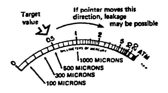
Fig. D-22
$-7-4 Charging Refrigerant (R22)
- · Preparation of Refrigerant
- a) Measure the net weight of the charging cylinder before charging refrigerant and memorize it,
- b) Refill required amount of refrigerant from the container to the charging cylinder. Be sure to measure the cylinder contents by weighing it. Fig. D-23

- Charging Procedure
- 1) Evacuate system according to the procedure in section 9-7-3
- 2) Confirm that valves VI2, V2, V3, V4, V5, and V3 are closed when evacuation is completed.
- 3) Open charging cylinder valve VB slightly.
- 4) Loosen hose connection at W4 a little to let air escape from the hose. Then tighten connection again.
- Measure and memories charging cylinder weight to charge exact amount of refrigerant.
- 6) Open (VA) fully to supply refrigerant gas to (V2)
- 7) For charging refrigerant, check that VI is set in a halfway position.
- 8) Open V2 gradually and let refrigerant gas entering into the system.
- When full charge has entered system. Close V2 tightiv.
CAUTION: Do not permit liquid lever to drop below "0" (zero) on the graduation of the charging cylinder.
- 10) Open W7 fully until they are turned all the way.
- 11)Ciose VA and V8
- 12)Loosen hose connections and let refrigerant escape from hoses.
- 13)Remove hoses, charging cylinder and system analyzer valve set. Now, system charging has completed.

SAP183K INDOOR UNIT

SAP183K INDOOR UNIT
ATTENTION !
To ensure correct parts supply, please let us know followings, when you make service parts order: 1. Part No. 2. Description 3. Q'ty 4. Volts-Hz-Ph 5. Product Model NO.
|
Ney
No. |
Part No. | Description | 0'++ |
|---|---|---|---|
| 1 | 854-0-1109-197H1 | Rear Panel Ass'y | |
| 2 | 854-2-2360-37801 | Nounting Plate | + + |
| 3 | 854-2-1129-41401 | Mounting Plate | 1 3 |
| 4 | 854-0-2502-19200 | Fan Casing Ass'y | 1 1 |
| 5 | 854-2-2316-10201 | Nounting Plate | 2 |
| 854-0-2511-17101 | Support Motor Ass'y | Ī | |
| 854-0-2323-27901 | Nounting Plate Ass'y | 1 | |
| 851-0-5290-637N1 | Fan Motor Ass'y KFH4T-21B6SP | 1 | |
| - Å | 852-2-2511-12110 | Cushion Rubber | 2 |
| 10 | 854-0-2501-16200 | Centrifugal Fan Ass'y | 1 |
| 854-0-2501-16300 | Centrifugal Fan Ass'y | 1 | |
| 12 | 854-0-2512-12301 | nounting Ass'y, Bearing | 1 |
| 13 | 854-0-2512-12400 | Nounting Ass'y, Bearing | 1 |
| 852-0-2510-12200 | Bearing Housing Ass'y | 2 | |
| 1 12 | 004-2-2000-02110 | Packing Disks | 2 |
| + + - + | 004-2-1129-39301 | nounting Plate | |
| 004-2-1129-44501 | nounting Plate | 1 | |
| + + 8 | 534-U-4118-34601 | Evaporator Ass'y | 1 |
| 172 | 834-2-2313-162H1 | Hand Ass y | 1 1 |
| 20 | 854-0-5301-33101 | Elec. Component Box Ass'y | 1 |
| ┝╶╧┇┥ | 859-4/2-91 | Controller Ass'y PDN-24K | |
| 22 | 851-2-5366-01400 | Spacer LCBS-6N | 4 |
| 23 | 854-0-5301-347H2 | Elec. Component Box Ass'y | ┥──┦ |
| 64 | lerminal Base J1020-3 | ||
| 20 | 852-0-4/29-1/300 | Ladei | 1 1 |
| Screw Specal (EARIH) | | | ||
| 21 | 031-0-5290-037P1 | Transformer Ass y Alk-J1220 | |
| 20 | 4-2239-50218 | Fixed Capacitor 440V 2NFD | |
| 29 | 851-0-0051-1/100 | Remote Control Unit Ass y RCS-183K | ↓ |
| 30 | 851-0-5292-13300 | Kenote Control Cable | |
| 31 | 851-2-5365-03302 | Indicator Plate | 1 1 |
| 32 | 851-2-5359-00520 | Lid, Remote Control Unit | |
| 33 | 851-2-5358-00620 | Bottom Plate | 1 |
| 34 | 800-2-5328-12602 | Switch Knob | 2 |
| 35 | 854-2-1311-12002 | Knob | |
| 36 | 851-0-5158-24100 | Control Switch PCB Ass'y RCS-183K | |
| 37 | 800-2-5367-11300 | Filter | 1 |
| 38 | 851-2-5380-02300 | Filter | |
| 39 | 800-2-5352-14801 | Nounting Plate | |
| 40 | 854-2-1311-12401 | Knob | |
| 41 | 4-2339-56224 | Thermostat RTB-4U301 | |
| 42 | 854-0-2301-340H1 | Drain Pan Ass'y | |
| 43 | UTAIN PIDE ASS'Y | ┝──┤ | |
| 44 | 834-2-2345-58201 | nounting Plate | |
| 45 | 854-2-1111-18812 | Support Louver | |
| 40 | Guide 3 | ||
| 4/ | nounting Plate | ⊢ ] | |
| 48 | Urnamental Sash Ass'y | ||
| 49 | 004-2-0012-400U1 |
nvunting flate
Nastar Acc'u 320V 138 |
├ ────‡ |
| 0011 | 091-0-9730-09(81) | HEALES ADD Y LOUT LOU |
NOTE: Metal and plastic parts will be supplied basically with necessary heat insulation pads or packing.
SAP183K INDOOR UNIT
ATTENTION 1
To ensure correct parts supply, please let us know followings, when you make service parts order:
1. Part No. 2. Description 3. Q'ty 4. Volts-Hz-Ph 5. Product Model NO.
| NS. | Part No. | Description | 0.14 |
|---|---|---|---|
| 51 | 854-2-1111-186H1 | Support Louver Ass'y | |
| 52 | 854-2-1129-41200 | Hounting Plate | |
| 53 | 854-2-1111-187H2 | Support Louver Ass'y | |
| 54 | 854-2-1110-138H3 | Blade Louver Ass'y | 2 |
| 55 | 854-2-1111-18912 | Support Louver | 1 1 |
| 56 | 854-2-1342-10901 | Spring Leaf | 2 |
| 57 | 854-2-1301-19910 | Ornamental Sash | 1 |
| 58 | 854-2-1104-12711 | Suction Grille | 4 |
| 59 | 854-2-1101-473H1 | Front Panel Ass'y | 1 |
| 60 | 854-2-1358-45700 | Label | ī |
| 61 | 854-2-5304-263H2 | Cover Plate Ass'y | 1 1 |
| 62 | 854-6-4729-71600 | Label | 1 |
| 63 | 854-2-1358-46700 | Label | Ī |
| 64 | 854-2-5304-262113 | Cover Plate Ass'y | 1 |
| 65 | 851-2-5250-76901 | Elec. Wiring Diagram | 1 |
| 66 | 854-2-1102-256H2 | Side Panel Ass'y | 1 |
| 67 | 854-2-1102-25511 | Side Panel | 1 |
| 68 | 854-2-1129-41501 | Nounting Plate | 2 |
| 69 | 854-0-1302-139H1 | Air Filter Ass'y | 4 |
| 70 | 854-2-1130-12901 | Nounting Plate | 1 |
| 71 | 854-2-4134-31301 | Mounting Plate, Evaporator | 1 |
| 72 | 852-2-1335-67000 | Name Plate | 1 |
| • | 852-6-4119-53700 | Operation Manual | 1 |
| 852-6-4139-67800 | Installation Instructions | 1 | |
| ٠ | 852-6-4139-51400 | Full-scale installation Diagram | 1 |
NDTE: Hetal and plastic parts will be supplied basically with necessary heat insulation pads or packing.
Accessory Parts LIST OF PACKAGED PARTS
SAP183K
| Description | Shape | any | Parts No. | Description | Shape | Qʻiy | Parts No. | |
|---|---|---|---|---|---|---|---|---|
| inaul. nipple | 1 | 854 2 2410 37610 |
Tapping
screw |
Trus HD
Phillips |
8 | 3 9219 42501 | ||
| Drein pipe | 1 | 854 2 2334 13800 | 4 x 25 mm (1") | |||||
| epeptor | Mounting | a | ||||||
| Full active installation | 1 | 852 6 4139 51400 | bracket |
For
remote |
900 2 5352 14901 | |||
| diagram | control | Trum HD | ||||||
| Wall fixture | 8 | 854 2 1130 12901 | screw | unit | Phillips | 2 | 3 9261 21301 | |

ATTENTION 1
To ensure correct parts supply, please slet us know followings, when you make service parts order:
1. Part No. 2. Description 3. Q'ty 4. Volts-Hz-Ph 5. Product Model NO.
| Kev | |||
|---|---|---|---|
| NO: | Part No. | Description | 0'tv |
| 1 | 852-0-2202-25201 | Bottom Plate Ass'y | |
| 2 | 852-0-4501-23900 | Valve Ass'v 1/4 in | + + |
| 3 | 852-0-4501-24000 | Valve Ass'y 5/8 in | |
| 4 | 851-2-2390-14000 | Cushion Bubber | |
| 5 | 851-2-2330-13201 | Spring | |
| - Â | 852-0-4511-12901 | Accumulater Acc's | 8 |
| 7 | 852-2-2353-15110 | Decking | |
| 852-2-2256-10001 | Packing | ||
| 852-2-4210 40000 | Banu Hounting | 1 | |
| 1 | 852-2-4219-49000 | Capiliary jube | 1 |
|
852-2-2309-34101
852-2-2253 10500 |
nounting Plate | 1 | |
| 832-2-2353-19500 | Packing | 2 | |
| 12 | Clamper F-5 | 1 | |
| 10 | 001-2-2000-10000 | Cushion Rubber | 3 |
| 851-0-5290-91581 | Heater Ass'y 230V 30V | 1 | |
| + | 002-2-2397-12100 | Nasner Special | 3 |
| 10 | 3-92/0-08001 | NUT Bas | 3 |
| 852-0-4102-31600 | Condenser Ass'y | 1 | |
| 18 | 852-2-2351-144H1 | Cover Plate | 1 |
| 19 | 852-0-4505-14700 | Dehydrater Ass'y | 1 |
| 20 | 852-2-4219-61700 | Capillary Tube | 1 |
| 21 | 852-0-4507-33100 | Nipple Ass'y | 1 |
| 22 | 852-2-2309-19909 | Nounting Plate | 1 1 |
| 23 | 852-2-2354-14284 | Nounting Plate Ass'y, Fan Notor | 1 |
| 24 | 851-0-5290-915M1 | Fan Motor Ass'y SC6S-51C6P | 1 |
| 25 | 852-0-5301-29201 | Elec. Component Box Ass'v | 1 |
| 26 | 4-2239-56218 | Fixed Capacitor 440V 2MFD | 1 |
| 27 | 4-2379-56170 | Terminal Base JT1120-6 | |
| 28 | 4-2239-56338 | Fixed Capacitor 400V 30NED | ┼──┼┤ |
| 29 | 852-2-5301-21201 | Clip Capacitor | ╡╶╶╡ |
| 30 | 1-2320-56281 | Palay CIV-1653-21 | ┼──┼ |
| 21 | 2-0214-40802 | CORDER CORCION (FADTU) | ┼──╬╢ |
| 201 | 0-5214-40802 | Sciew Special UP-0200 (EARIN) | ╉╍╍╼╬┨ |
| 02 | 001 2 6104 10100 | ┼──┊┤ | |
| 33 | 001-2-0194-12100 |
Uover, jerminal
Nub deseist (INAU) |
┥───┊┤ |
| 34 | 819-2-0919-10100 | NUT SPECIAL LINUHJ | ╀──┋┨ |
| 35 | 852-2-4514-30110 | Insulation lube | ↓↓ |
| 36 | 852-0-2209-103H2 | Partition Plate Ass'y | |
| 37 | 852-2-5303-14110 | nounting, ihermostat | |
| 38 | 851-0-5290-915T1 | Inermostat Ass'y NOT55 | |
| 39 | 852-2-2514-11300 | Cover Rubber | |
| 40 | 852-0-2502-12011 | Propeller Fan Ass'y | 1 |
| 41 | 852-2-2510-10201 | Bolt Special S45C N6+10 | 1 |
| 42 | 852-2-2353-36020 | Packing | 4 |
| 43 | 852-2-1112-15311 | Cabinet | 1 |
| 44 | 852-2-1316-19901 | Mark | 1 |
| 45 | 852-0-1111-13001 | Cuard Ass'y | 1 |
| 46 | 852-2-1316-21201 | Mark | 1 |
| 47 | 852-0-1111-12701 | Guard Ass'y | Ī |
| 48 | 852-2-1120-16011 | Rear Panel | i |
| 49 | 852-0-1104-155H1 | Side Panel Ass'y | ī |
| 50 | 851-2-5251-06001 | Elec. Wiring Diagram | 1 |
NOTE: Netal and plastic parts will be supplied basically
with necessary heat insulation pads or packing.
ATTENTION 1
To ensure correct parts supply, please let us know followings, when you make service parts order: 1. Part No. 2. Description 3. Q'ty 4. Volts-Hz-Ph 5. Product Model NO.
| Key. | Part No. | Description | Q'ty |
|---|---|---|---|
| 51 | 852-0-1104-156H1 | Side Panel Ass'y | 1 |
| 52 | 851-2-5370-01400 | Bushing | 3 |
| 53 | 852-2-2353-51000 | Packing | 1 |
| 54 | 852-0-1104-14311 | Side Panel Ass'y, Left | 1 |
| 55 | 852-2-1335-67100 | Name Plate | 1 |
| 56 | 854-6-4729-71600 | Label | 1 |
| 57 | 852-6-4729-17300 | Label | 1 |
| 58 | 854-2-1358-46700 | Label | 1 |
| 59 | 852-0-4516-16500 | Compressor Ass'y C-2R130H6U | 1 |
NOTE: Netal and plastic parts will be supplied basically
with necessary heat insulation pads or packing.
11. REFRIGEANT FLOW DIAGRAM
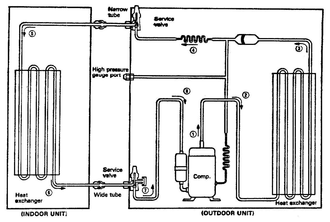
NOTE:
→ with sequential number shows flow of refrigerant in COOLING CYCLE.
12. ELECTRIC WIRING DIAGRAM


CONTROLLER P.C.B. (PRINTED PATTERN) POW-24K (For SAP183K)

CORPORATION SFS CORPORATION: 210 RISER ROAD LITTLE FERRY, NEW JERSEY 07643 1987/Nov./1000/TA Printed in Japan
For parts or service contact


 Loading...